Batterie haute tension (traction intégrale) (triphasé) (retrait et installation)
 Code de correction
16010221 REMARQUE : À moins d’indications explicites contraires dans la procédure, le code de correction et le temps forfaitaire ci-dessus représentent tout le travail à être fait pour cette procédure, notamment les procédures connexes. N’appliquez pas plusieurs codes de correction à la fois, à moins qu’il vous soit explicitement indiqué de le faire.REMARQUE : Consultez Temps forfaitaires pour en apprendre plus à propos des temps forfaitaires et de leur création. Vous pouvez transmettre par courriel vos commentaires relatifs aux valeurs des temps forfaitaires au LaborTimeFeedback@tesla.com. REMARQUE : Consultez Protection individuelle pour vous assurer de porter l’équipement de protection individuelle adéquat lors vous effectuez la procédure ci-dessous.
Code de correction
16010221 REMARQUE : À moins d’indications explicites contraires dans la procédure, le code de correction et le temps forfaitaire ci-dessus représentent tout le travail à être fait pour cette procédure, notamment les procédures connexes. N’appliquez pas plusieurs codes de correction à la fois, à moins qu’il vous soit explicitement indiqué de le faire.REMARQUE : Consultez Temps forfaitaires pour en apprendre plus à propos des temps forfaitaires et de leur création. Vous pouvez transmettre par courriel vos commentaires relatifs aux valeurs des temps forfaitaires au LaborTimeFeedback@tesla.com. REMARQUE : Consultez Protection individuelle pour vous assurer de porter l’équipement de protection individuelle adéquat lors vous effectuez la procédure ci-dessous.
- 2024-06-13: Updated lift pad adapter PNs.
- 2023-11-21: Added new lift pad instructions.
- 2023-08-23: Updated EPB Service Mode reference.
- 2023-07-11: Reorganized steps to accommodate service while standing.
- 2023-07-06: Added step to perform a charge port voltage check.
- 2023-05-05: Added step to position battery table under vehicle.
Retirer
-
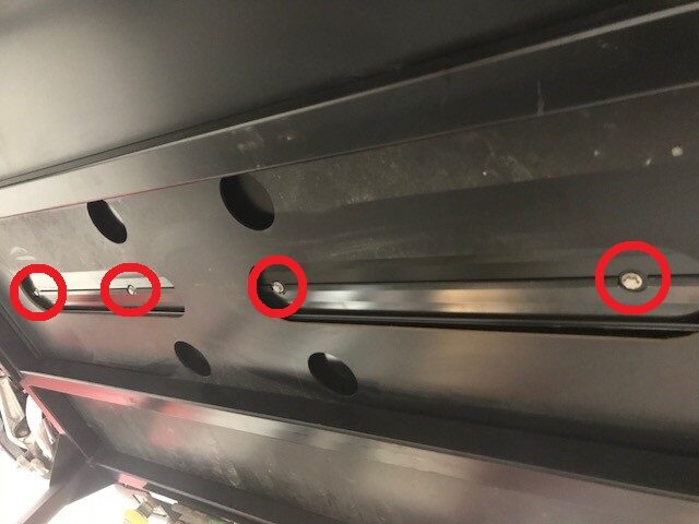
Remove bolts securing LH rocker panel
lower cover to body.
Remarque4x bolts, 10mm, 5 Nm, Release 4x covers to access bolts, The number of fasteners on newer vehicles may vary.
-
Remove clips securing the LH rocker
panel lower cover to wheel liners.
Remarque4x push clips.
-
Remove LH rocker panel lower
cover.
Remarque10x clips.
-
Remove bolts securing RH rocker panel
lower cover to body.
Remarque4x bolts, 10mm, 5 Nm, Release 4x covers to access bolts, The number of fasteners on newer vehicles may vary.

-
Remove clips securing the RH rocker
panel lower cover to wheel liners.
Remarque4x push clips.
-
Remove RH rocker panel lower
cover.
Remarque10x clips.
-
Open all four doors.
RemarqueIf vehicle is being powered down, Latch rear doors to prevent accidental closure.
- Lower all four windows.
-
Open hood.
RemarquePress "Open" button on the touchscreen to release the latch, Lift the lid manually.
-
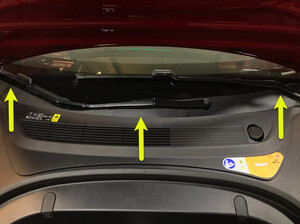
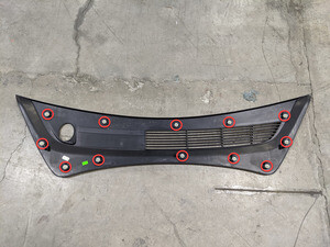
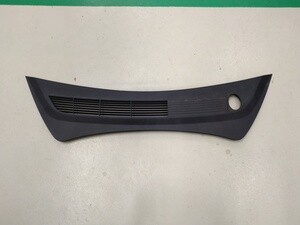
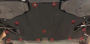
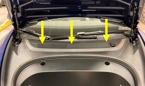
Remove rear apron.
Remarque12x clips, Only store rear apron visible face upwards .
-
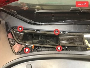
Remove cabin intake upper duct
assembly.
Remarque4x clips, Heat pump vehicles have 3x clips.

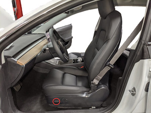
- Move LH front seat backward.
-
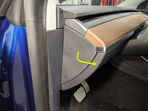
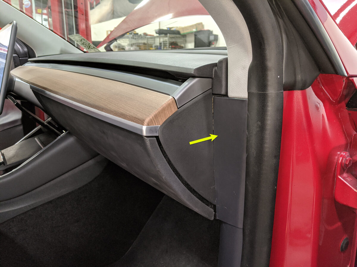
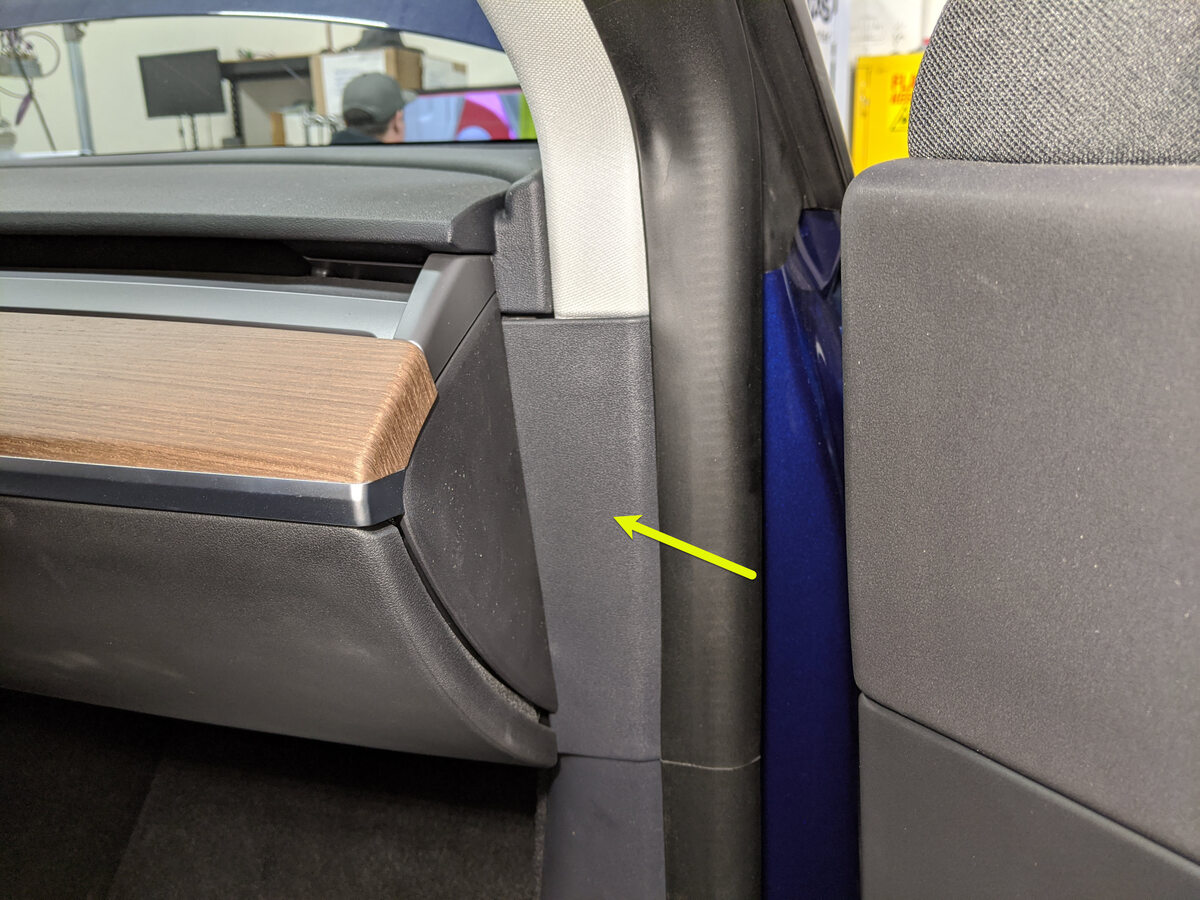
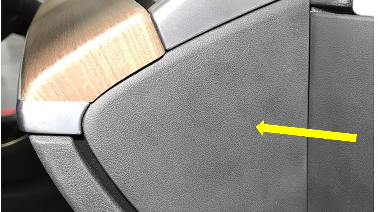
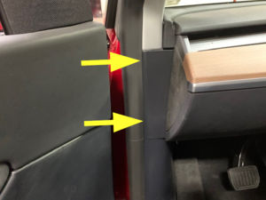
Remove LH IP end cap.
Remarque3x clips.
-
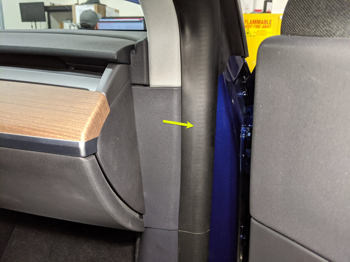
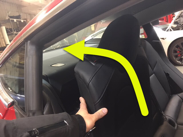
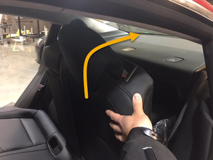
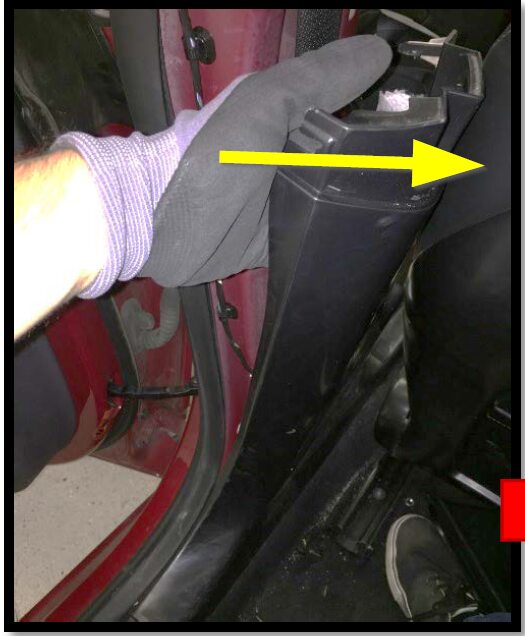
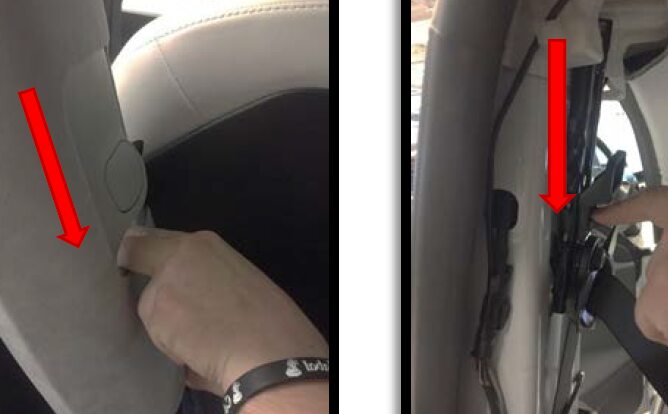
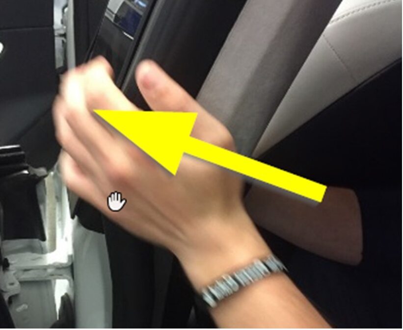
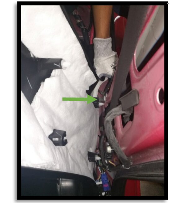
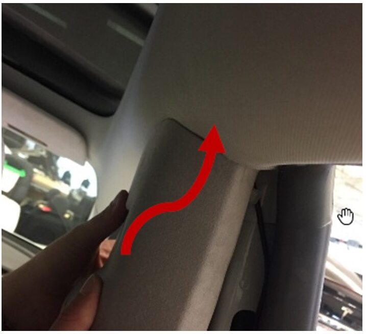
Remove LH mid A-pillar assembly.
Remarque1x clip, 1x tab, Release the upper clip then pull mid A-pillar upward to remove.

-
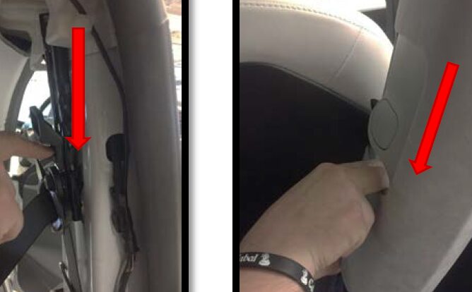
Remove clip for LH lower A-pillar
trim.
Remarque1x push clip.
-
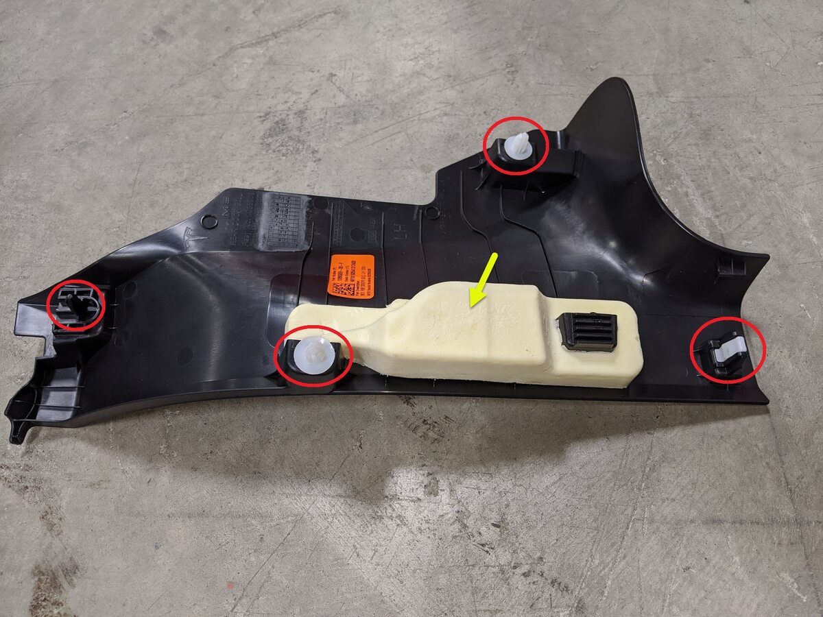
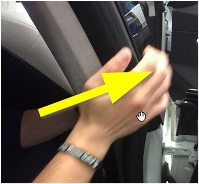
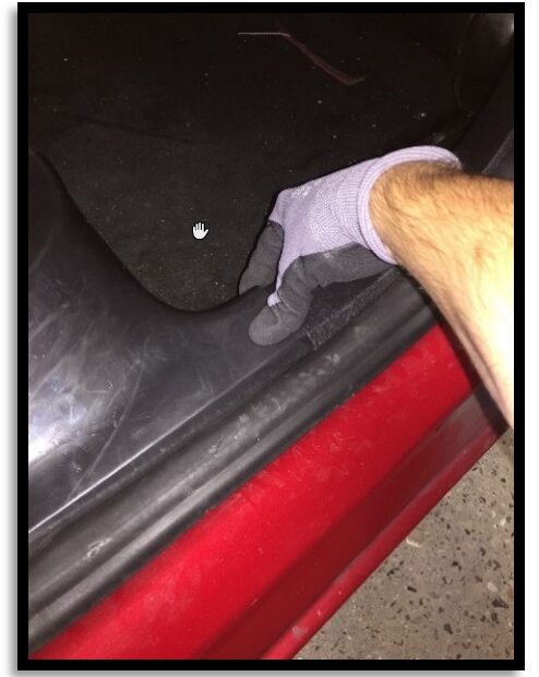
Remove LH lower A-pillar trim.
Remarque2x clips, 3 guide tabs, Pull rear of lower A-pillar upward to release clip then pull rearward to release front tabs from carpet.
-
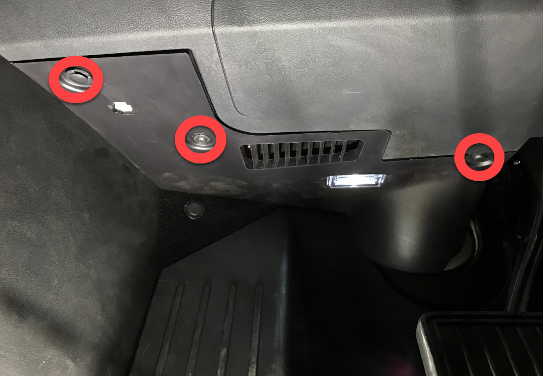
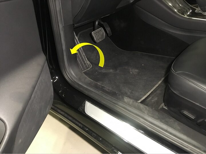
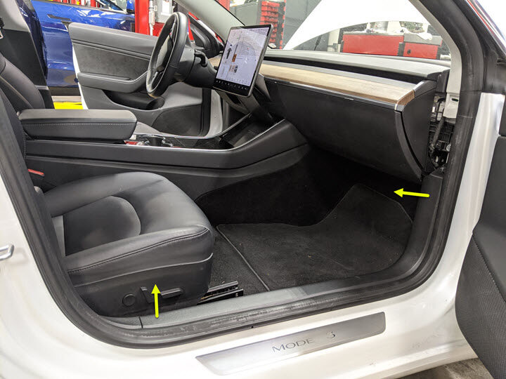
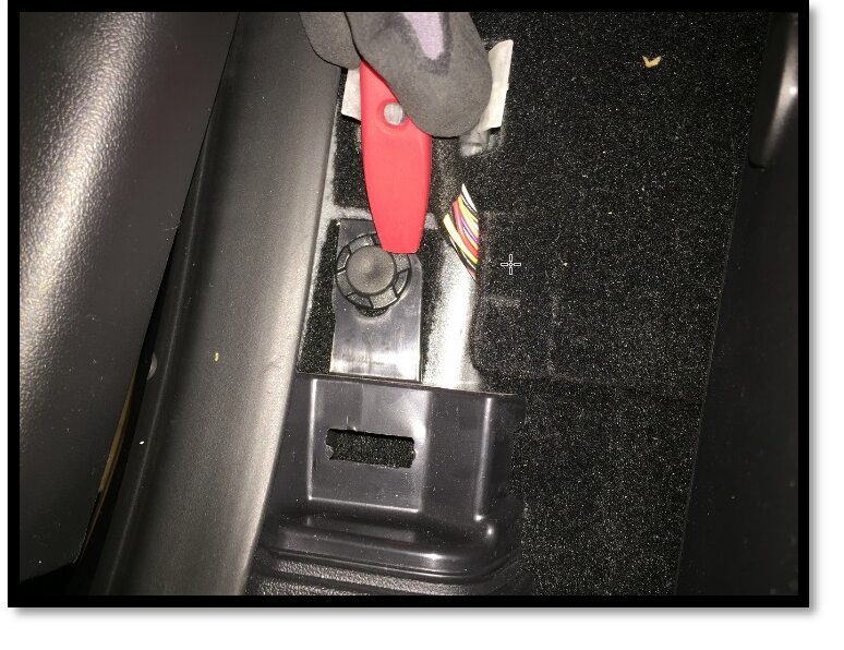
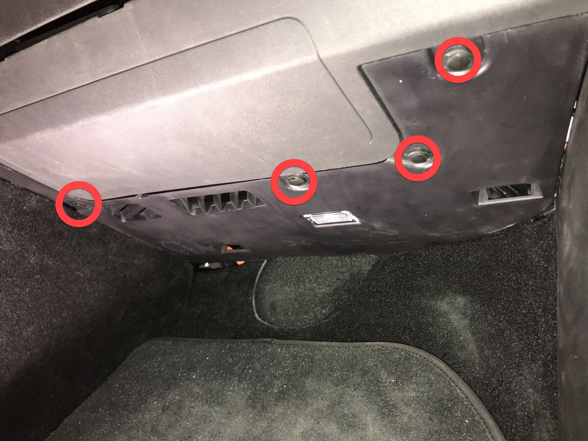
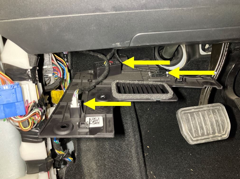
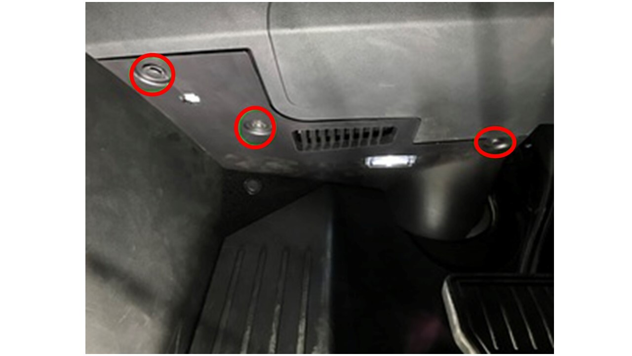
Remove screw and clips securing LH
footwell cover.
Remarque2x push clips, 1x screw, T20, 2.5 Nm.
-
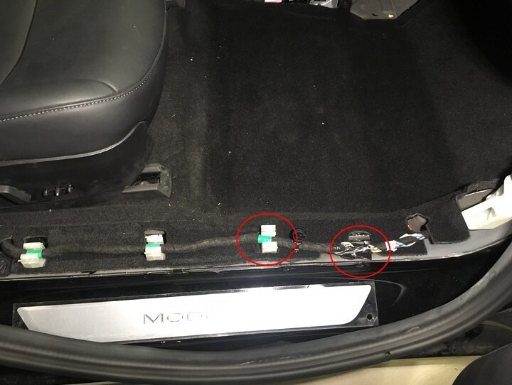
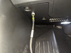
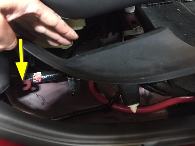
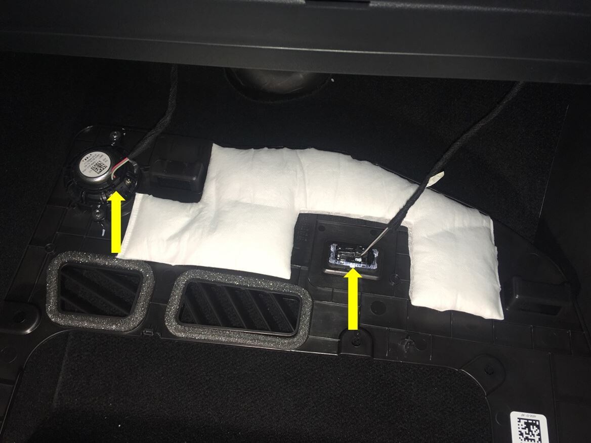
Remove connectors from LH footwell
cover and remove from vehicle.
Remarque3x tabs, 1x Ethernet connector, 1x puddle light connector, APAC specific vehicles have an additional OBDII connector that will have to be disconnected.

-
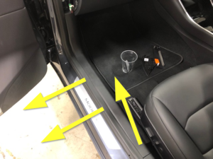
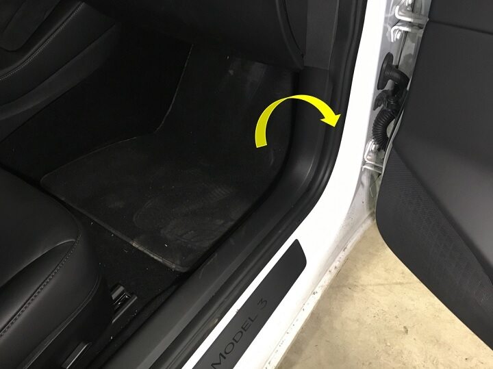
Remove LH front floor mat.
-
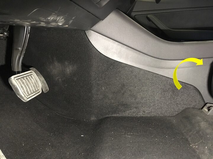
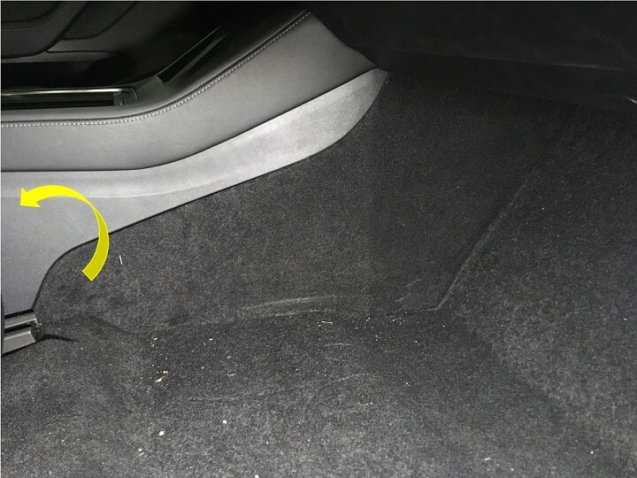
Remove LH console side panel
carpet.
Remarque12x clips, Use trim tool starting at rear edge to release upper clips, then pull bottom to release remaining clips.
- Move RH front seat backward.
-
Remove RH IP end cap.
Remarque3x clips.
-
Remove RH mid A-pillar assembly.
Remarque1x clip, 1x tab, Release upper clip then pull mid A-pillar upward to remove from vehicle.
-
Remove clip for RH lower A-pillar
trim.
Remarque1x push clip.

-
Remove RH lower A-pillar trim.
Remarque1x clip, 2 guide tabs, Pull rear of lower A-pillar upward to release clip then pull rearward to release front tabs from carpet.
-
Remove clips securing RH footwell
assembly.
Remarque4x push clips.

-
Disconnect RH foot well assembly
connectors and remove from vehicle.
Remarque2x electrical connectors.

-
Remove RH front floor mat.
-
Remove RH console side panel
carpet.
Remarque12x clips, Use trim tool starting at rear edge to release upper clips, Pull bottom to release remaining clips.
- Move RH front seat forward.
- Move LH front seat forward.
- Remove 2nd row floor mat from vehicle.
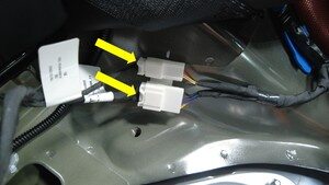
-
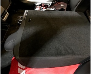
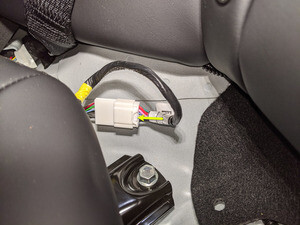
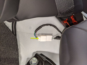
Remove 2nd row seat cushion and
disconnect harness.
Remarque2x tabs, 2x connectors, Press tab toward vertical backward of vehicle on each side to release front edge of seat cushion.

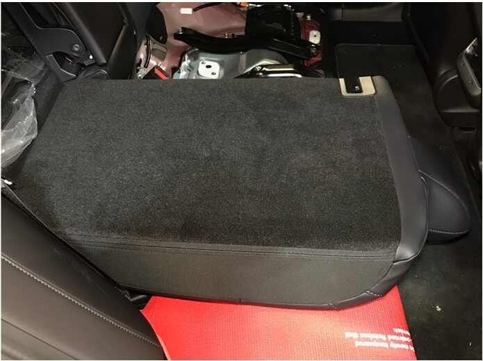
-
Fold the 40 seat in down
position.
RemarqueProtect the seat cushion.
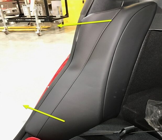
-
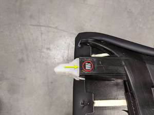
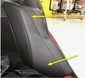
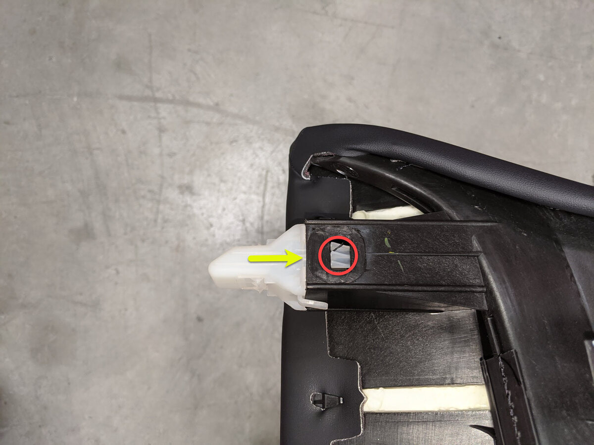
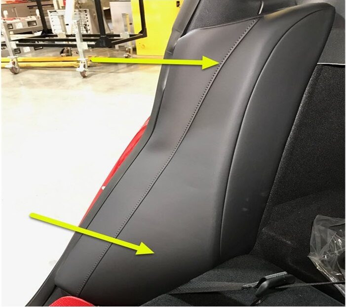
Remove RH side bolster.
Remarque1x clip, 1 tab, Pull outward then slightly upward to remove.
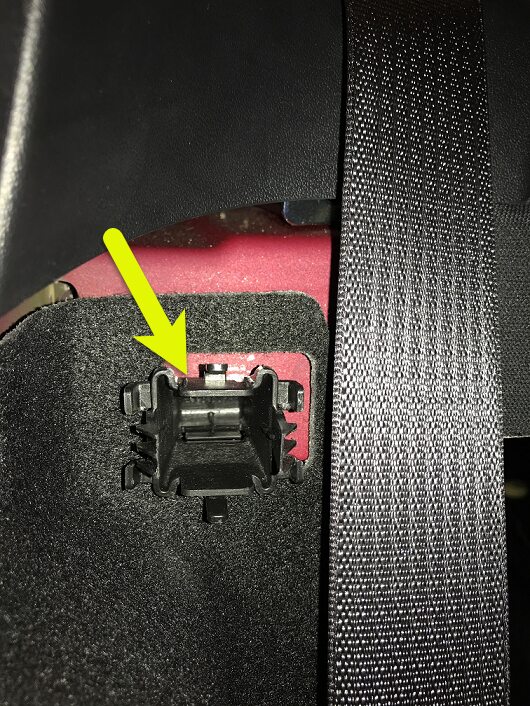
-
Remove and discard bolster plastic
bracket from RH side.
Remarque2x clips, If necessary, depress the clips from behind, this bracket may come out with bolster. Discard after removal.
-
Fold the 40 seat into vertical
position.
-
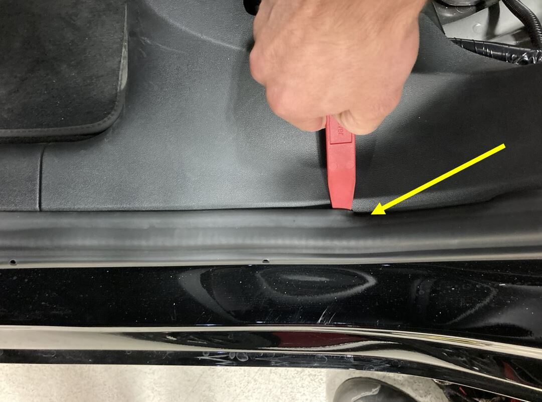
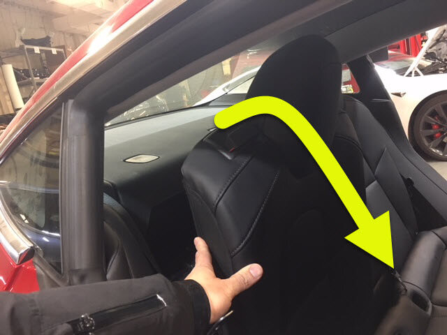
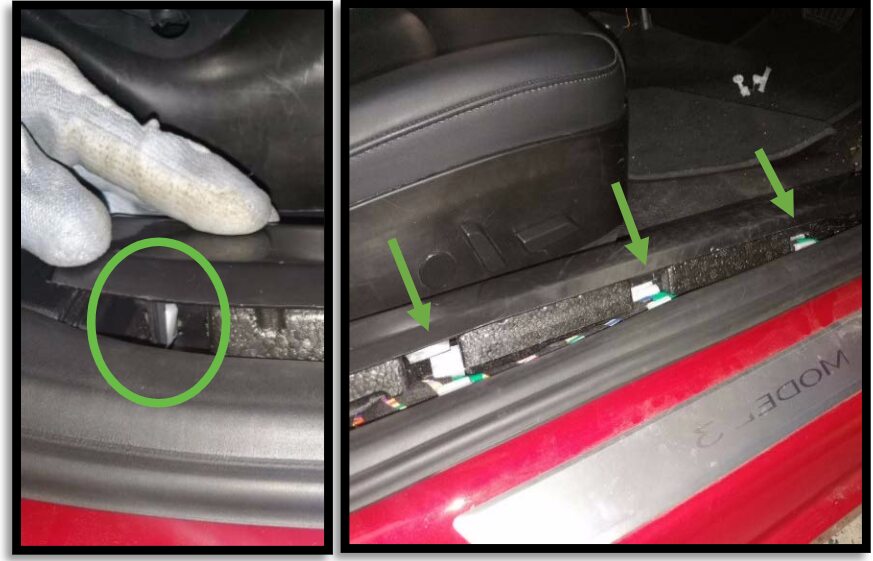
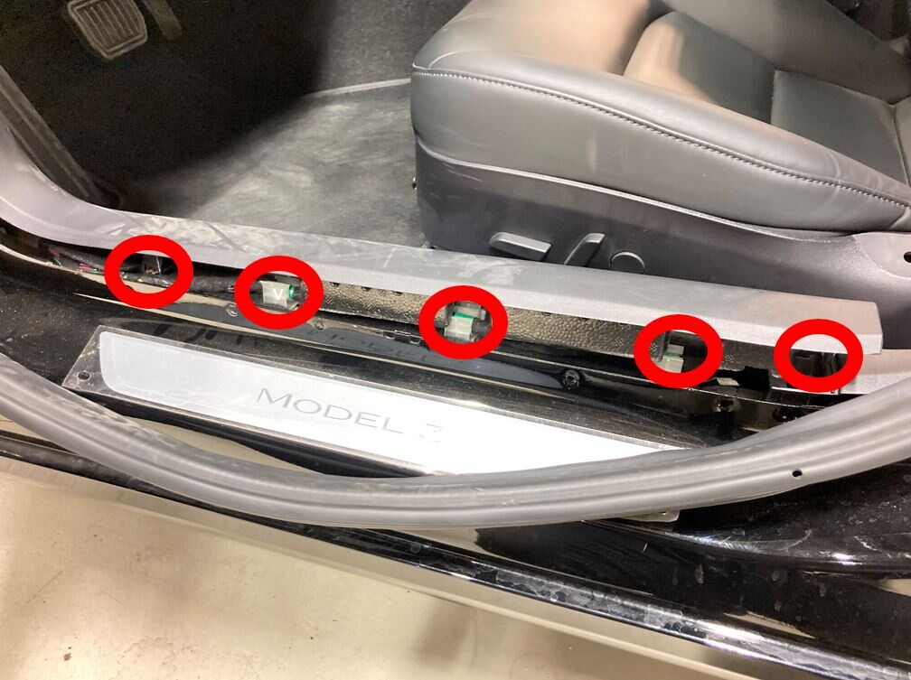
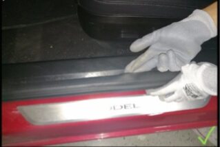
Remove the RH rear door sill trim
panel.
Remarque3x clips, 1x guide tab, Pull upward at the lower corner of sill trim to release clip from lower B-pillar, then remove the remaining clips by pulling away from the body.
-
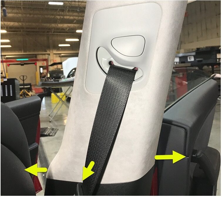
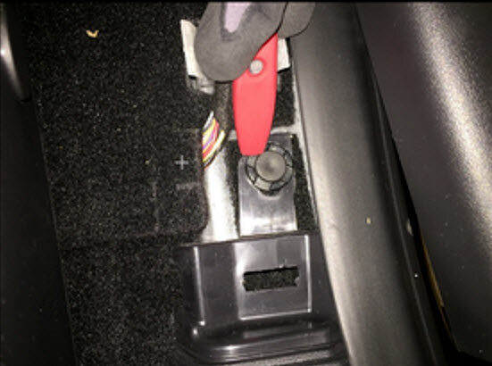
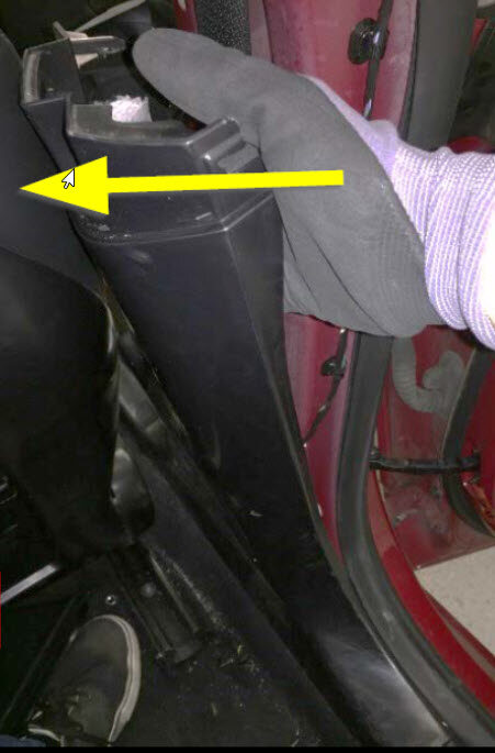
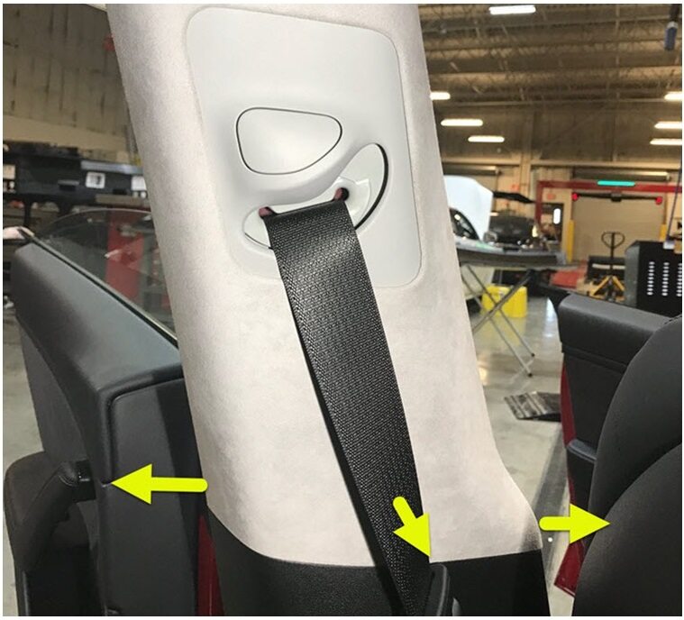
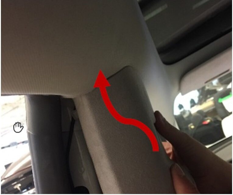
Release clips securing the RH upper
B-pillar assembly and move aside.
Remarque4x clips, Pull the bottom of the upper B-pillar toward inside of the car, then pull the top of trim to release the remaining clips.
-
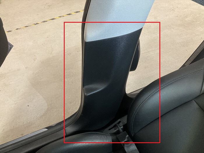
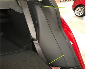
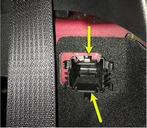
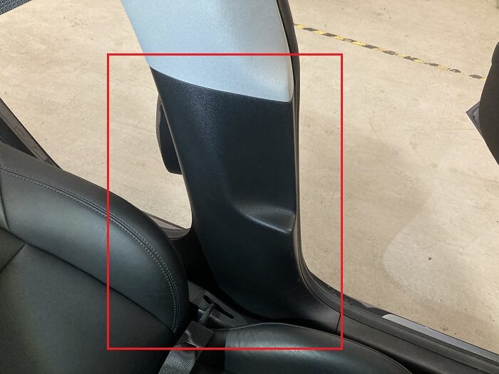
Remove the RH lower B-pillar
assembly.
Remarque1x push clip, 6x clips, Remove the front push clip from lower B-pillar, then pull the top of B-pillar to release top clips then work your way to bottom clips.
-
Fold the 60 seat in down
position.
RemarqueProtect the seat cushion.

-
Remove LH side bolster.
Remarque1x clip, 1 tab, Pull outward then slightly upward to remove.
-
Remove and discard bolster plastic
bracket from LH side.
Remarque2x clips, If necessary, depress the clips from behind, this bracket may come out with bolster. Discard after removal.
-
Fold the 60 seat into vertical
position.
RemarqueRemove seat protection.
-
Remove the LH rear door sill trim
panel.
Remarque3x clips, 1x guide tab, Pull upward at the lower corner of sill trim to release clip from lower B-pillar, then remove the remaining clips by pulling away from the body.
-
Release clips securing the LH upper
B-pillar assembly and move aside.
Remarque4x clips, Pull the bottom of the upper B-pillar toward inside of the car, then pull the top to release the remaining clips.
-
Remove the LH lower B-pillar
assembly.
Remarque1x push clip, 6x clips, Remove the front push clip from lower B-pillar, then pull the top of B-pillar to release top clips then work your way to bottom clips.
-
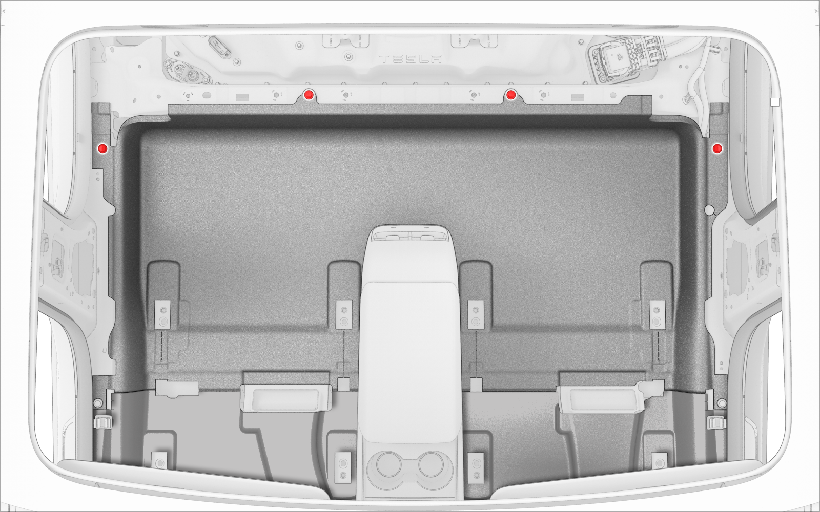
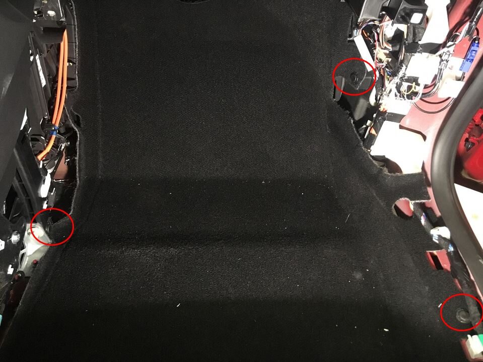
Remove clips securing rear main cabin
carpet to vehicle.
Remarque4x push clips, Velcro strips, The number of clips on newer vehicles may vary.
- Move LH front seat backward.
-
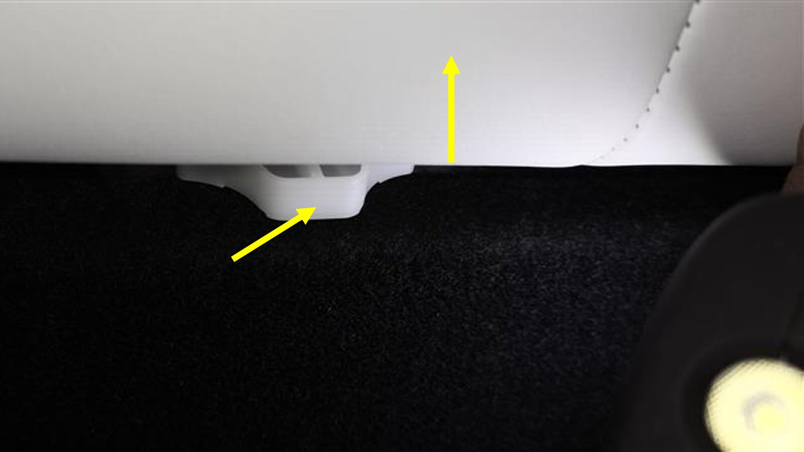
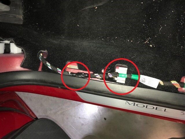
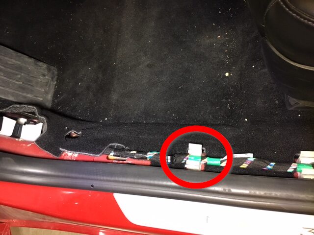
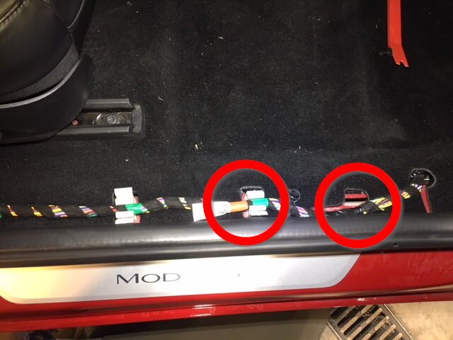
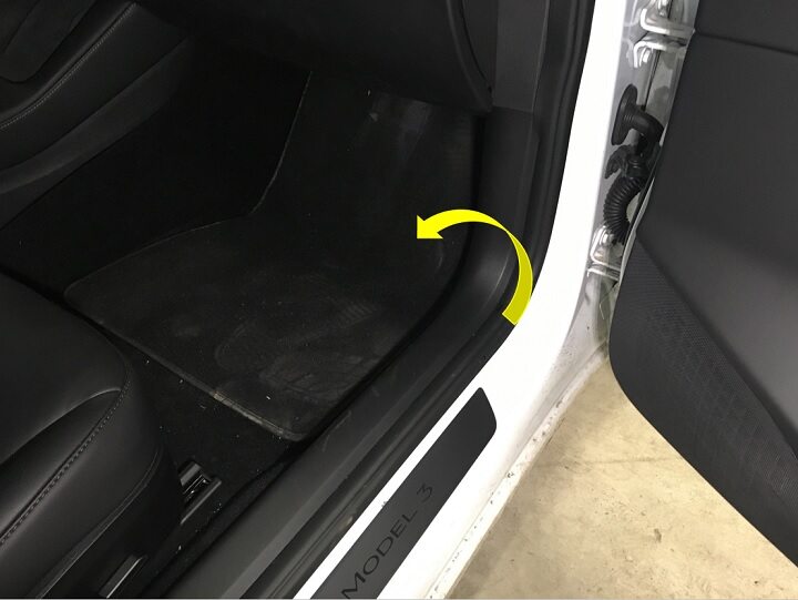
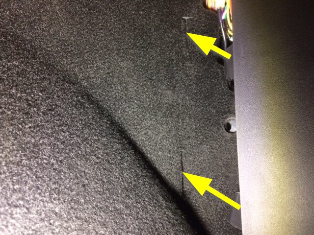
Remove clips securing LH front main
carpet to vehicle.
Remarque3x clips, Number of clips on new vehicles may vary.

-
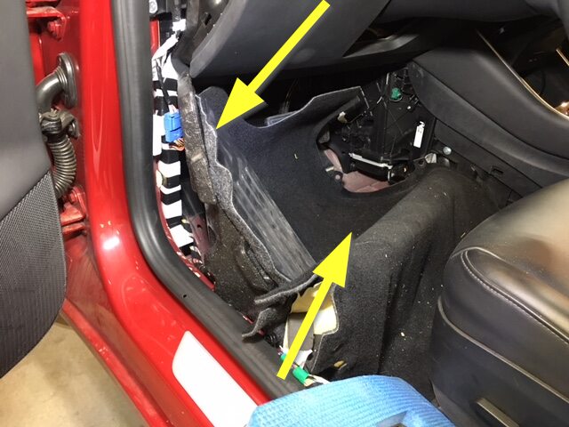
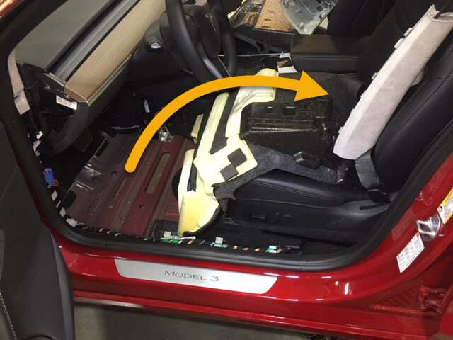
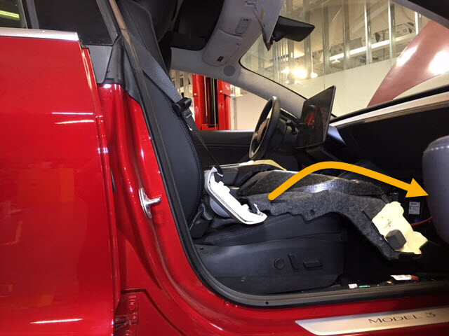
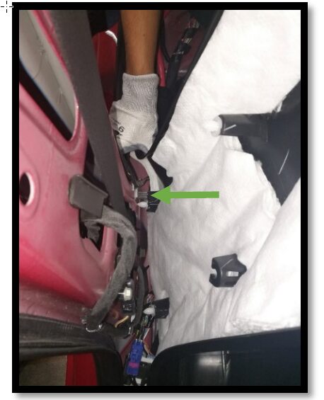
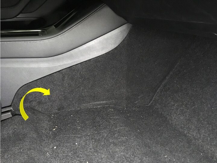
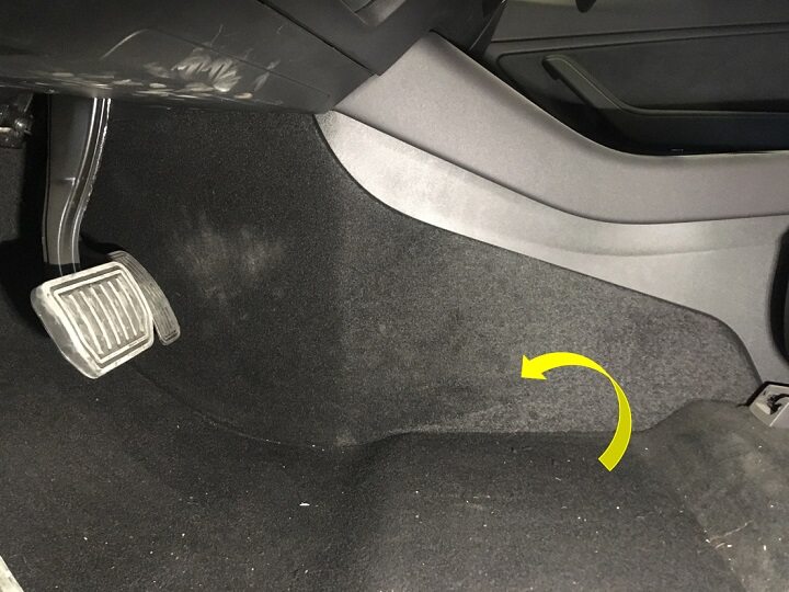
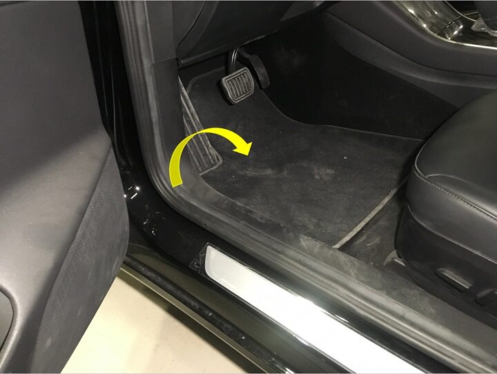
Fold the LH front main cabin carpet
aside for access.
RemarqueDead pedal and foam block are part of carpet, Release seat harness from clip to allow the carpet to fold back more.
-
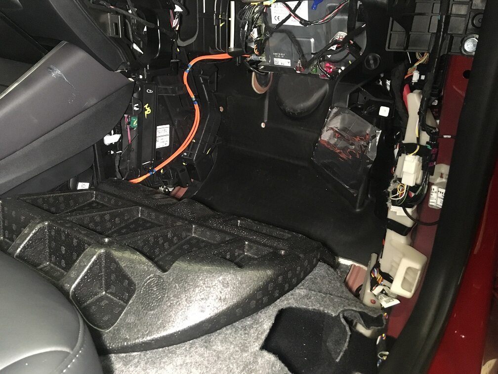
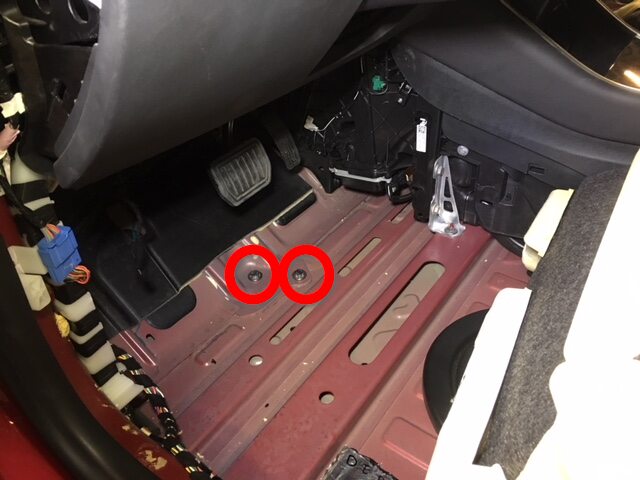
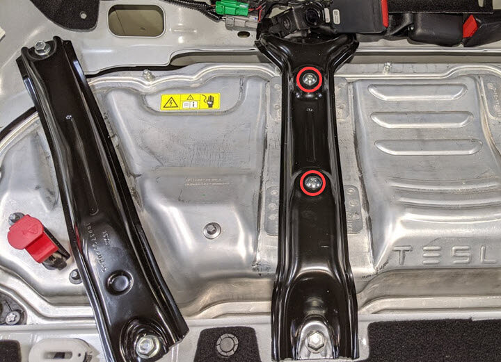
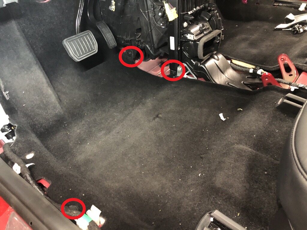
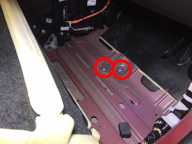
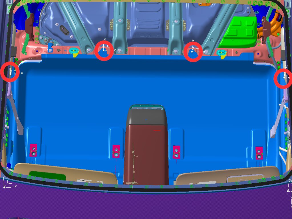
Remove LH front footwell HV battery
bolts.
Remarque2x bolts, EP20, 136 Nm.

-
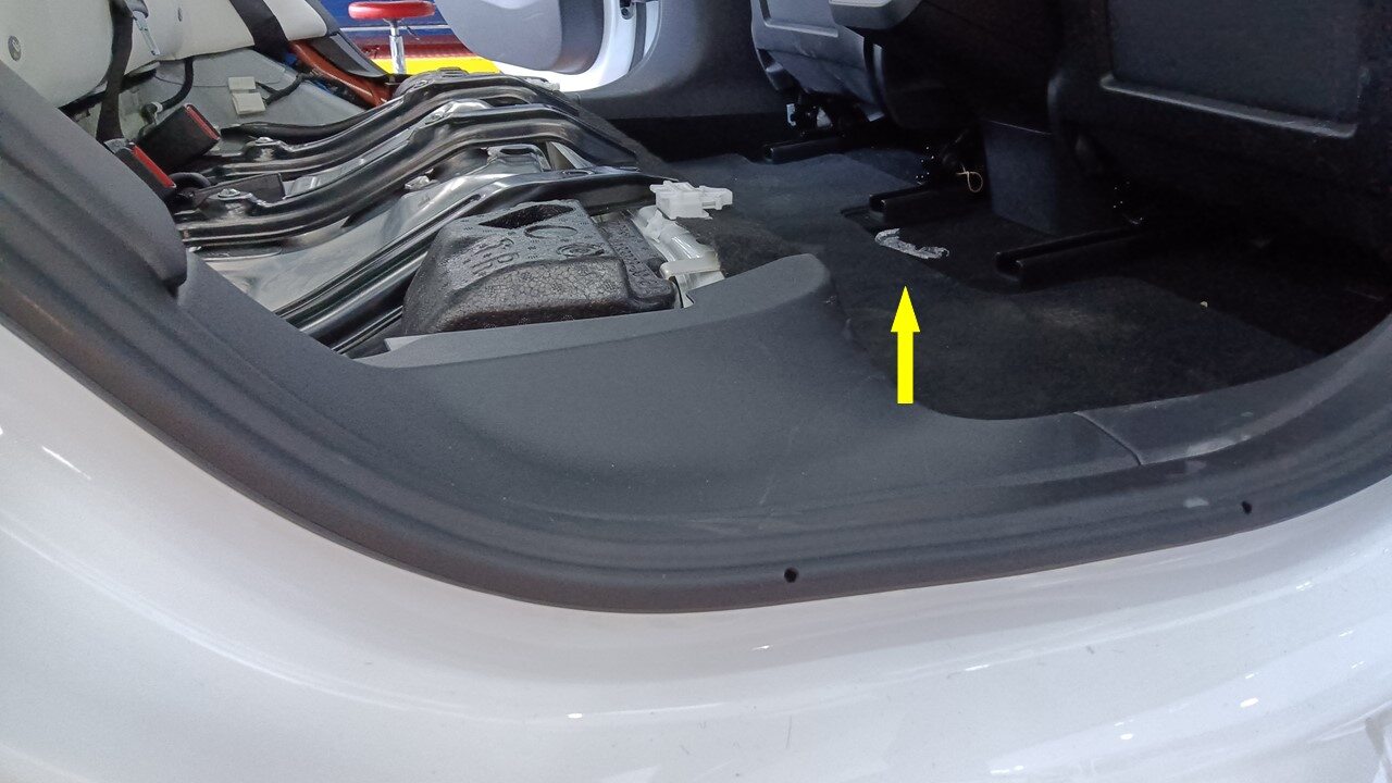
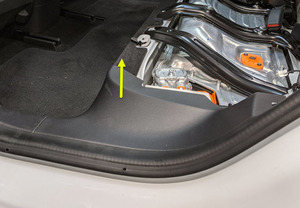
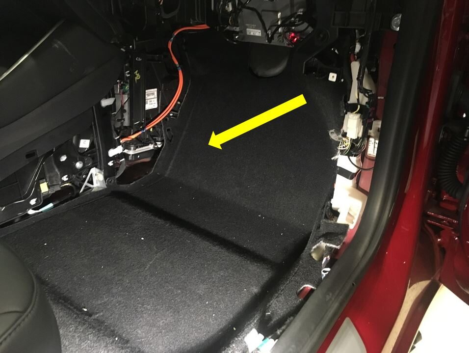
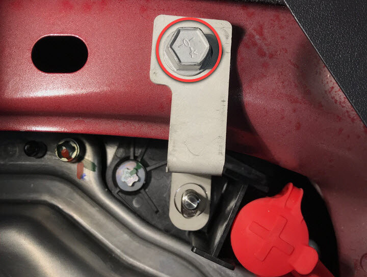
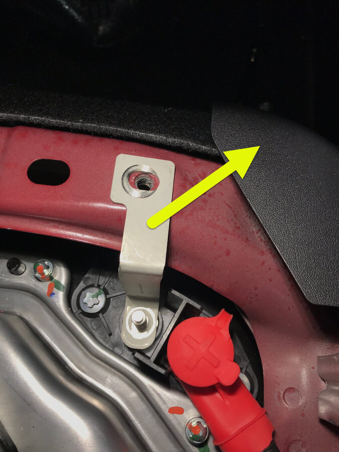
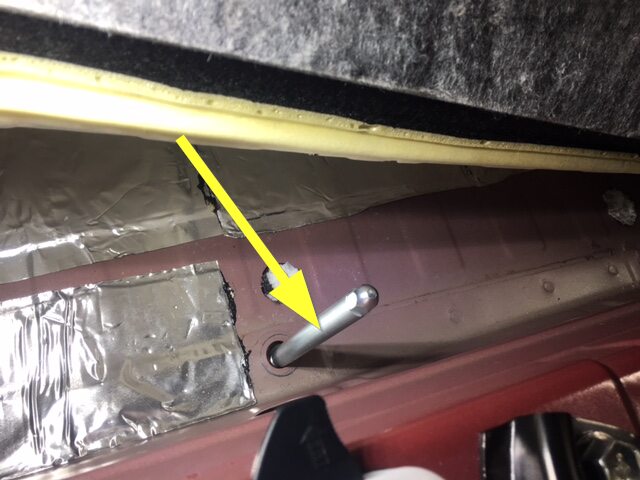
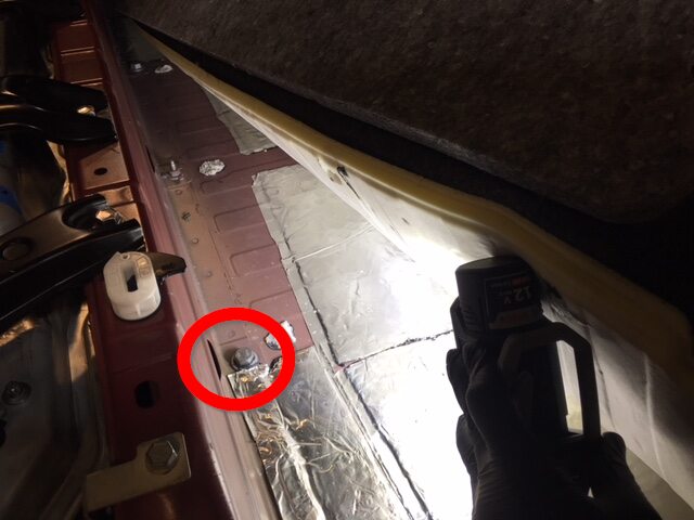
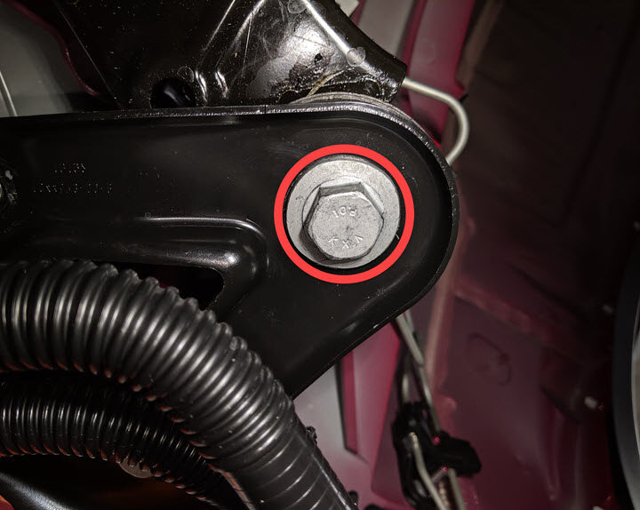
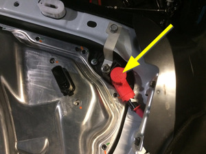
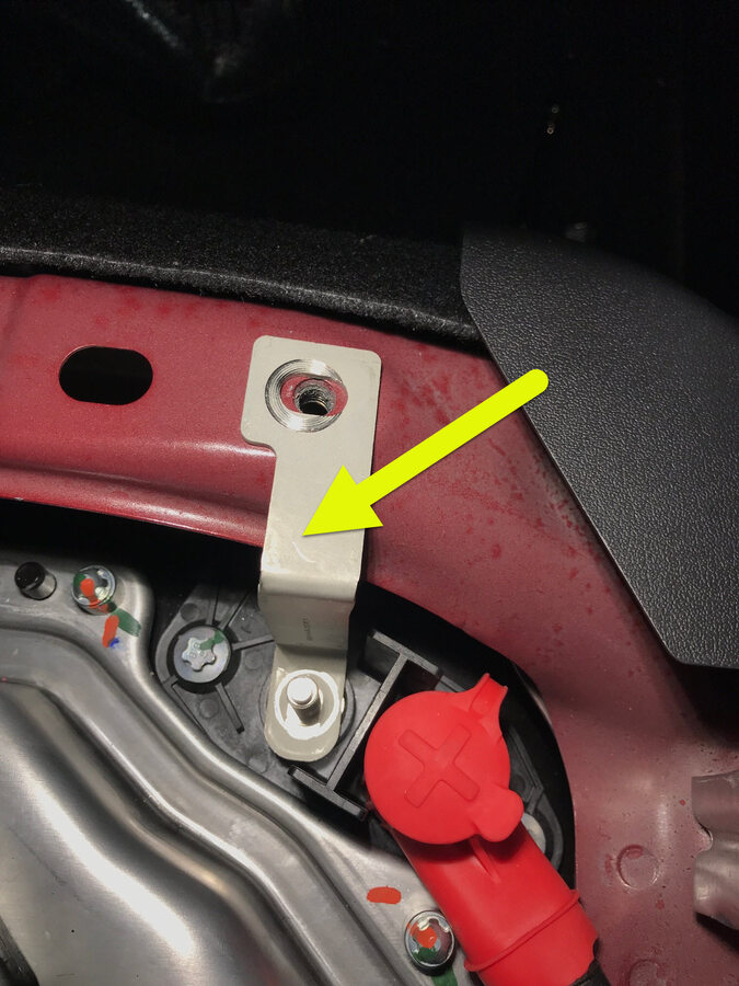
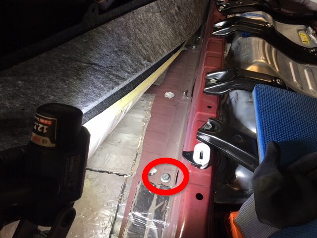
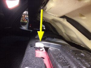
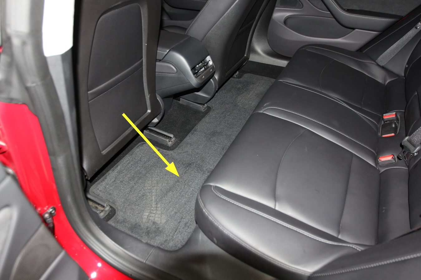
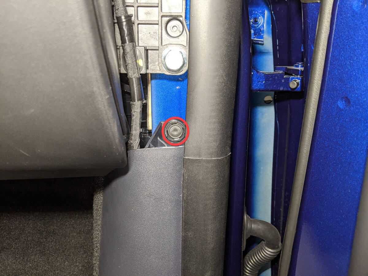
Remove LH rear HV battery interior
bolt.
Remarque1x bolt, 16mm, 66 Nm, Lift up carpet for access.

- Move RH front seat backward.
-
Remove clips securing RH front main
cabin carpet to footwell area.
Remarque3x push clips, Number of clips may vary on older vehicles.

-
Fold RH front main cabin carpet aside
for access.
Remarque2x clips, Lift center piece and pull carpet back, Release seat harness from clips to allow carpet to fold back more.
-
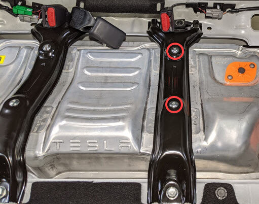
Remove RH front footwell HV battery
bolts.
Remarque2x bolts, EP20, 136 Nm.

-
Remove RH rear HV battery interior
bolt.
Remarque1x bolt, 16mm, 66 Nm, Lift up carpet for access.

-
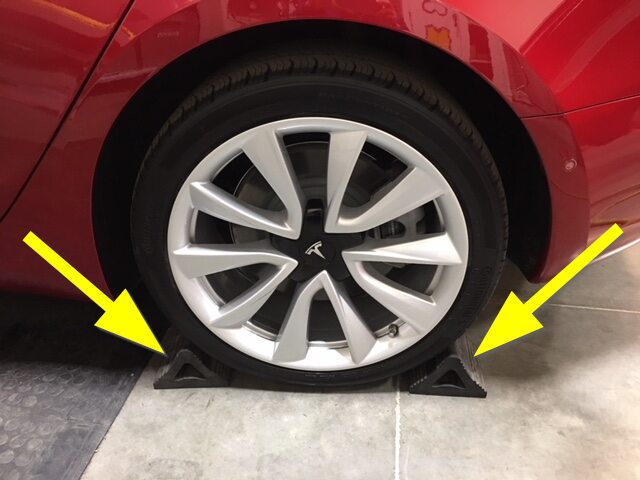
Place wheel chocks to keep vehicle
from moving.
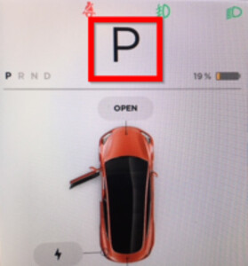
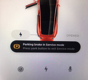
- Enable the EPB Service Mode. See Frein de stationnement - étrier - arrière - gauche (relâcher)
-
Power off vehicle from center
display.
RemarqueVia Controls > Safety & Security > Vehicle Power > Power Off, Confirm power off at warning dialogue box.
-
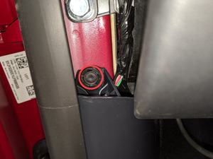
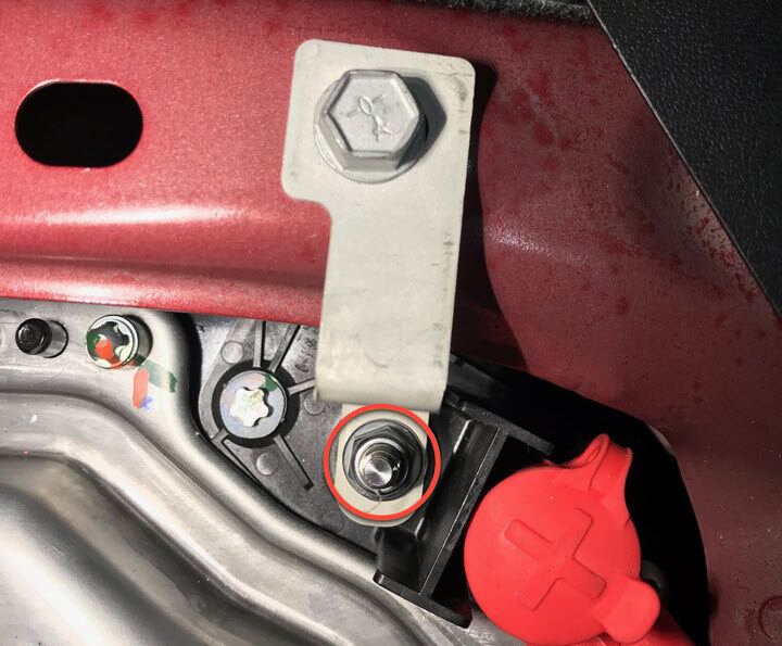
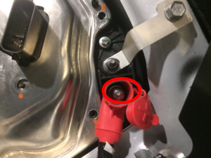
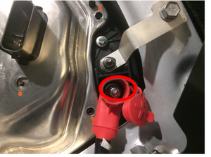
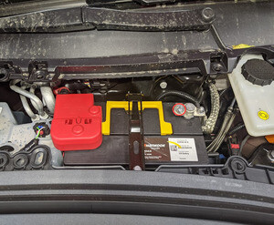
Disconnect 12V negative terminal.
Remarque1x nut, 10mm, 6 Nm, Ensure the vehicle is in park, climate control system is off, and vehicle is not charging before disconnecting 12V.

-
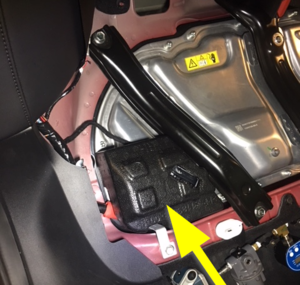
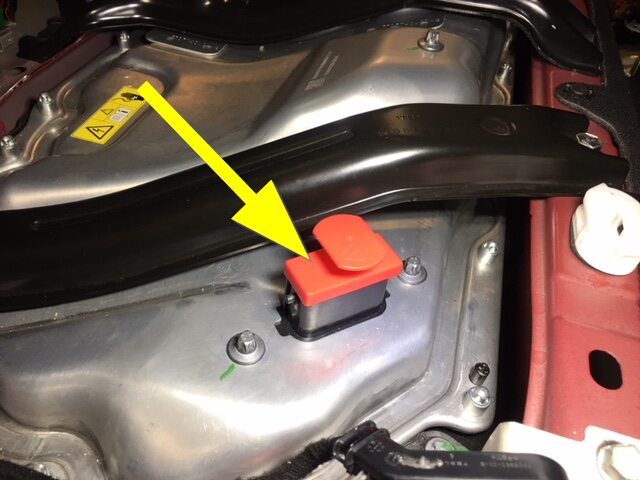
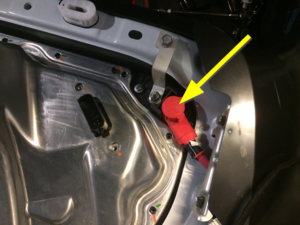
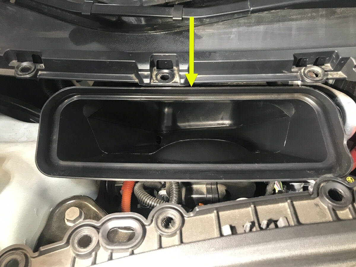
Remove 12V cap from ancillary bay.
Remarque1x cap.
-
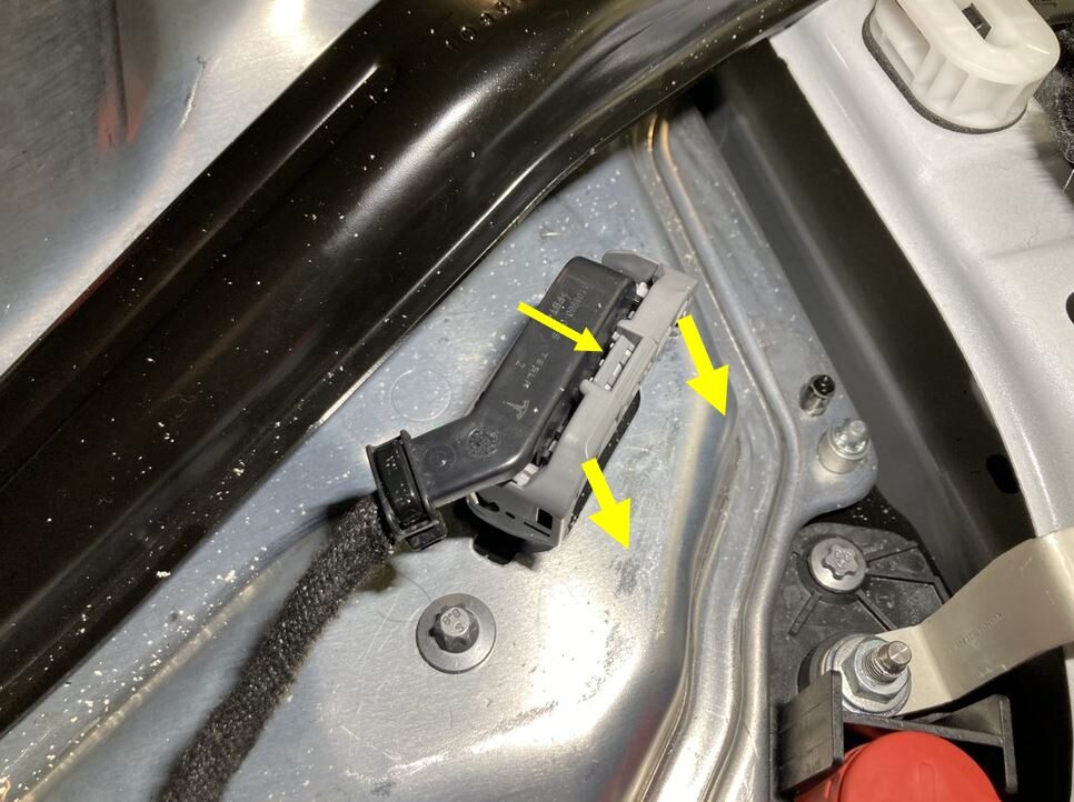
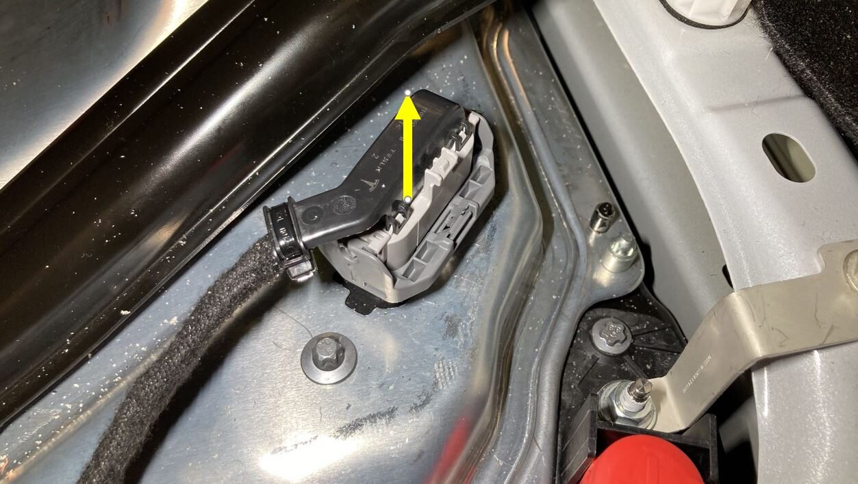
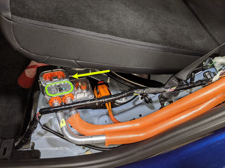
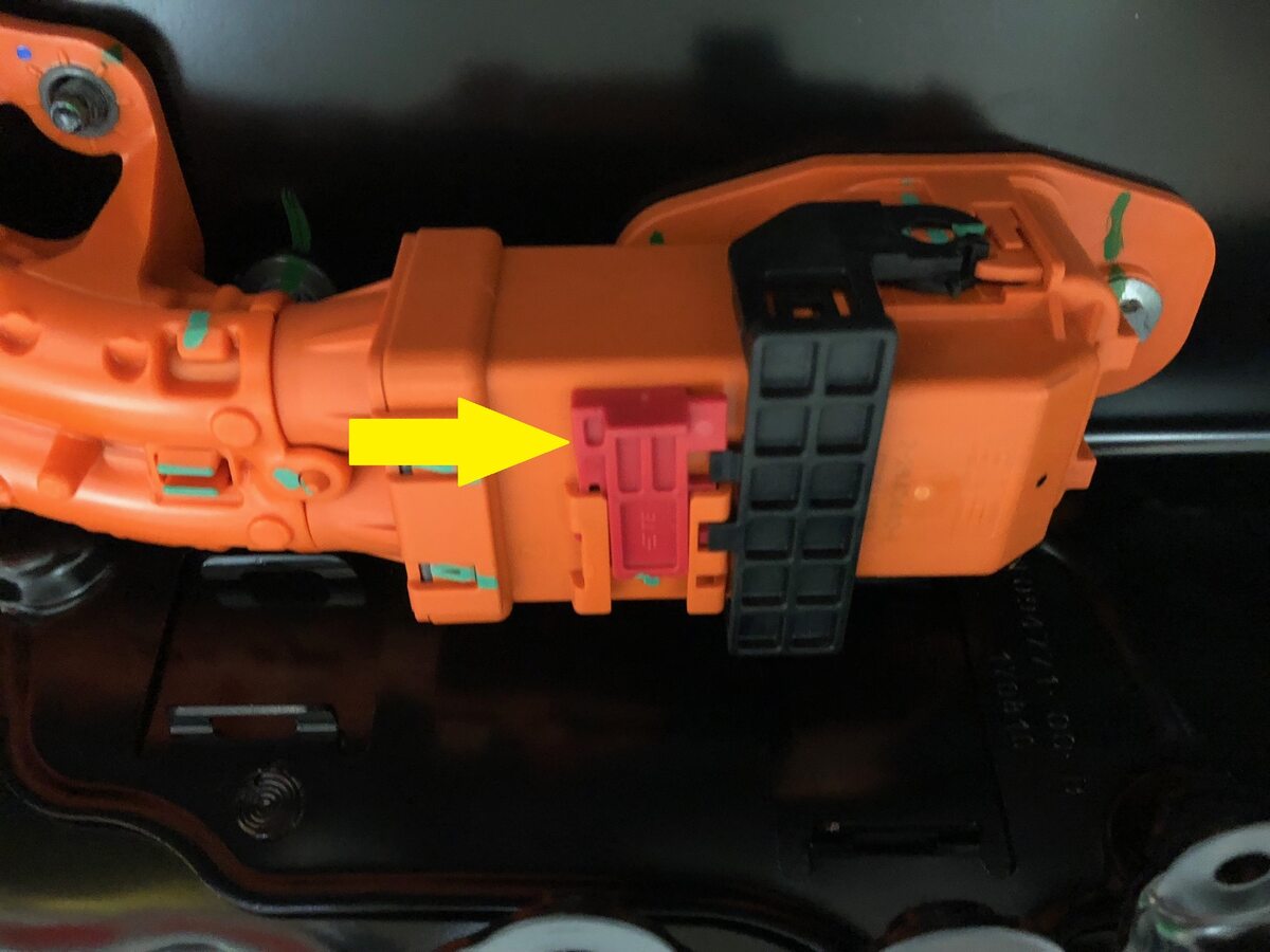
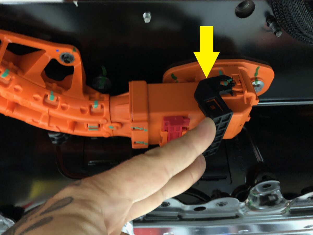
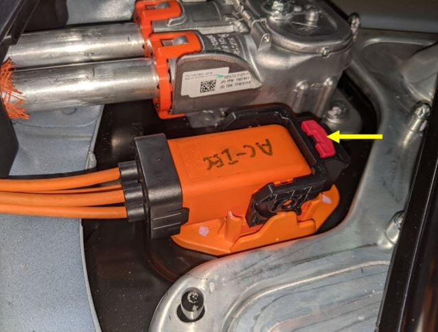
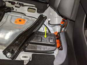
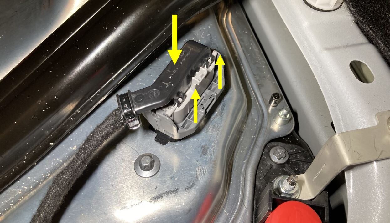
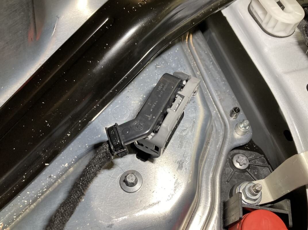
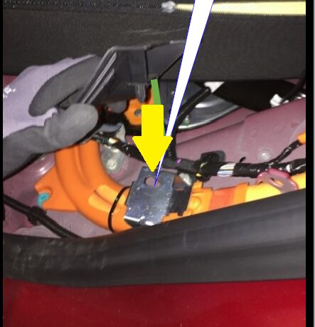
Disconnect HVC logic connector and
install logic cap.
Remarque1x connector, 1x cap, Release locking tab then push the handle downward to release connector.
- Remove all items from pockets and ensure not wearing metal items.
-
Inspect HV insulating gloves.
RemarqueCheck gloves for damage prior to each use, Refer to service document TN-15-92-003 R5, for information on inspecting HV gloves.
-
Put on HV insulating gloves and
leather over gloves.
RemarqueMake sure to wear Electrical Protective Gloves any time Hioki tester is used.
- Perform a charge port voltage check. See Vérification de la tension du port de recharge.
-
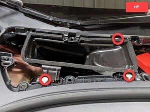
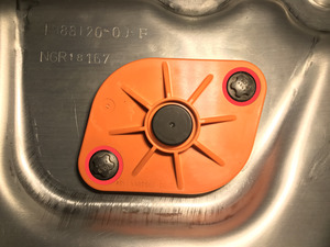
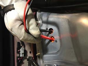
Remove bolts securing ancillary bay probe
lid cover to ancillary bay cover.
Remarque2x bolts, EP10 5-Lobe, 6 Nm, Discard after removal.
-
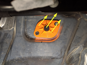
Remove ancillary bay probe lid cover from
ancillary bay cover.
-
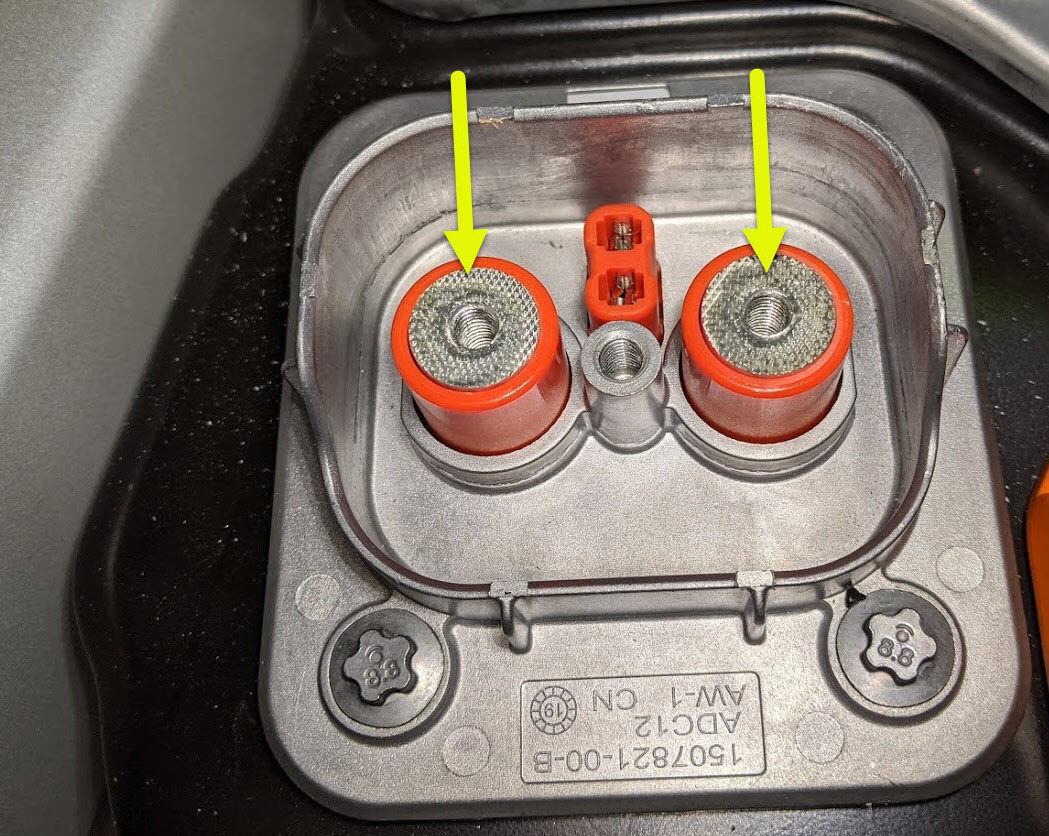
Verify no high voltage.
RemarqueMake sure to wear PPE (HV gloves, safety glasses) when working on high voltage component, Measure B+ to Ground, B- to Ground, B+ to B-, If voltage is greater than 10V, Pack contactors are not open or welded, Stop work and reach out to Service Engineering.


-
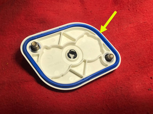
Inspect ancillary bay probe lid cover
gasket then position onto the ancillary bay cover.
RemarqueConfirm no damage is present, Seal can be re-used.
-
Install bolts securing ancillary bay probe
lid cover to ancillary bay cover.
Remarque2x bolts, E10 5-Lobe, 6 Nm, Install new fasteners.

-
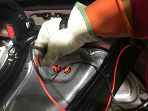
Remove HV cap from ancillary bay.
Remarque1x cap.
-
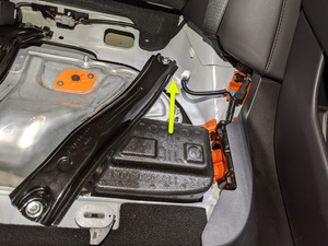
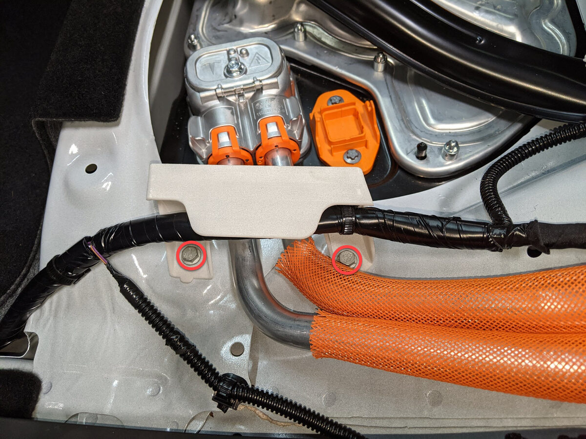
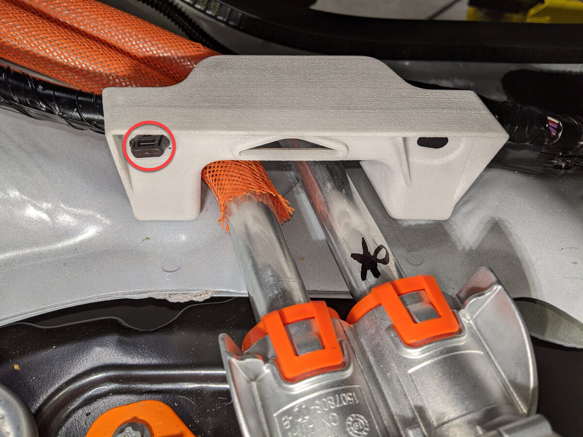
Remove edge support bracket.
Remarque2x bolts, 10mm, 10 Nm, 1x clip.
-
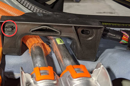
Remove fastener securing busbar cover
access door.
Remarque1x bolt, 10mm, 9 Nm.

-
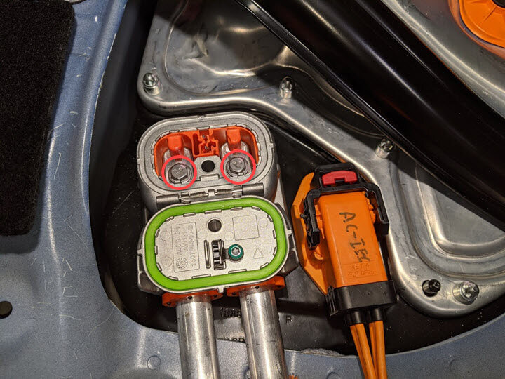
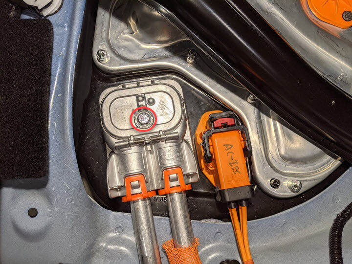
Remove bolts securing chargeport
busbar to HV header.
Remarque2x bolts, 10mm, 9 Nm.
-
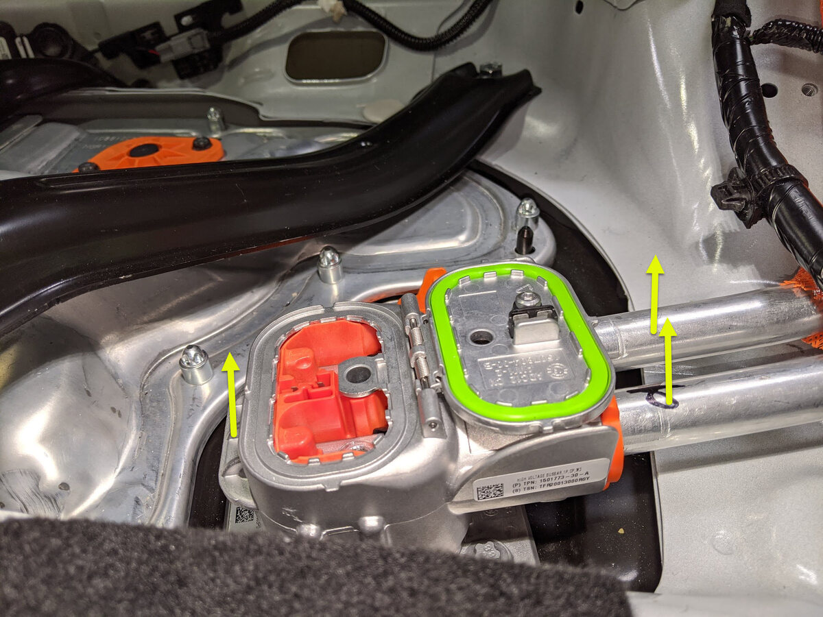
Lift chargeport busbar connector to
remove from HV header.
Remarque4x guide tabs, Slightly wiggle aluminum connector housing back and forth to ease removal.
-
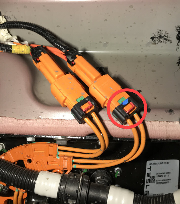
Disconnect 3PH chargeport inlet
harness from HV header.
Remarque1x connector, Release red locking tab and rotate lever arm to release.
-
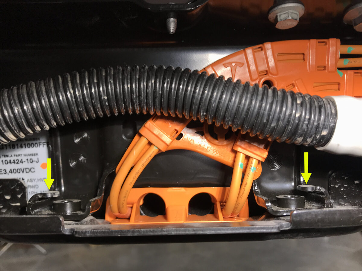
Remove bolts securing LH inner
ancillary bay rail to the ancillary bay cover.
Remarque2x bolts, T40, 24 Nm.

-
Remove bolts securing RH inner
ancillary bay rail to the ancillary bay cover.
Remarque2x bolts, T40, 24 Nm.

-
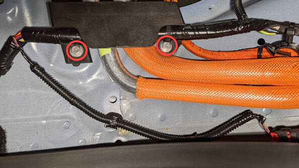
Remove nut securing DCDC ground busbar
to HV battery.
Remarque1x nyloc nut, 13mm, 9 Nm, Discard nut after removal.
-
Remove bolt securing DCDC ground
busbar to body.
Remarque1x bolt, 13mm, 20 Nm.
-
Remove DCDC ground busbar.
-
Remove positive 12V output cover from
PCS cable.
Remarque1x cover.
-
Remove nut securing positive 12V
output from PCS cable and move cable aside.
Remarque1x nyloc nut, 13mm, 9 Nm, Discard nut after removal.
-
Close all four doors.
RemarqueMake sure all windows are lowered and rear doors are latched to prevent accidental closure when vehicle is powered down.
-
Push vehicle onto lift.
RemarqueRecommend assistance, Note this vehicle can only be safely pushed for a very short distance and at very slow speed.
-
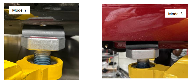
Installez les adaptateurs de coussin de levage.
- Pour la zone Europe, Moyen-Orient et Afrique uniquement, installez Adaptateur, coussinet rehausseur, Model 3 (1453419-00-A
- Pour les autres régions, installez les adaptateurs de coussin de levage universels (1936724-00-A)
AvertissementN'UTILISEZ PAS d'autres adaptateurs de plaques d’appui universels.RemarqueEn dehors de la zone Europe, Moyen-Orient et Afrique, les adaptateurs de coussin de levage universels (1936724-00-A) remplacent Adaptateur, coussinet rehausseur, Model 3 (1453419-00-A. Jetez toutes les autres versions d’adaptateurs de coussin de levage.RemarqueDans la zone Europe, Moyen-Orient et Afrique, les adaptateurs universels pour coussins de levage ne sont pas encore disponibles. Assurez-vous d'utiliser les coussins de levage en caoutchouc du modèle Y sur le modèle Y et les coussins de levage du modèle 3 sur le modèle 3.Instructions pour les adaptateurs de coussins de levage universels :
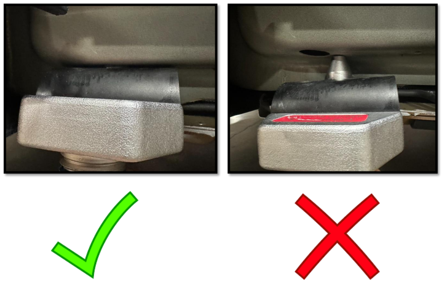
- En fonction du type de levage, installez l'adaptateur fileté approprié sur l'adaptateur de levage.
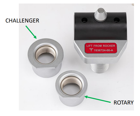
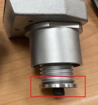
- Assurez-vous que la rondelle d'arrêt filetée est installée et serrée au bas de l'adaptateur de levage. Si la rondelle d'arrêt de filetage n'est pas installée, ne continuez pas à utiliser l'adaptateur de levage.
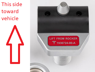
- Placez les adaptateurs de levage sur les bras de levage de sorte que le coussin de levage noir soit orienté vers le véhicule.AvertissementVérifiez que l'adaptateur est installé dans le bon sens.
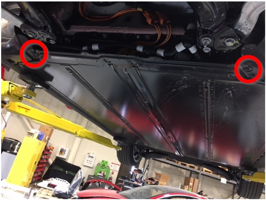
- Positionnez les bras de levage de manière à ce que les adaptateurs de levage s'alignent avec le trou de repère sur le véhicule.
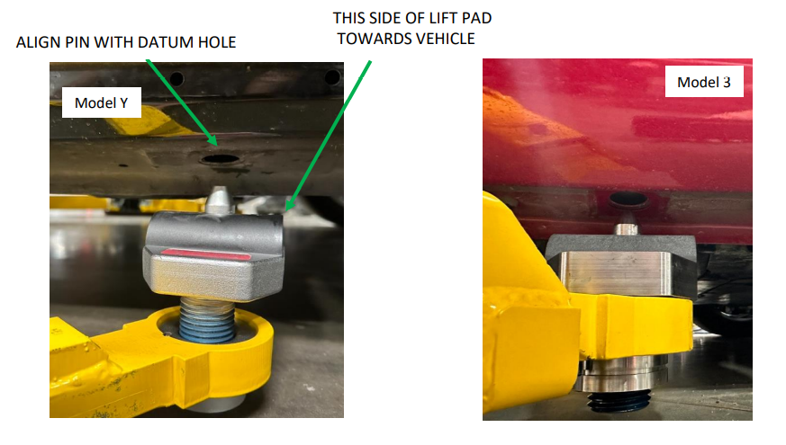
- Soulevez les bras de levage pour placer complètement les coussinets de levage dans le véhicule.
- Assurez-vous que les quatre adaptateurs sont bien insérés dans le véhicule.

- Raise and support vehicle.
-
Raise vehicle fully and lower lift
onto locks.
RemarqueSet vehicle to comfortable working height, Make sure there's an audible click of the locks on both sides before lowering, otherwise vehicle may tilt to the side, Verify doors are clear of surrounding objects.
-
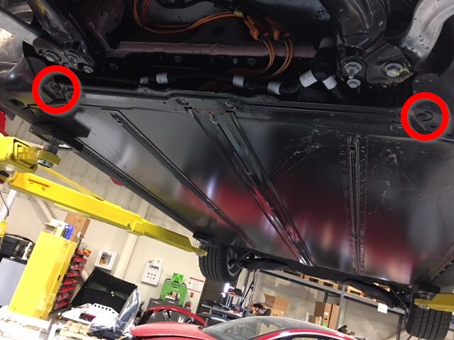
Remove outer fasteners securing front
aero shield.
Remarque9x bolts, 10mm, 5 Nm.

-
Remove remaining nuts and remove front
aero shield from vehicle.
Remarque2x nuts, 15mm, 5 Nm.

-
Remove the clips securing the front LH
and RH wheel liners to the front skid plate.
Remarque2x push clips.
-
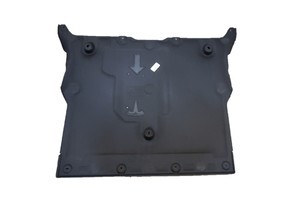
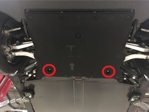
Remove bolts securing front skid
plate.
Remarque4x bolts, EP10, 13 Nm.
-
Remove skid plate from HV
battery.
-
Release connector from bracket.
Remarque1x connector.
-
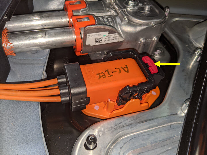
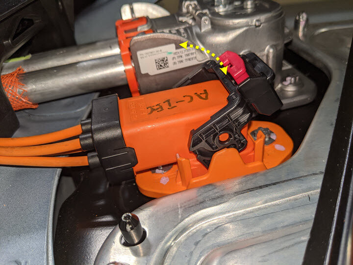
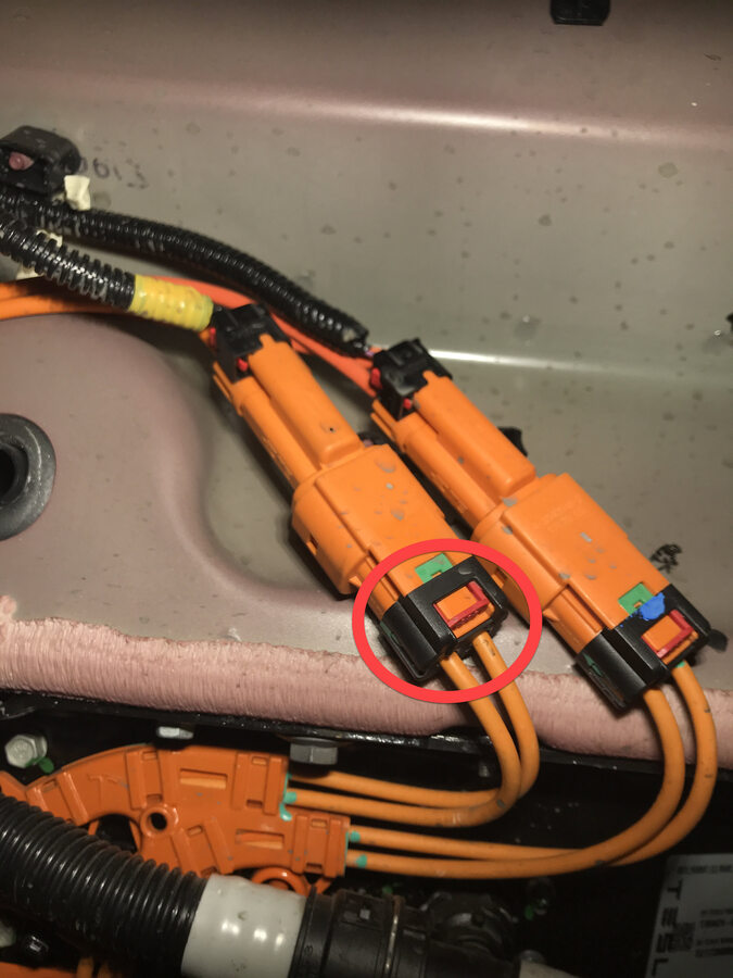
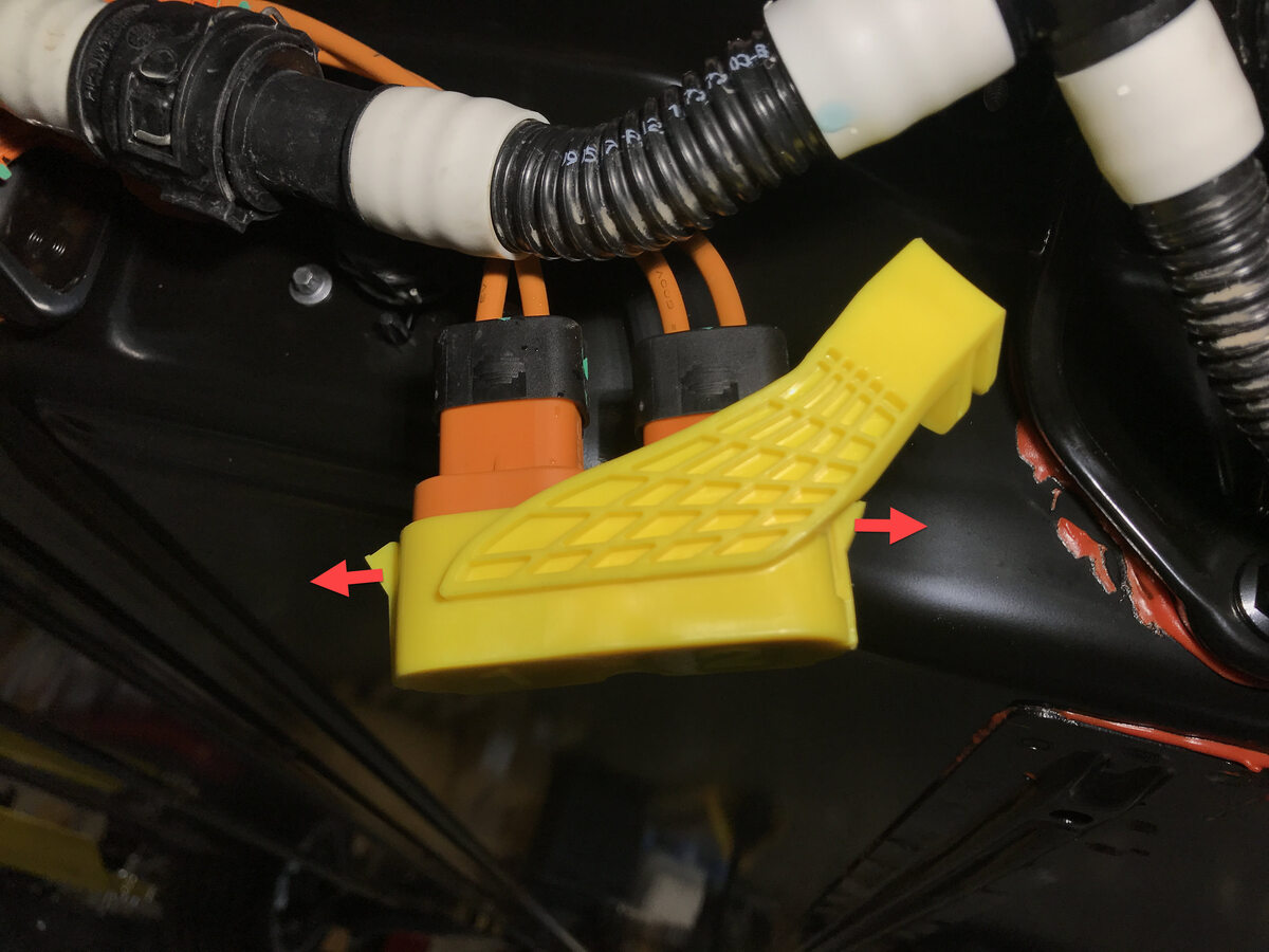
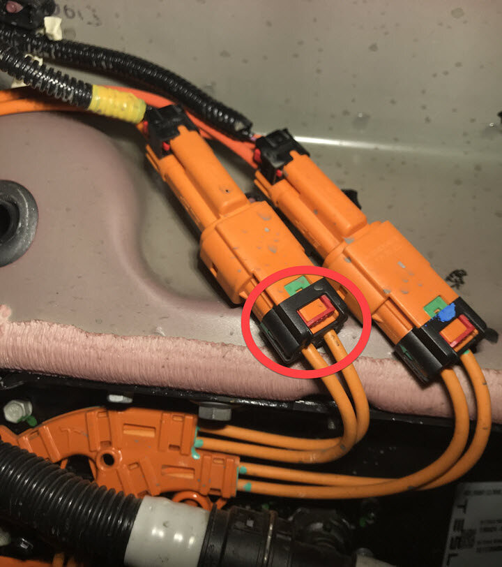
Disconnect A/C compressor HV harness
connector.
Remarque1x connector, 1x Red locking tab, 2 stage push release, Unlock by pulling back red tab, Push orange lip and pull back ''stage 1'', Push green lip and pull back to disconnect.
-
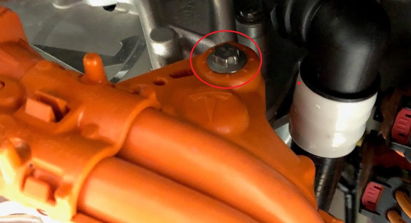
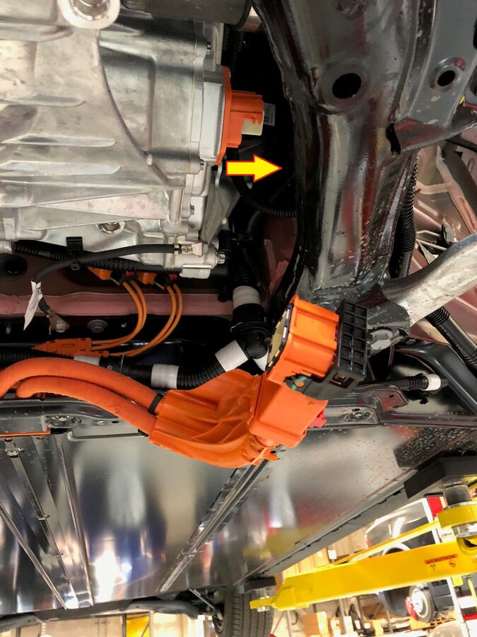
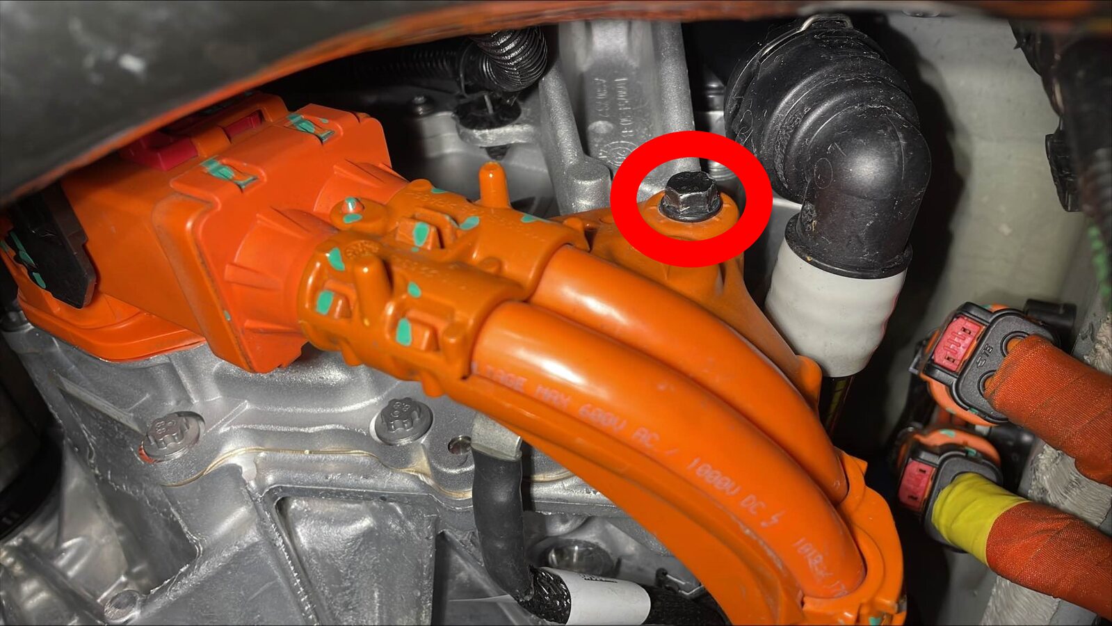
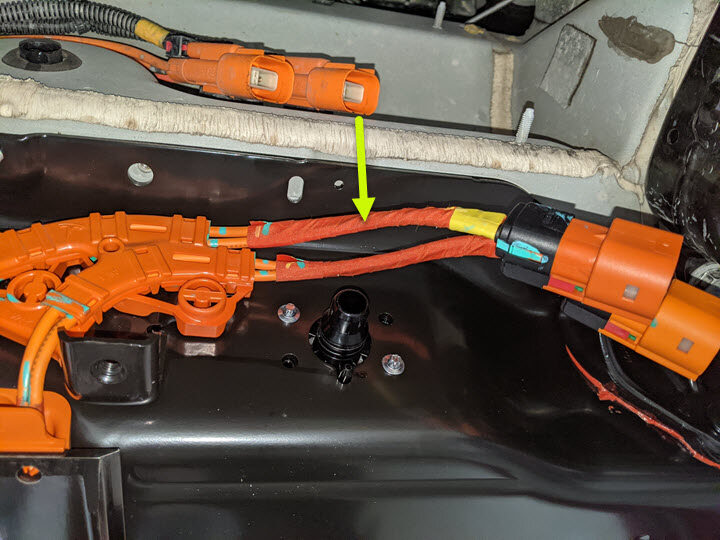
Remove bolt securing FDU HV harness to
FDU.
Remarque1x bolt, 10mm, 10 Nm.
-
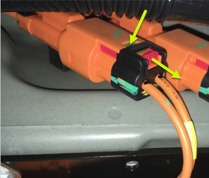
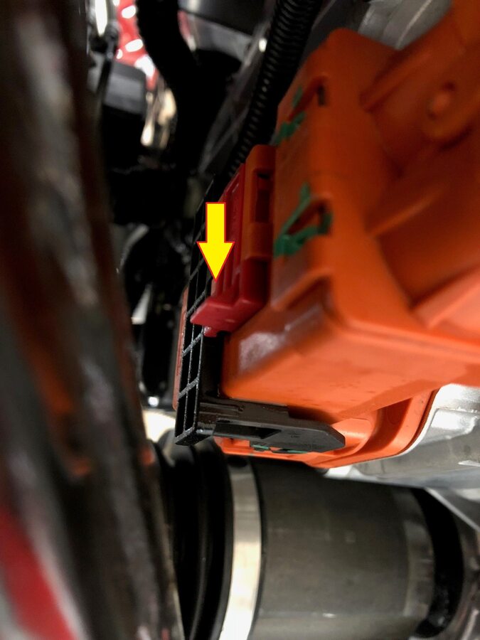
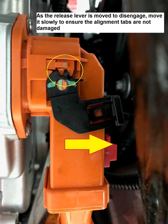
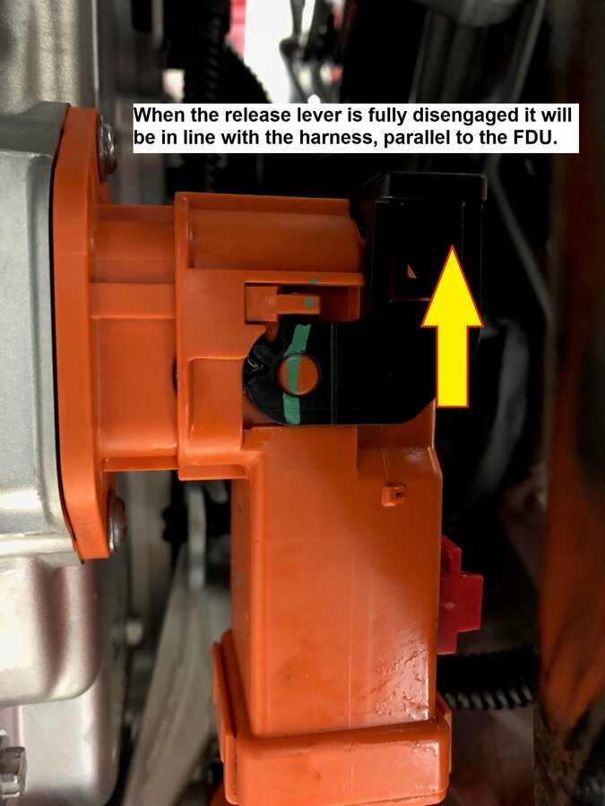
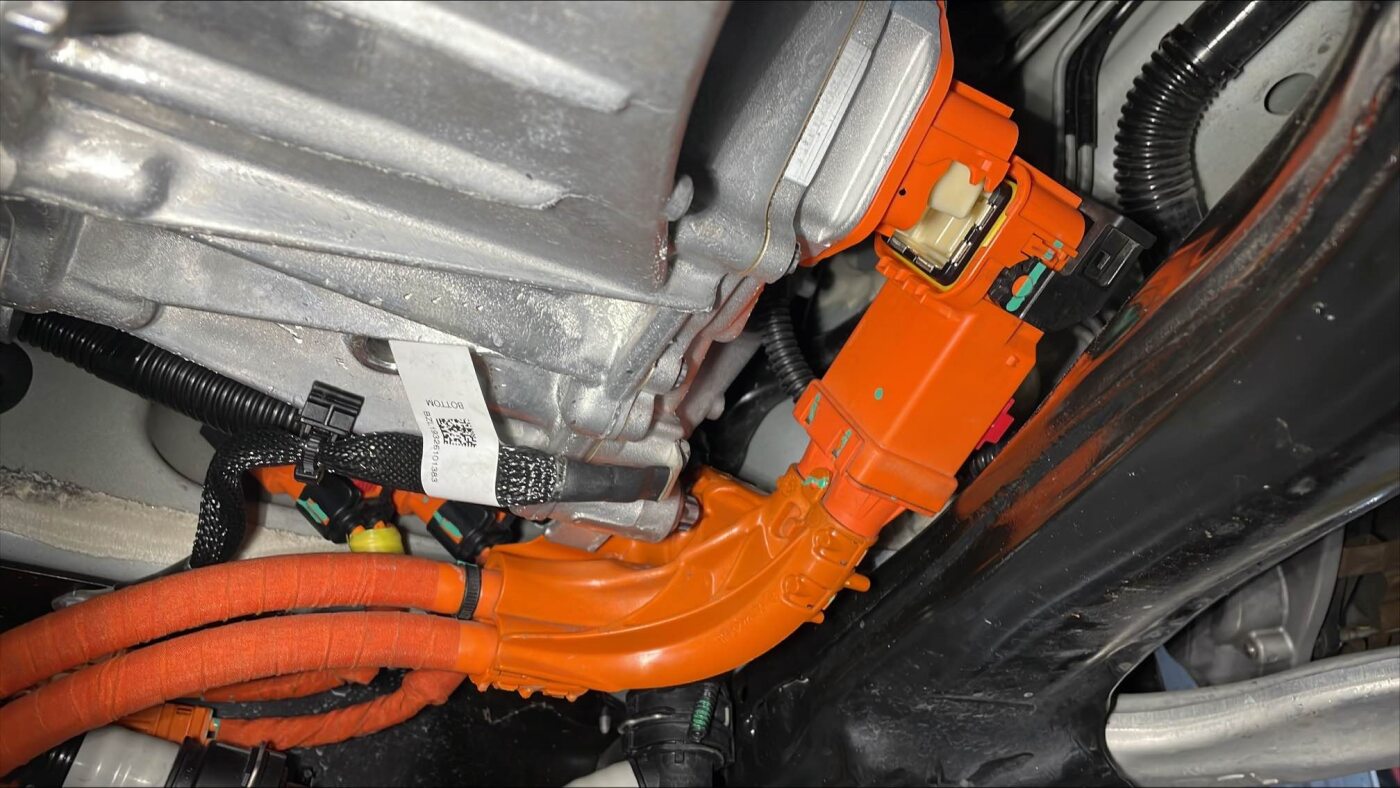
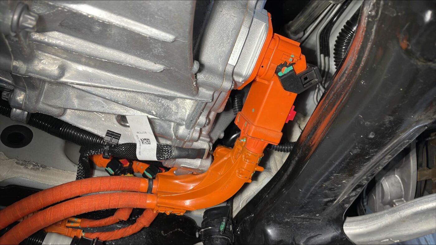
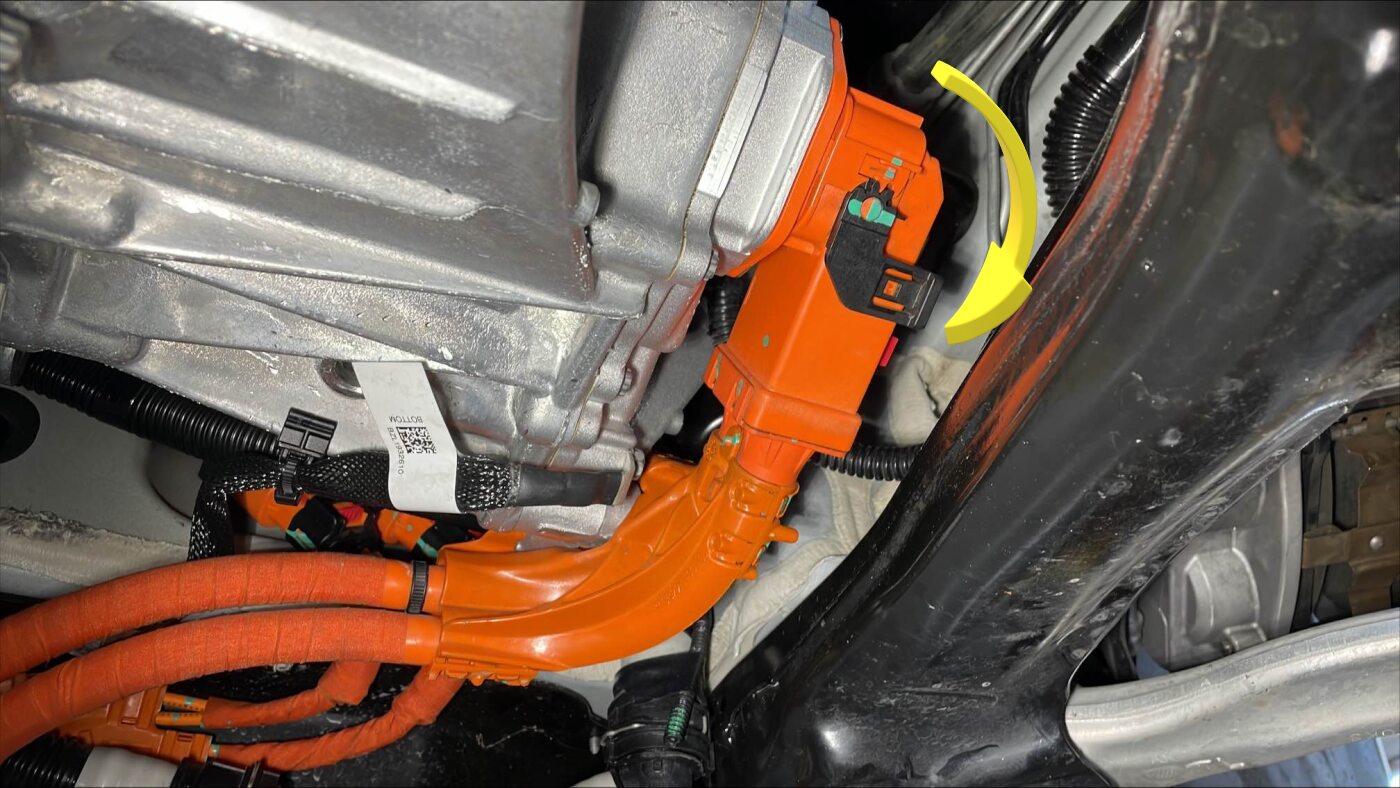
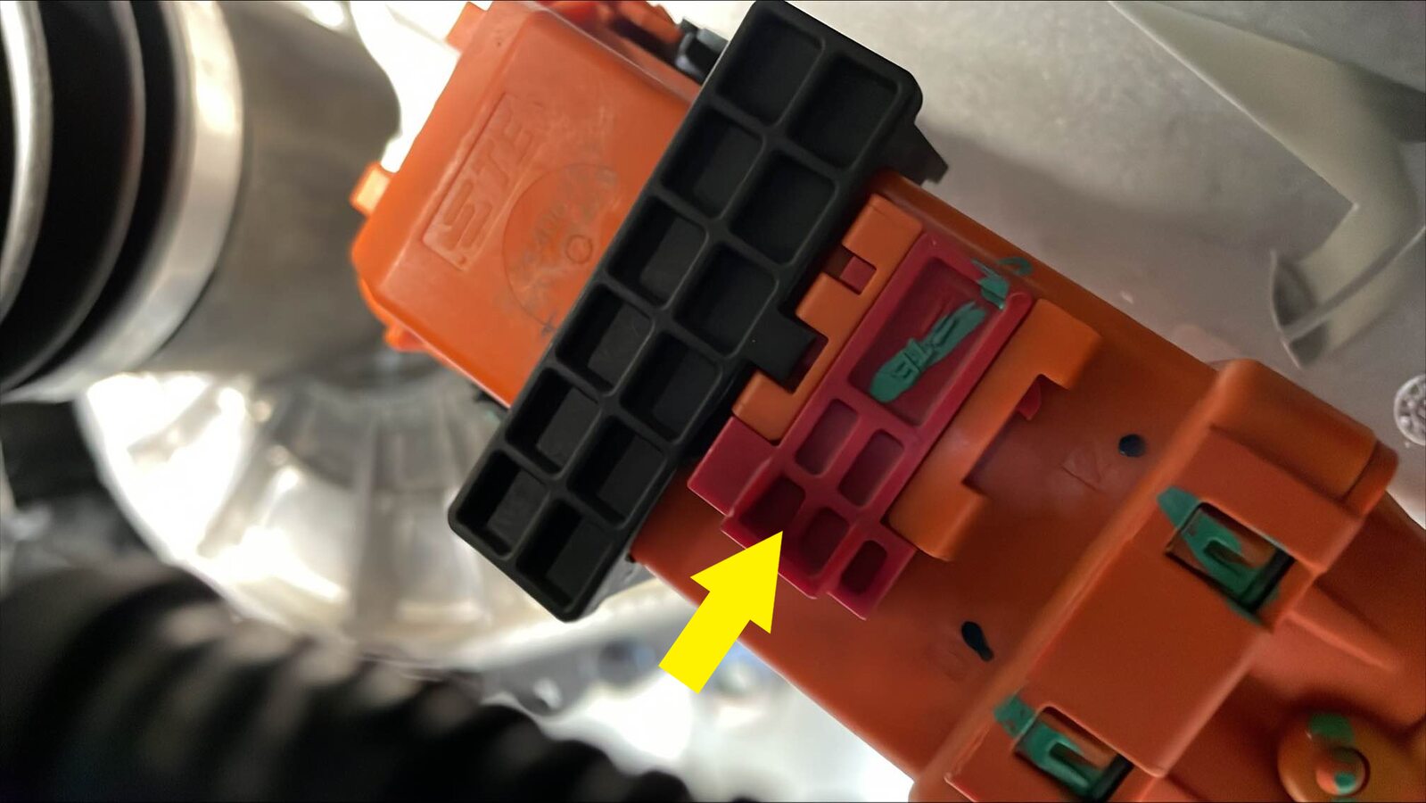
Disconnect the FDU HV harness
connector.
Remarque1x clip, Release locking tab and rotate the release lever up to disengage the connector, Do not force the release lever up, Ensure the alignment tabs on the FDU header are not damaged.
-
Remove the FDU HV harness connector
from the FDU and move aside.
Remarque1x connector.
-
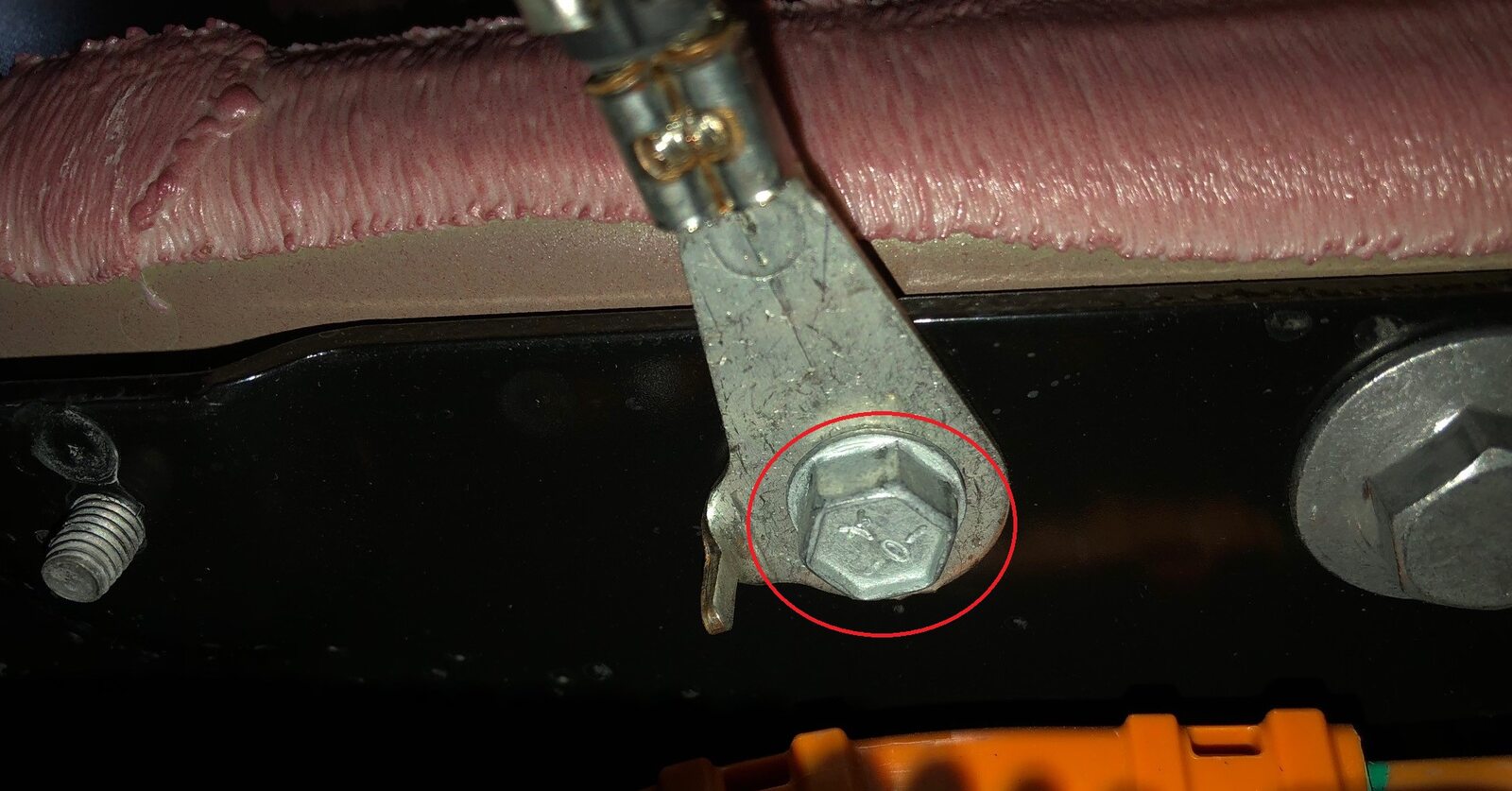
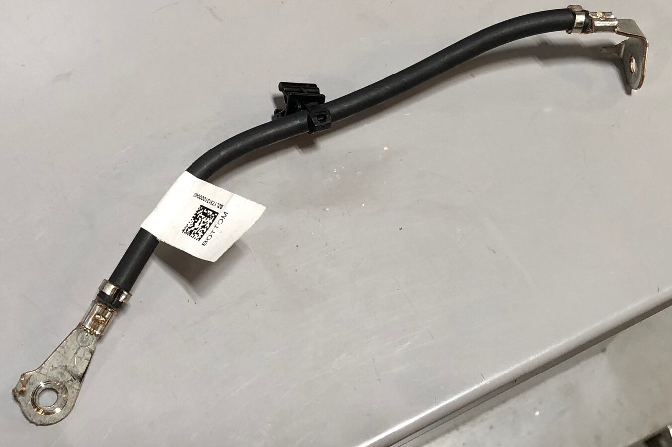
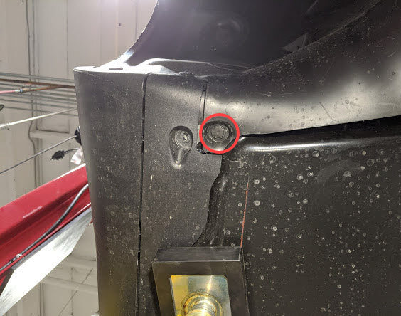
Remove FDU ground strap bolt from HV
battery and remove ground strap from vehicle.
Remarque1x bolt, 10mm, 10 Nm.
-
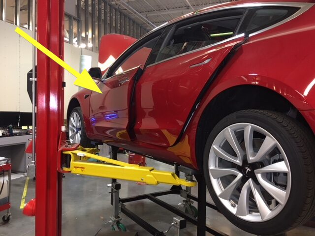
Remove push clip securing LH front
wheel liner to LH rocker panel.
Remarque1x push clip.
-
Remove push clip securing RH front
wheel liner to RH rocker panel.
Remarque1x push clip.

-
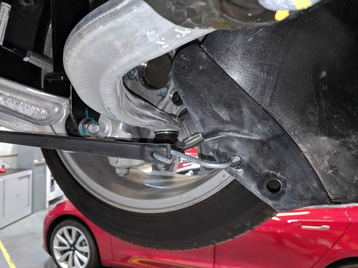
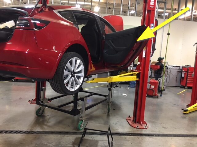
Use bungee strap to pull back LH front
wheel liner.
RemarqueSecure to subframe.
-
Use bungee strap to pull back RH front
wheel liner.
RemarqueSecure to subframe.
-
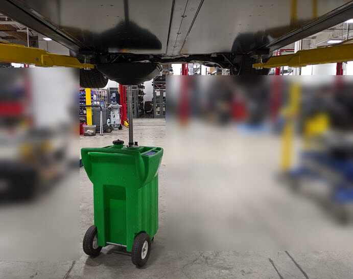
Position coolant drain container
underneath RH front of HV battery.
-
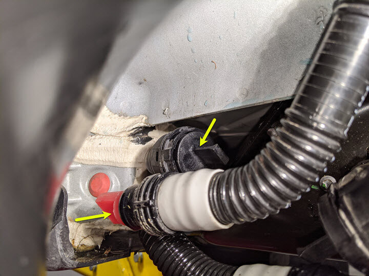
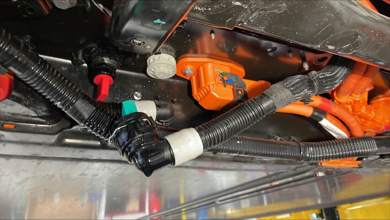
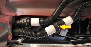
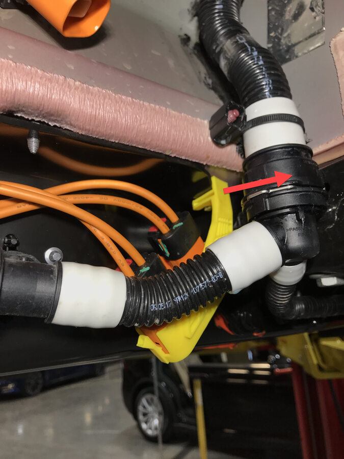
Release FDU Inverter Inlet hose RH
side of vehicle and plug both hoses.
Remarque1x hose clips, Plug both ends, Coolant loss greater than 1 L will require vacuum fill.

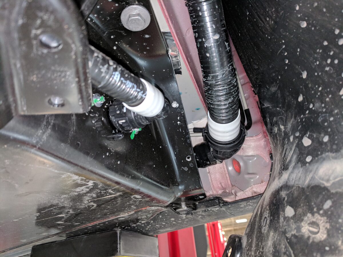
-
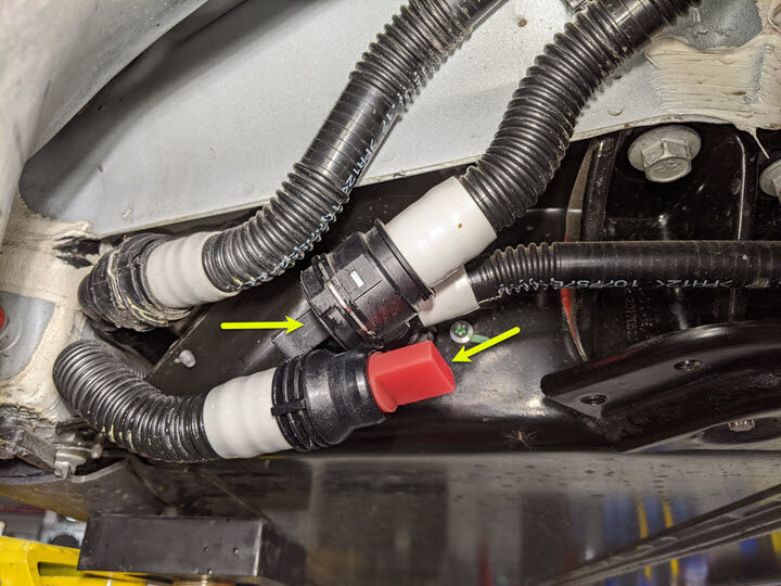
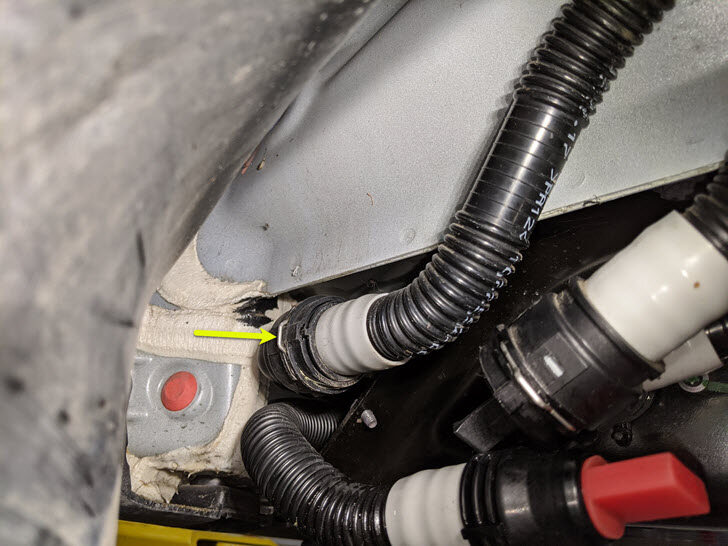
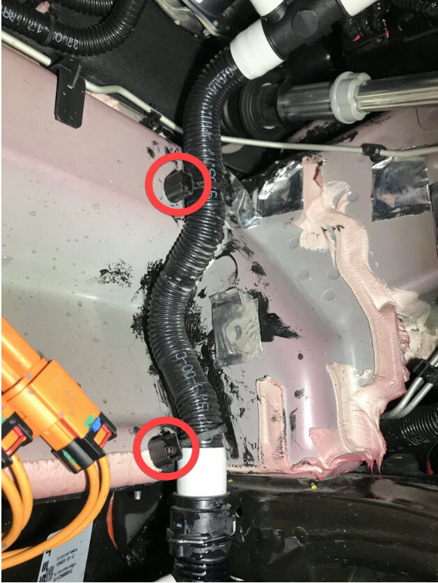
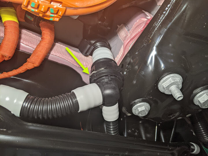
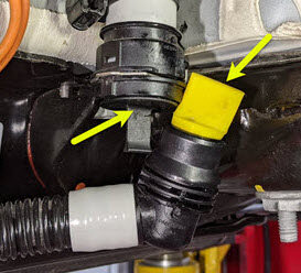
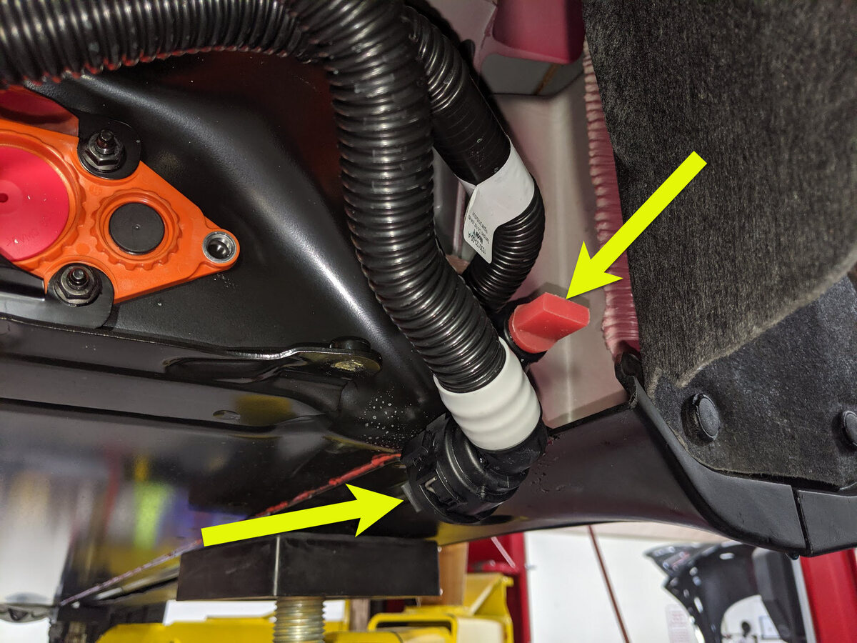
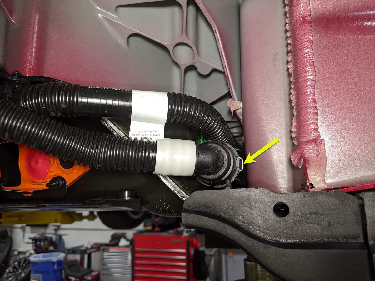
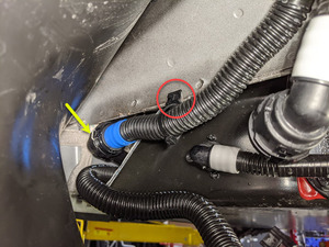
Disconnect rear PT supply hose at RH
side of vehicle and plug both hoses.
Remarque2x plugs, 1x spring clip, Coolant loss greater than 1 L will require vacuum fill.
-
Position coolant drain container
underneath LH front of HV battery.

-
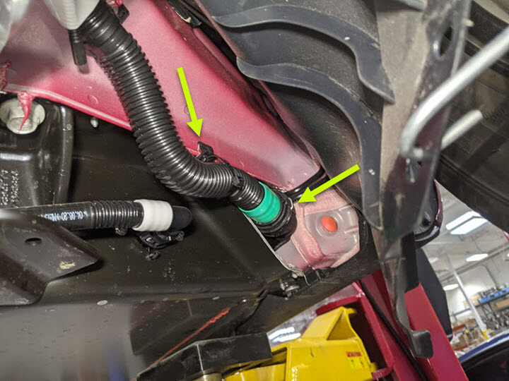
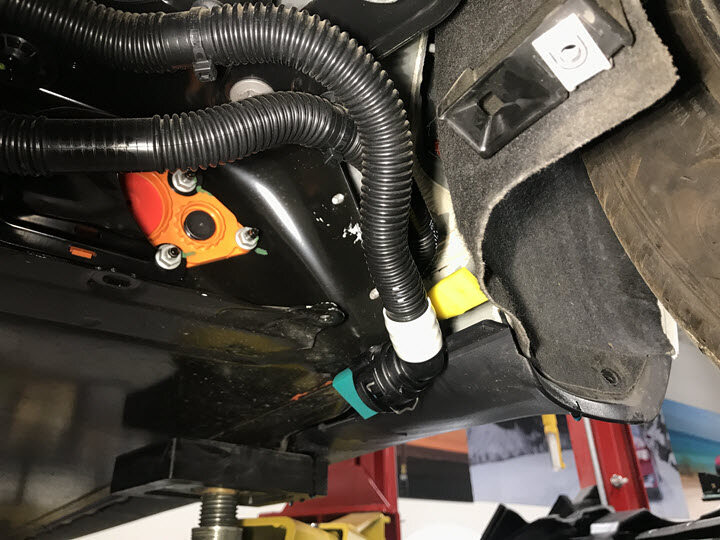
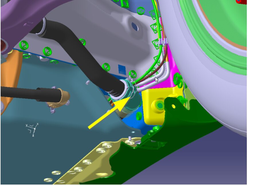
Disconnect HV battery return tube from
HV battery hose.
Remarque2x clips, 2x plugs, Located on LH front of HV battery, Install cap and plug to both ends, Coolant loss greater than 1 L will require vacuum fill.
-
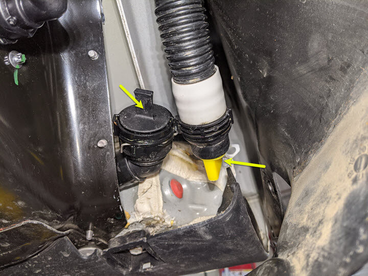
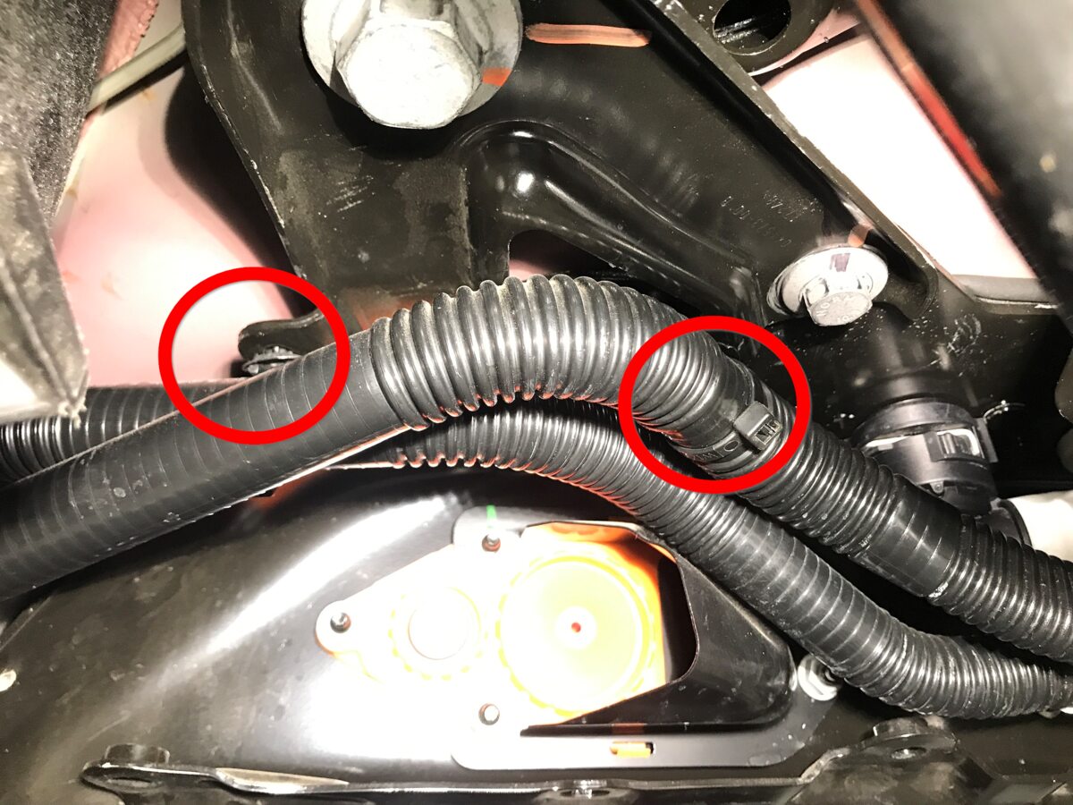
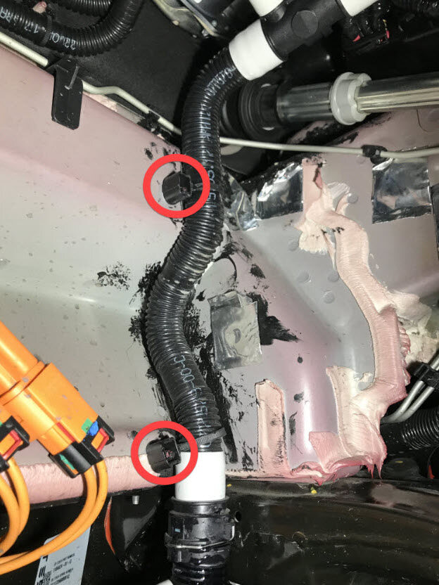
Release HV battery front manifold hose
from body.
Remarque2x clips.
-
Disconnect HV battery front manifold
hose and plug both hose ends.
Remarque1x spring clip, 2x plugs, Coolant loss greater than 1 L will require vacuum fill.
- Remove coolant drain container from underneath vehicle.
-
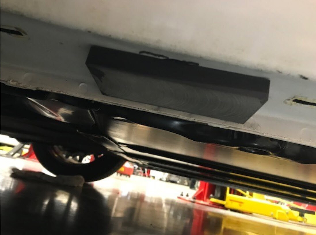
Remove mid aero shield.
Remarque13x bolts, 10mm, 5 Nm.

-
Support front portion of rear
subframe.

-
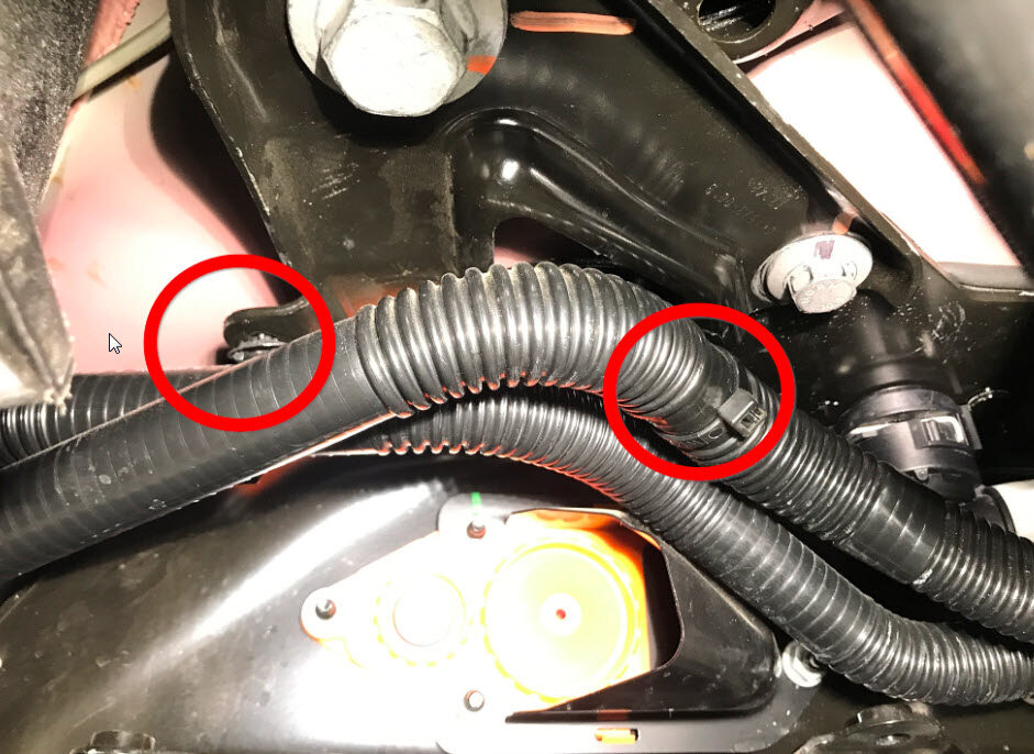
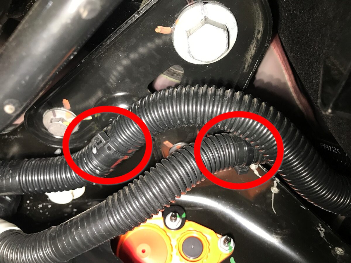
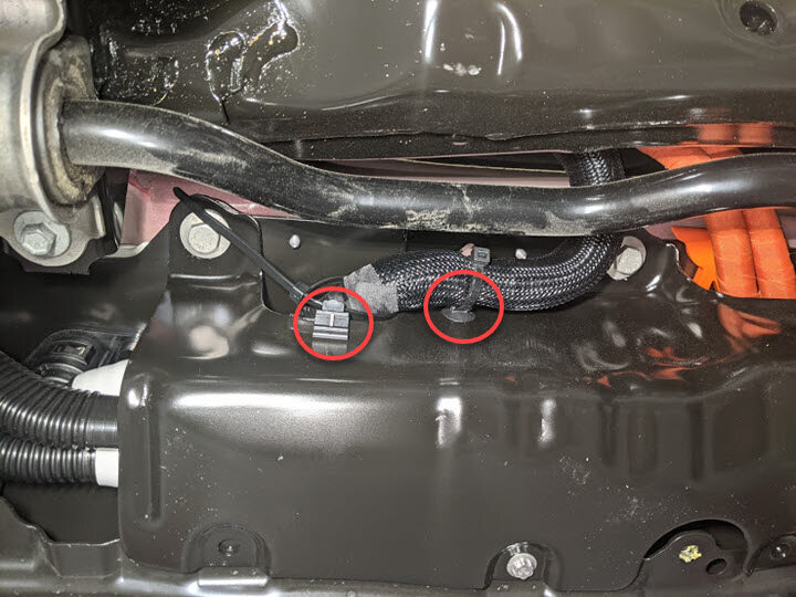
Release clips securing coolant hoses
to LH shear plate.
Remarque2x fir tree clips.
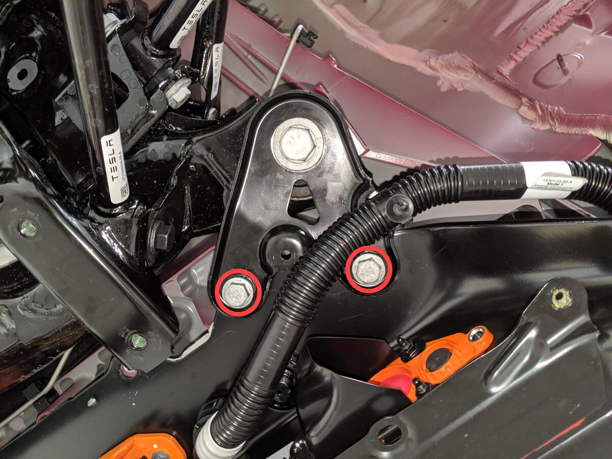
-
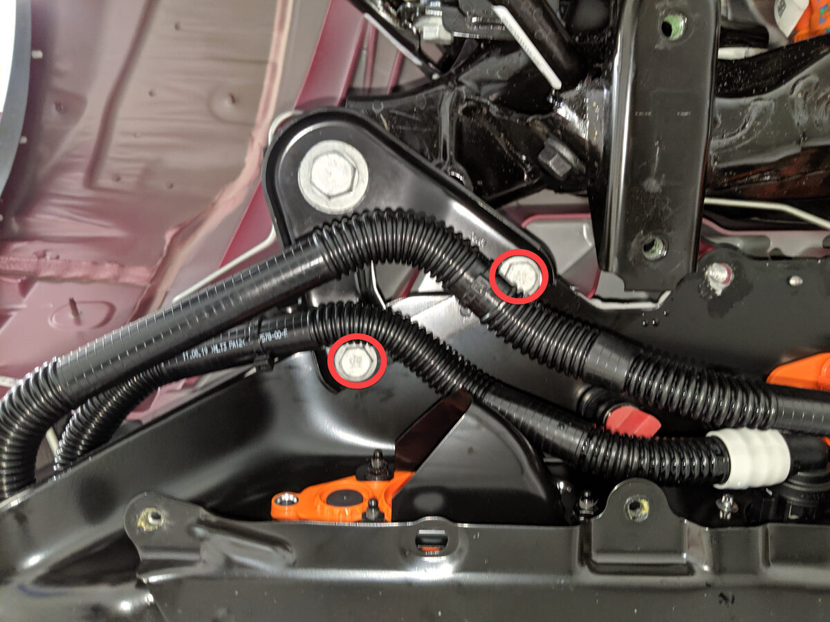
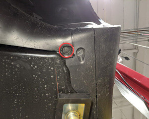
Remove smaller fasteners securing LH
shear plate.
Remarque2x bolts, 13mm, 35 Nm.
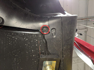
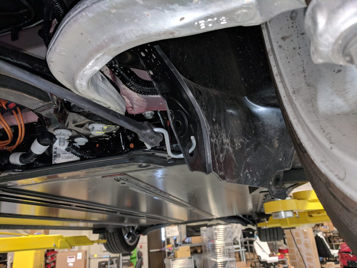
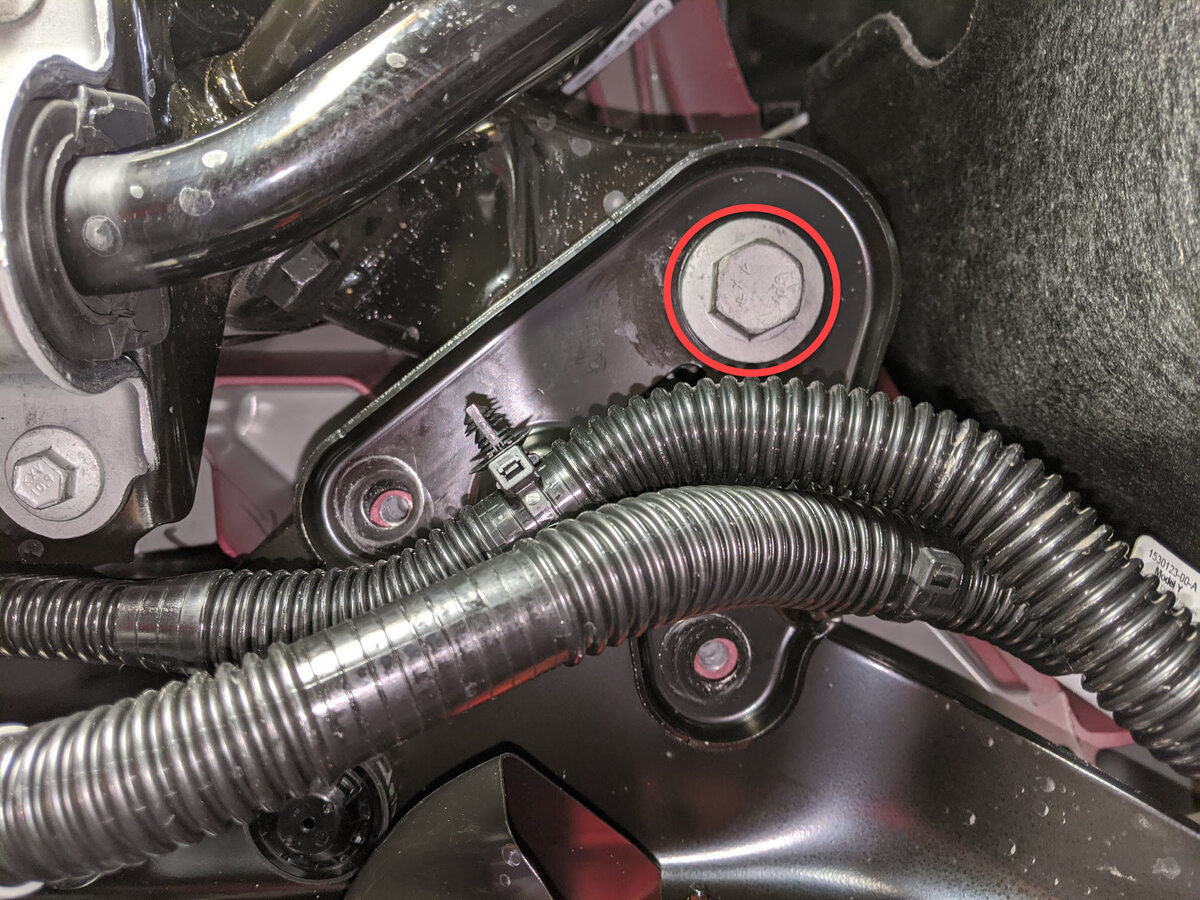
-
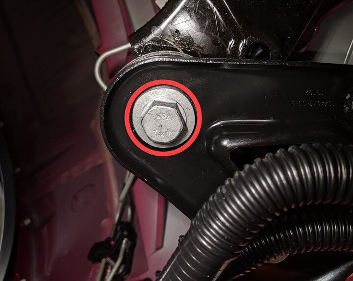
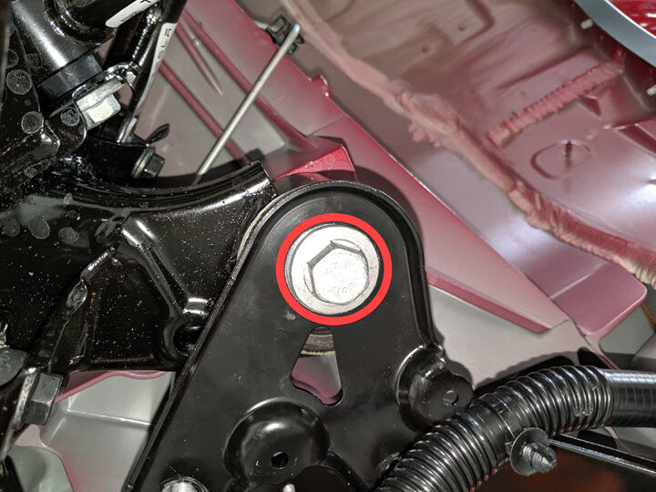
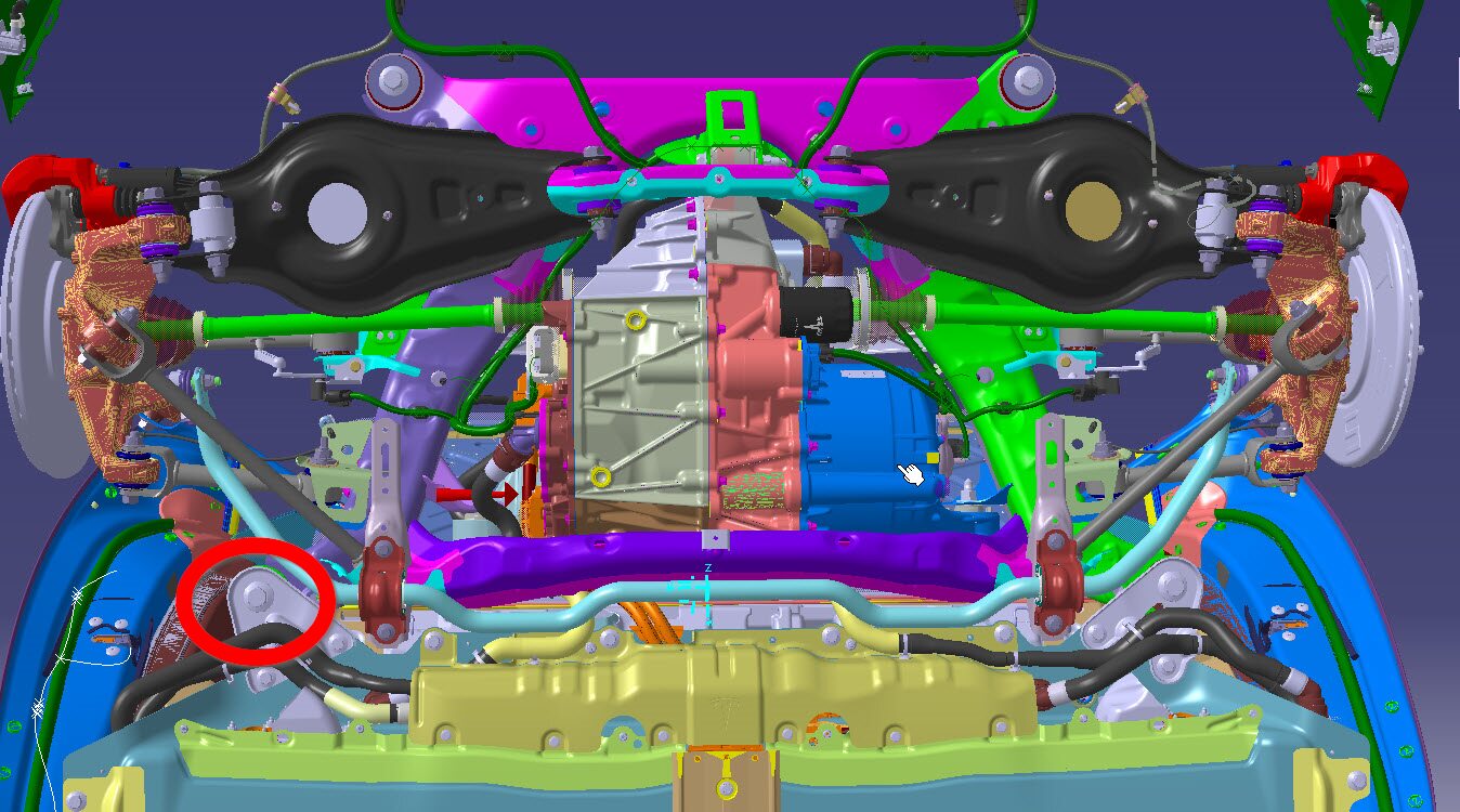
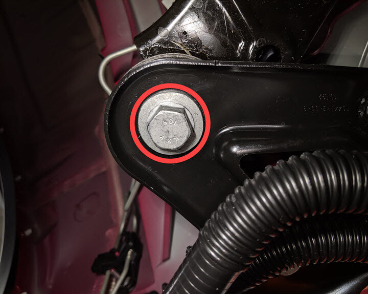
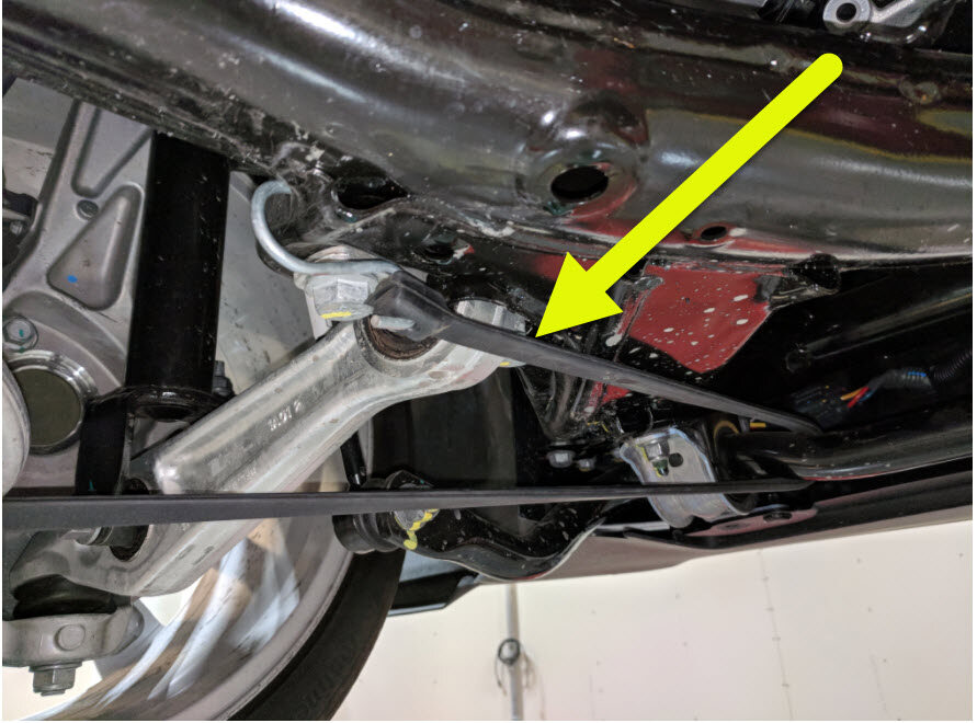
Remove large bolt securing LH shear
plate and subframe to body and remove shear plate.
Remarque1x bolt, 21mm, 130 Nm, Discard after removal.
-
Hand tighten bolt securing LH side of
subframe to body.
Remarque1x bolt, 21mm, 130 Nm.
-
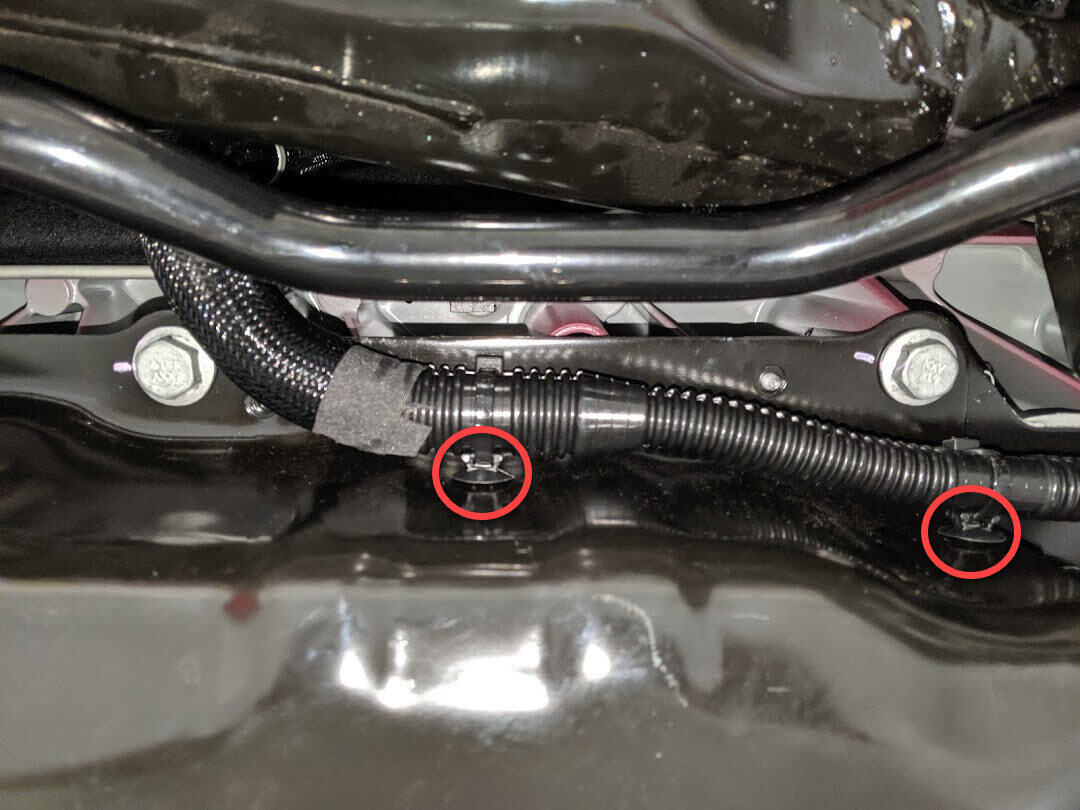
Release clips securing coolant hoses
to RH shear plate.
Remarque2x fir tree clips.
-
Remove smaller fasteners for RH shear
plate.
Remarque2x bolts, 13mm, 35 Nm.

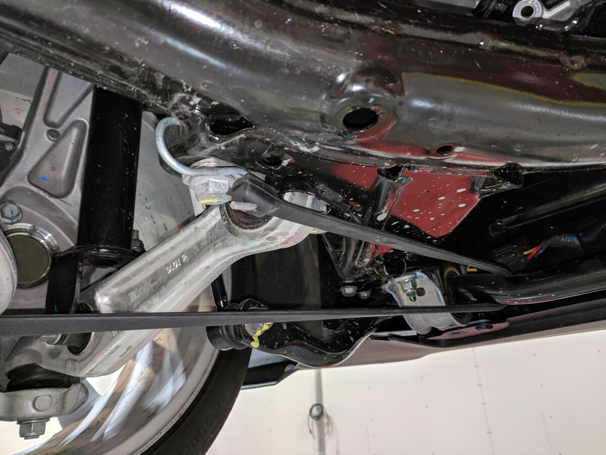
-
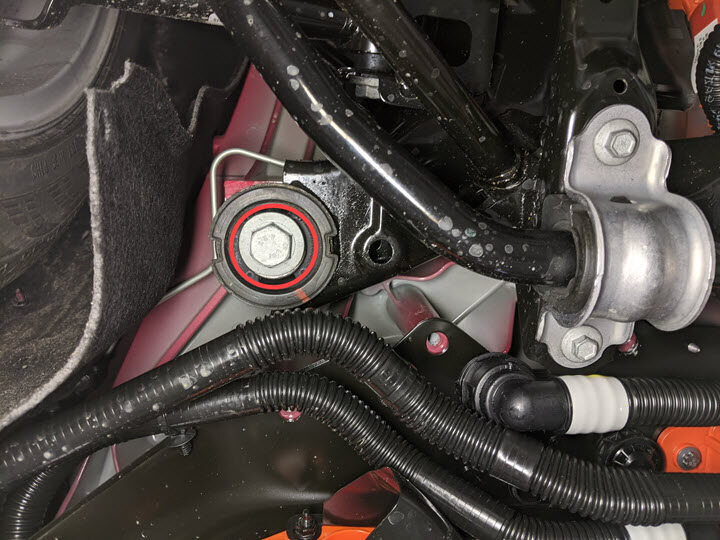
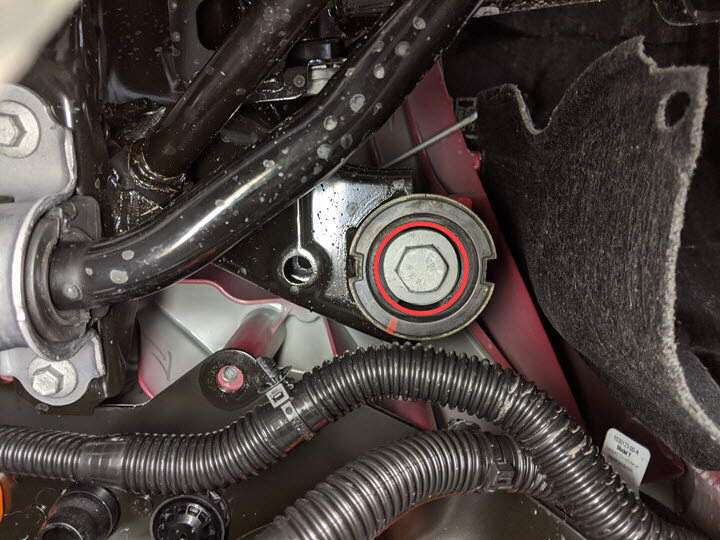
Remove large bolt securing RH shear
plate and subframe to body and remove shear plate.
Remarque1x bolt, 21mm, 130 Nm, Discard at later step.
-
Hand tighten bolt securing RH side of
subframe to body.
Remarque1x bolt, 21mm, 130 Nm.
-
Remove support stand from under
vehicle.

-
Release LH side hose clip from rear
battery skid plate enclosure.
Remarque2x clips, Clip quantity may vary on older vehicles.
-
Release RH side hose clips from rear
battery skid plate enclosure.
Remarque2x fir tree clips.
-
Remove lower bolts securing HV battery
rear skid plate enclosure .
Remarque2x bolts, EP10, 13 Nm, Older vins may be equipped with additional fastener count.

-
Remove upper nut securing HV battery
rear skid plate enclosure .
Remarque1x nut, 10mm, 13 Nm, Fastener count may vary on older built vehicles.
-
Remove upper bolts securing HV battery
rear skid plate enclosure .
Remarque4x bolts, 13mm, 35 Nm.
-
Remove HV battery rear skid plate
enclosure .
- Position coolant drain container underneath LH rear of HV battery.
-
Disconnect RDU inverter inlet tube
from LH rear of HV battery.
Remarque1x spring clip, 2x plugs, Plug HV battery and hose, Coolant loss greater than 1 L will require vacuum fill.
-
Position coolant drain container
underneath RH rear of vehicle.
-
Disconnect RDU outlet hose from PT
return tube and plug both hose ends.
Remarque1x spring clip, 2x plugs, Lower hose located at RH rear of HV battery, Use shop towel to clean any residue coolant if necessary, Coolant loss greater than 1 L will require vacuum fill.

- Remove coolant drain container from underneath vehicle.
-
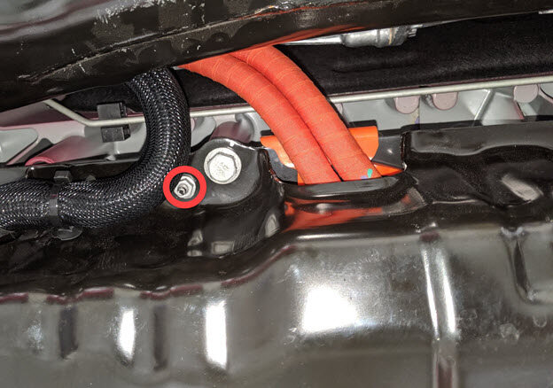
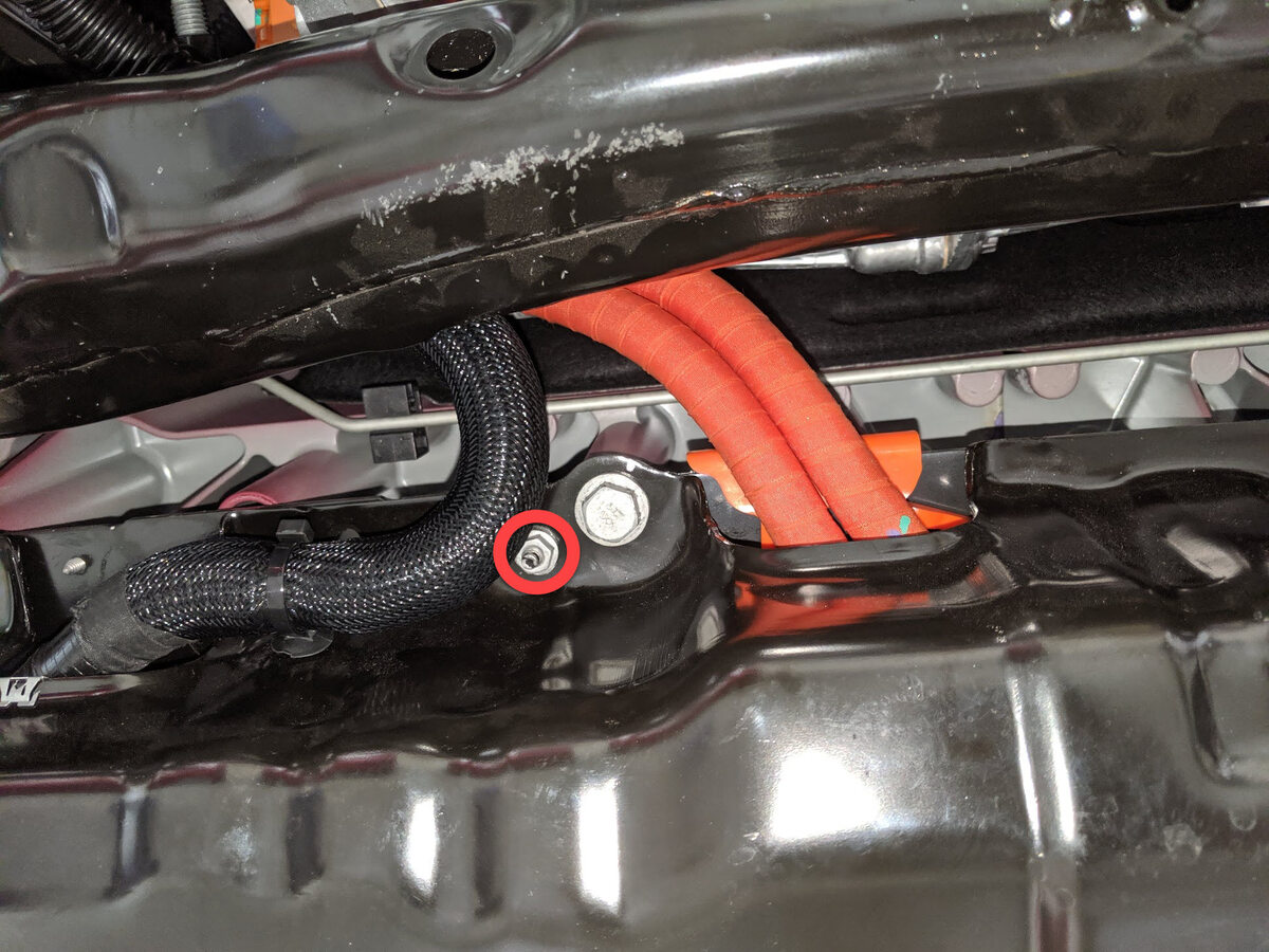
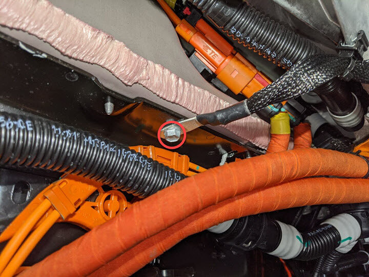
Remove nut securing RDU HV cable
bracket to HV battery.
Remarque1x nut, 10mm, 10 Nm, Number of fasteners may vary.
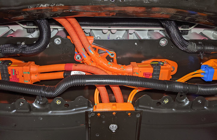
-
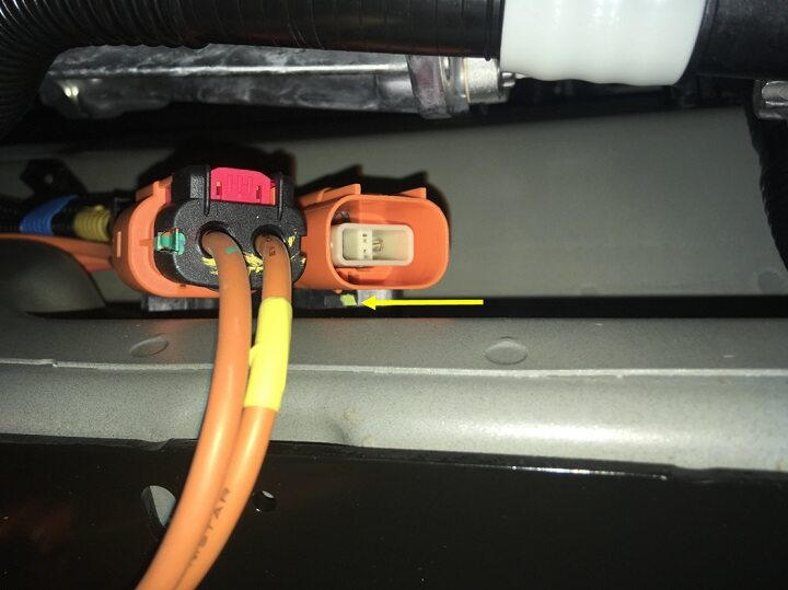
Disconnect RDU HV cable from HV
battery.
Remarque1x connector, Release locking tab and rotate the release lever up to disengage the connector, Do not force the release lever up, Ensure the alignment tabs on the RDU header are not damaged.
-
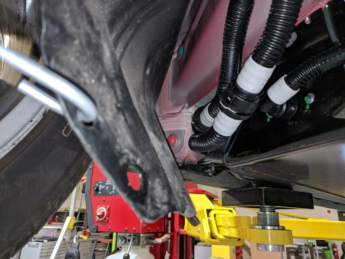
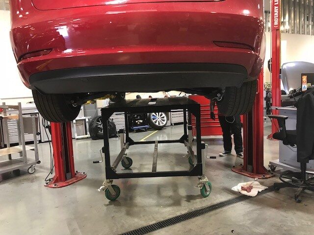
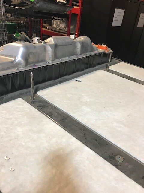
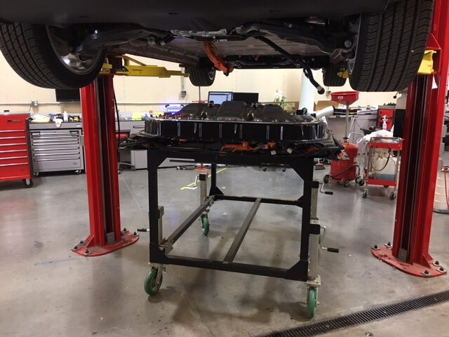
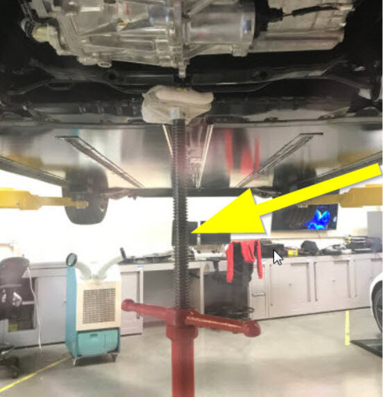
Place HV battery table into position
and lower vehicle to support HV battery.
RemarqueRecommend assistance, Line up table so center 4 bolts are accessible through opening in table, Adjust final battery table position using adjustable caster jacks on table.
-
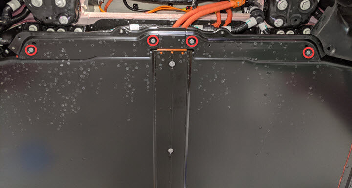
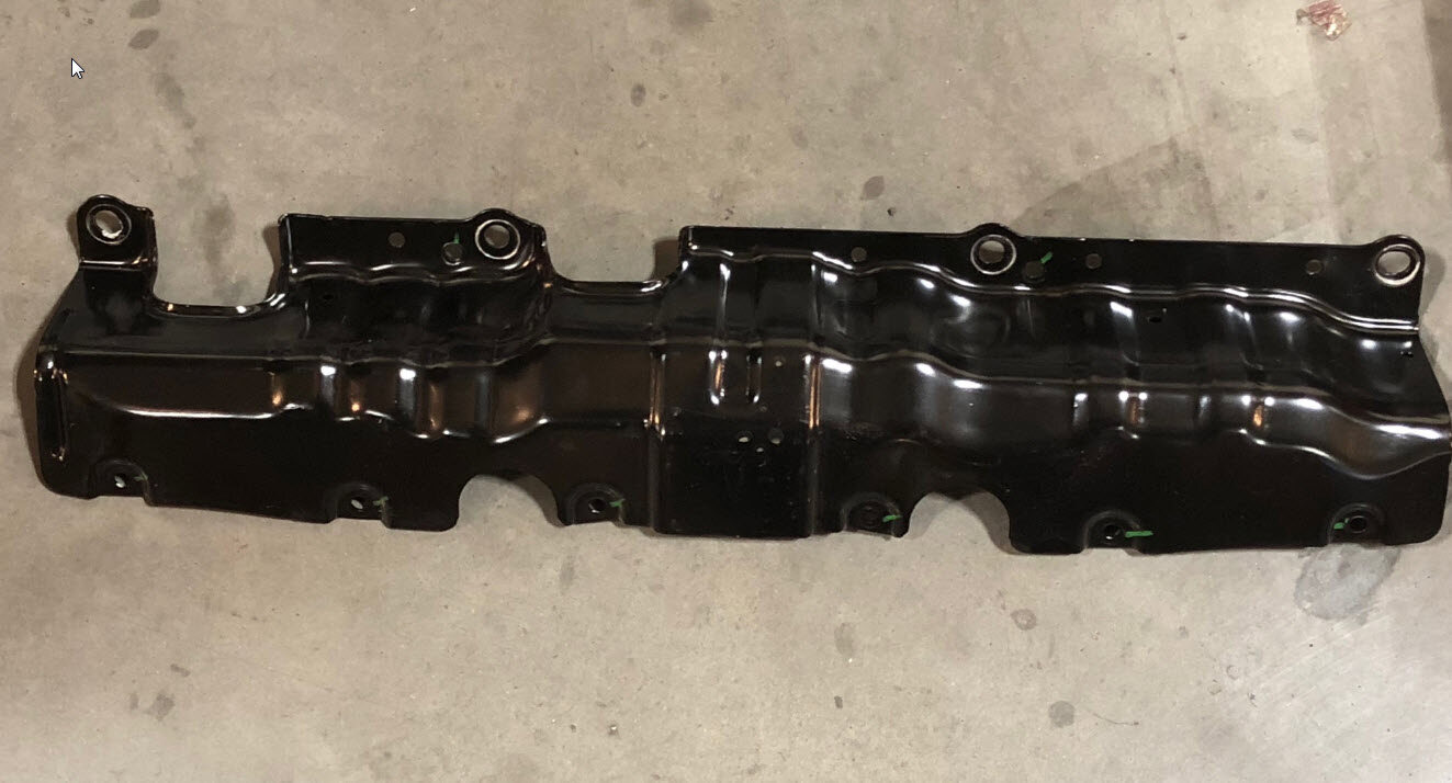
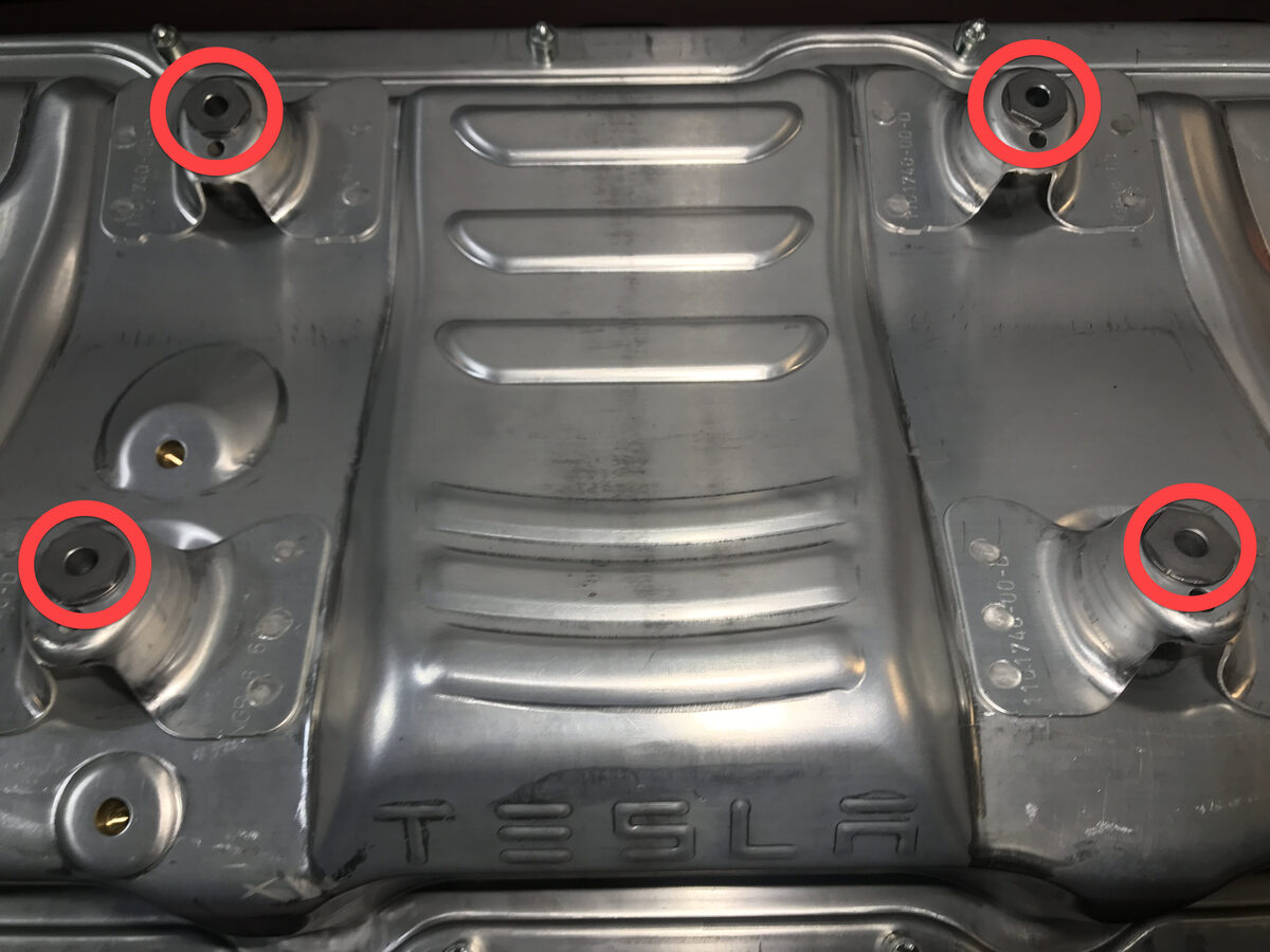
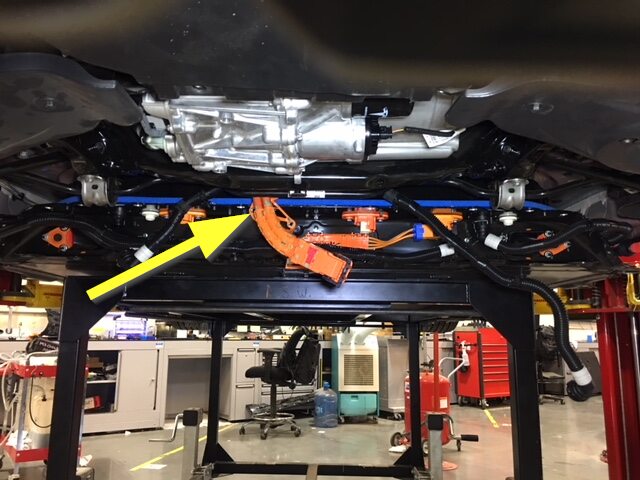
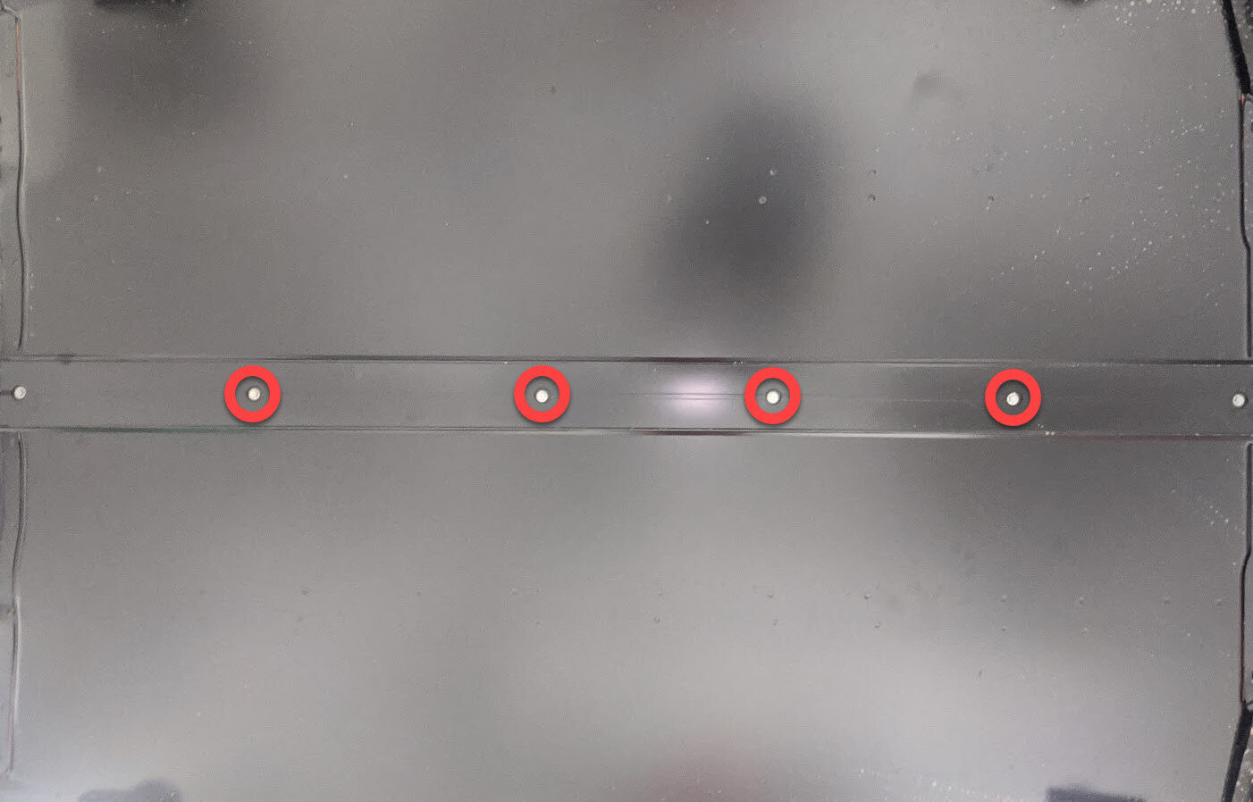
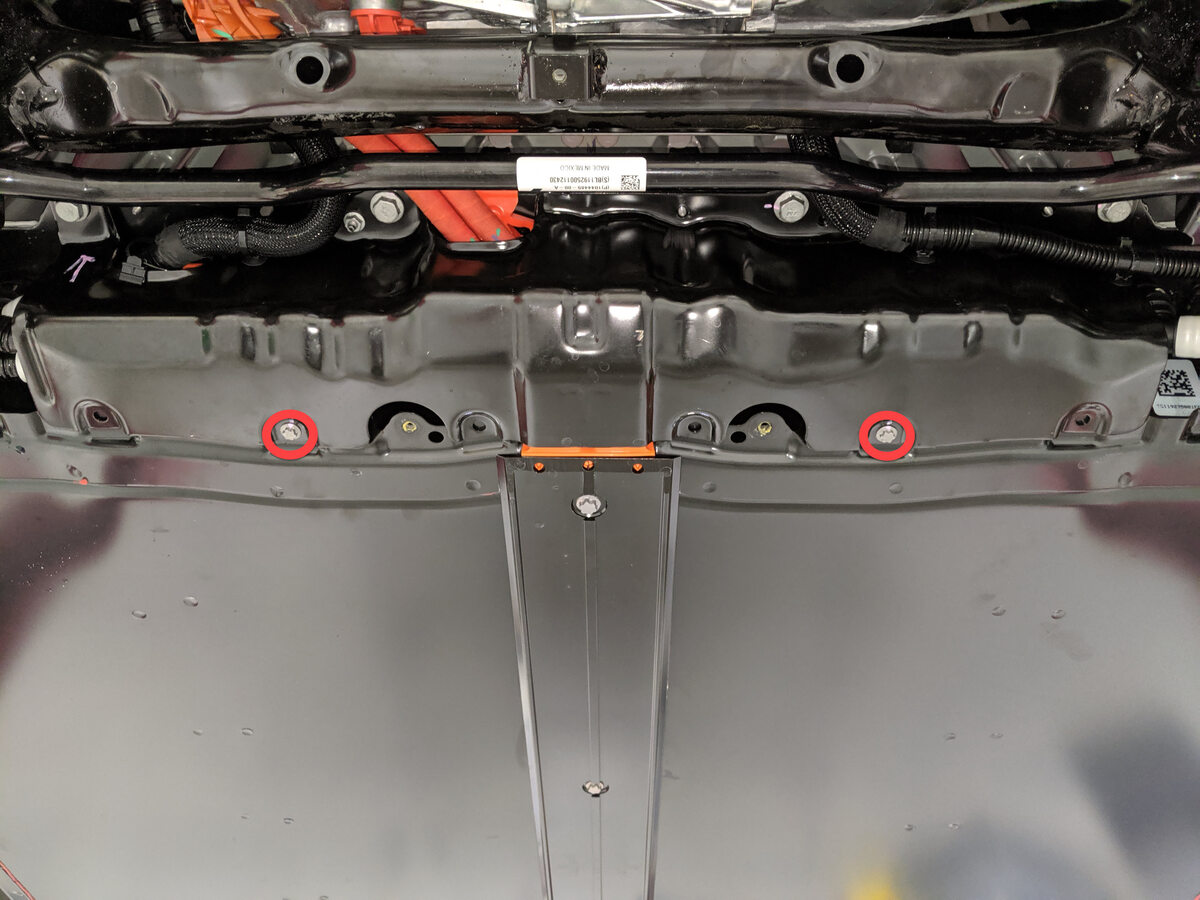
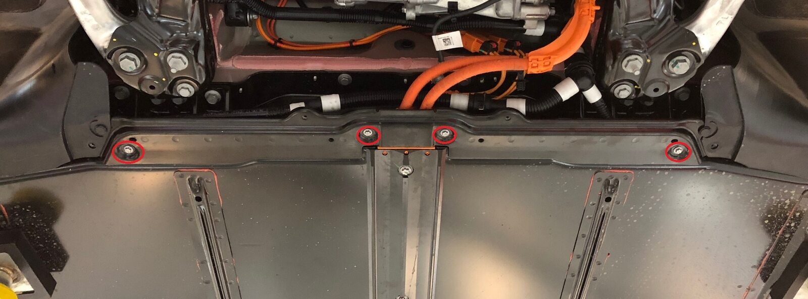
Remove central bolts securing HV
battery center ski cover.
Remarque4x bolts, EP14, 34 Nm.

-
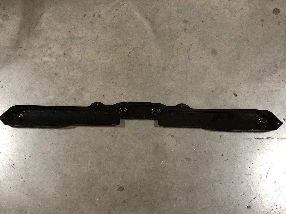
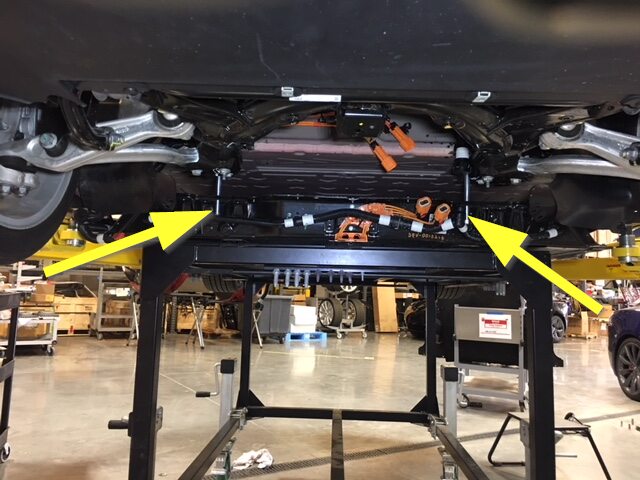
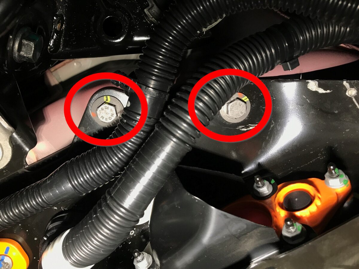
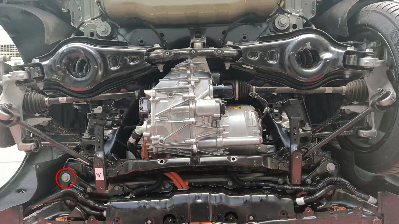
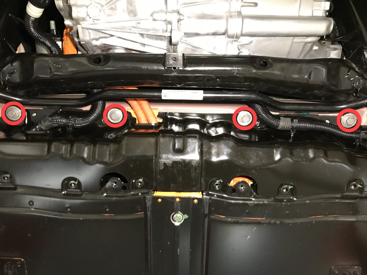
Remove bolts securing LH front support
bracket to vehicle.
Remarque4x bolts, 16mm, 110 Nm.

-
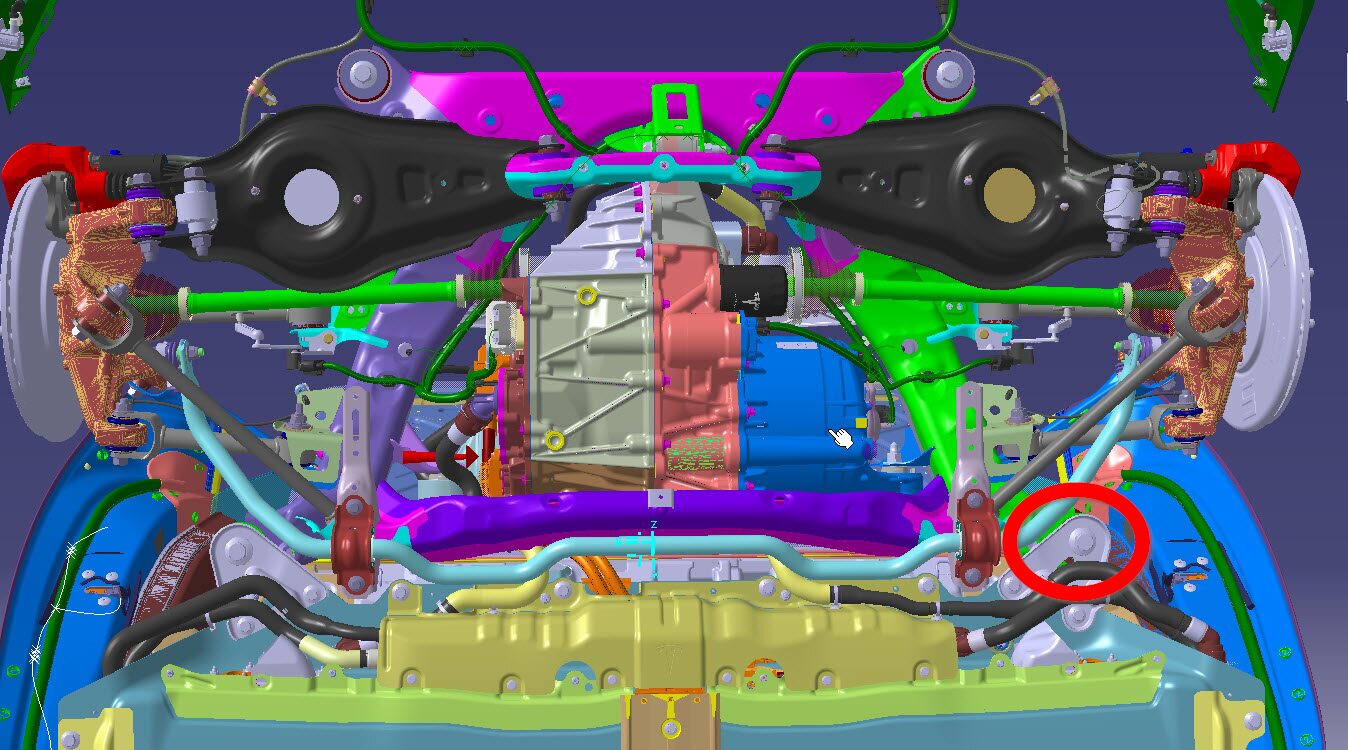
Remove bolts securing RH front support
bracket to vehicle.
Remarque4x bolts, 16mm, 110 Nm.

-
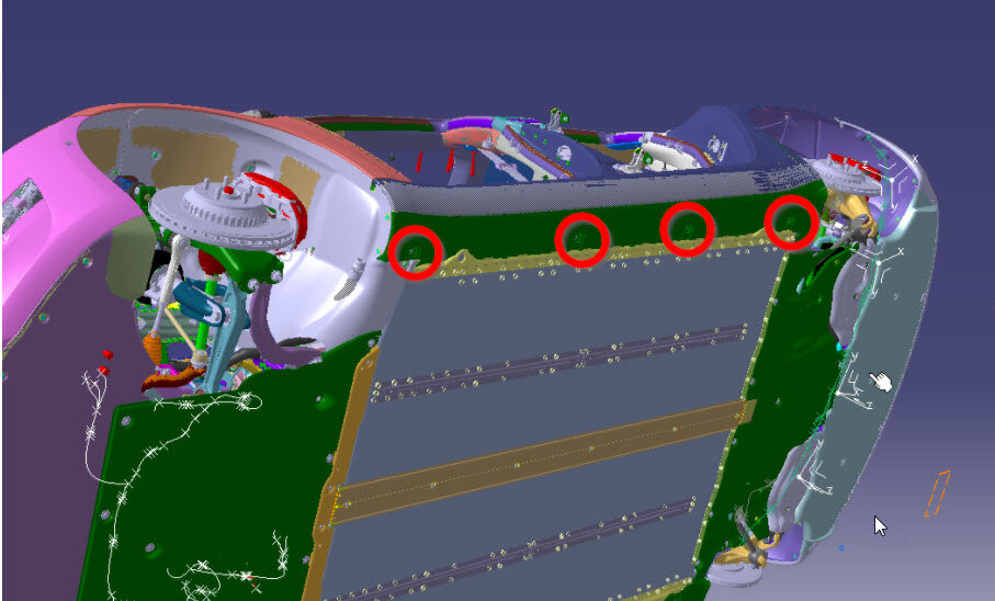
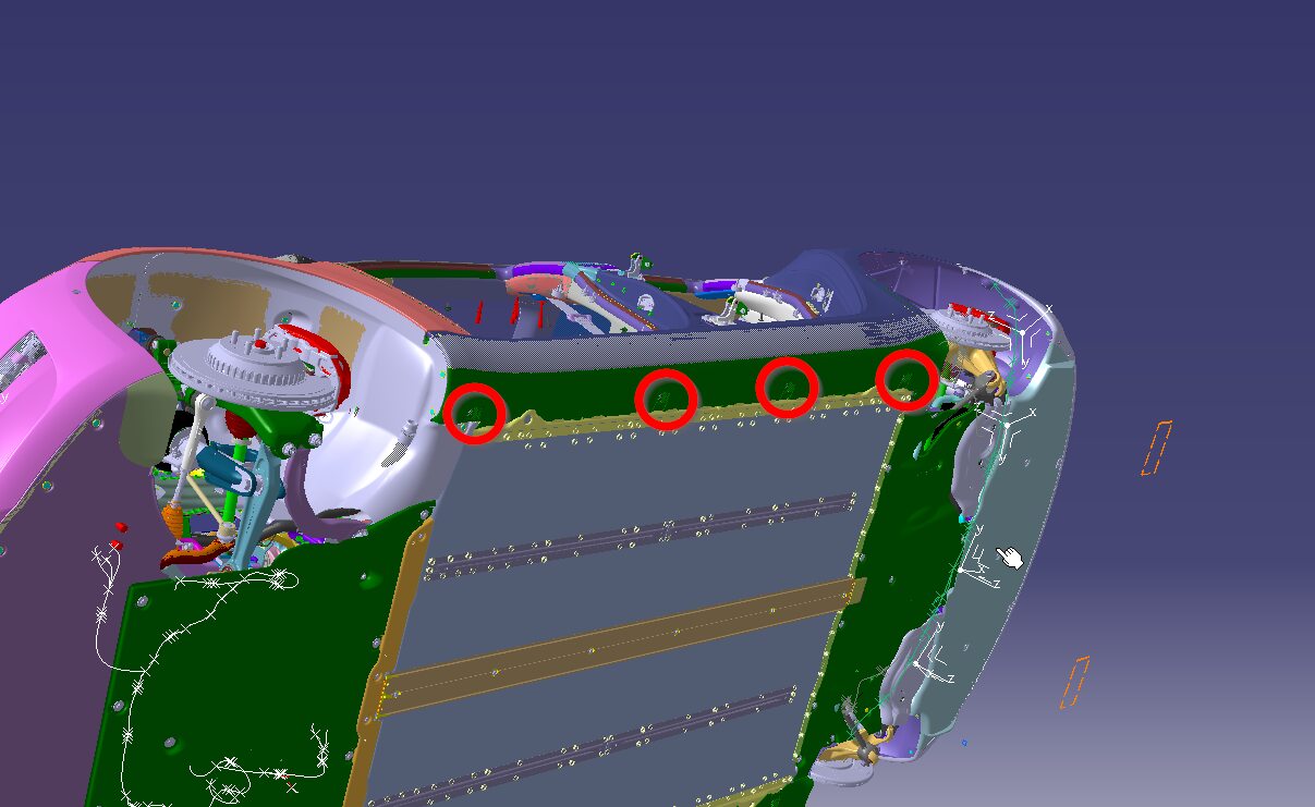
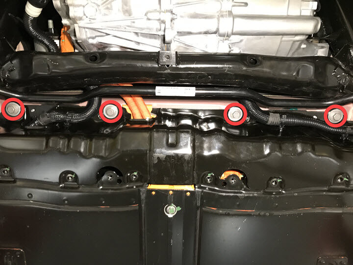
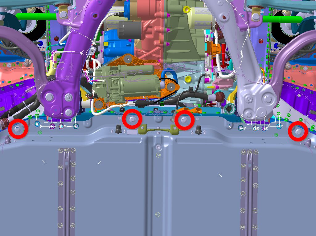
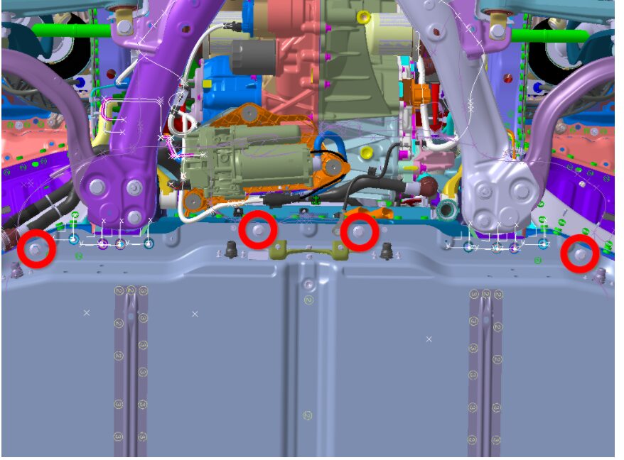
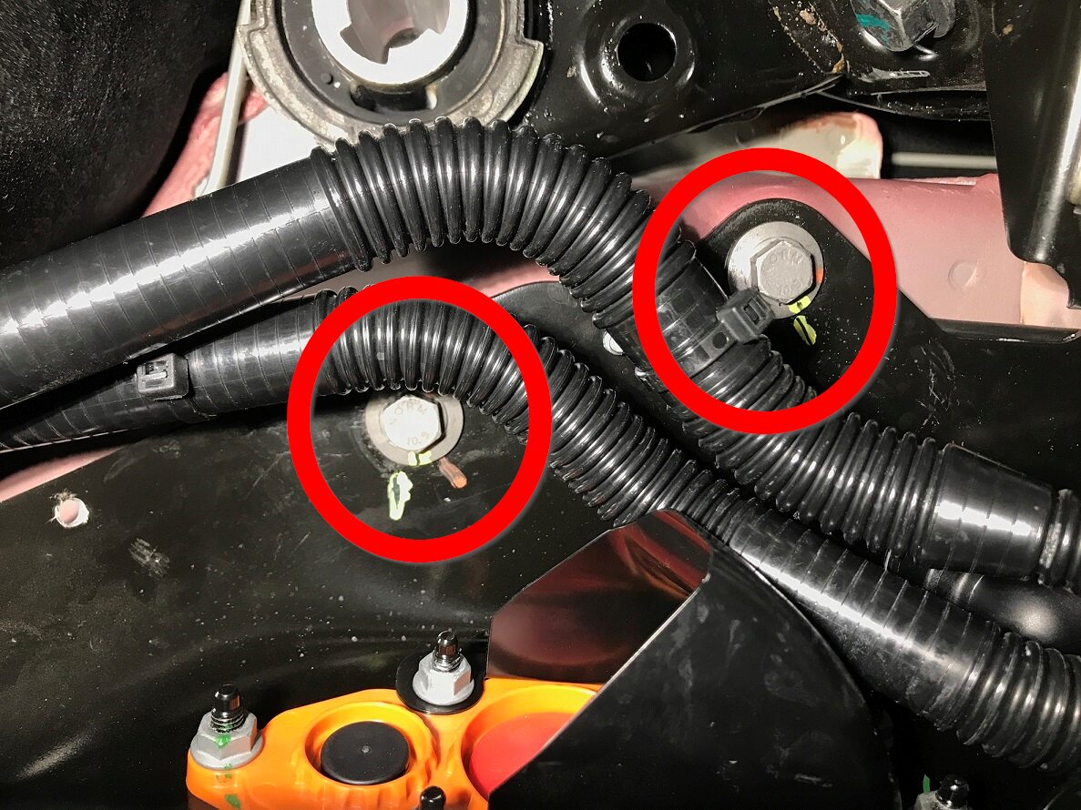
Remove front bolts securing HV battery
to vehicle.
Remarque4x bolts, 13mm, 35 Nm, The number of fasteners on newer vehicles may vary.
-
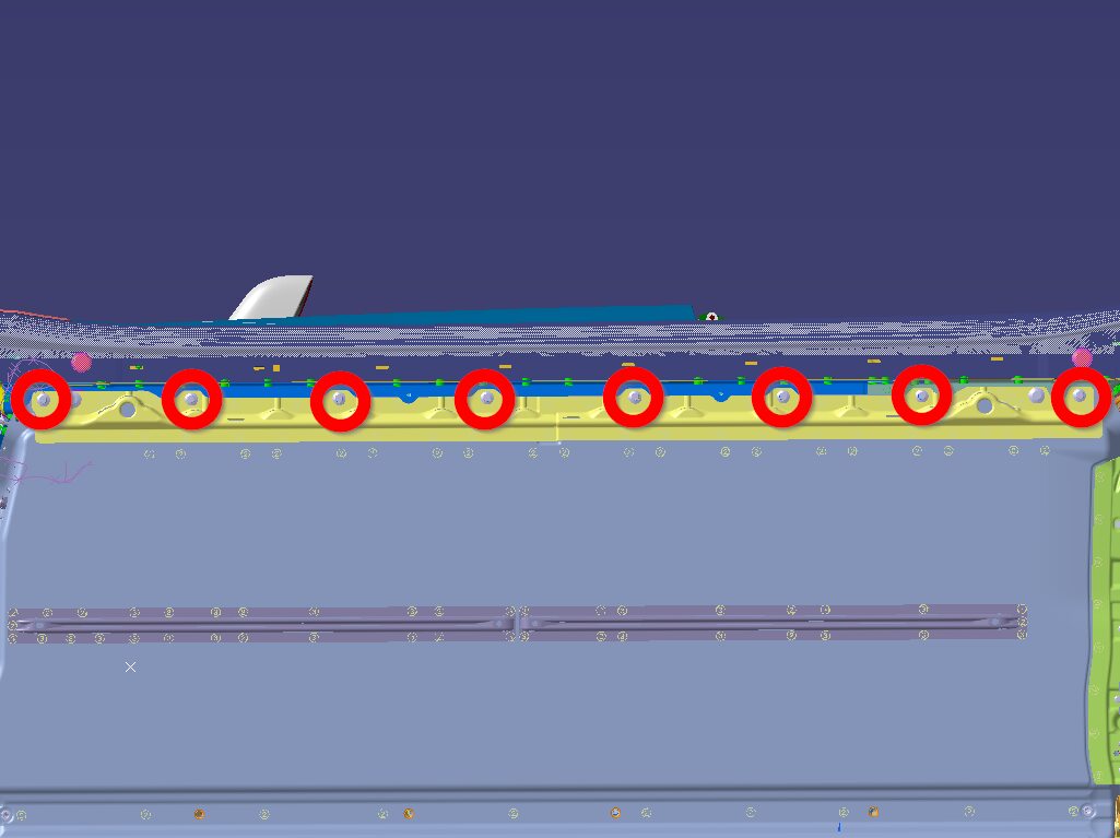
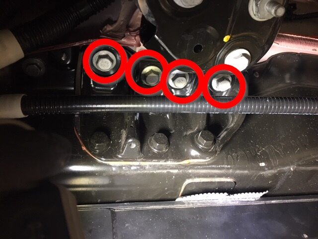
Remove LH bolts securing HV battery to
vehicle.
Remarque8x bolts, 13mm, 35 Nm.
-
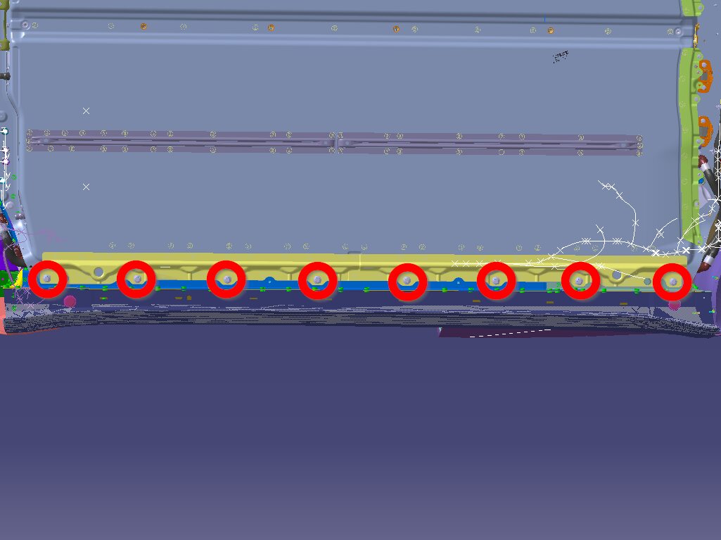
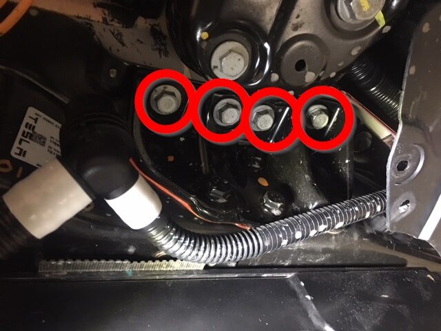
Remove RH bolts securing HV battery to
vehicle.
Remarque8x bolts, 13mm, 35 Nm.
-
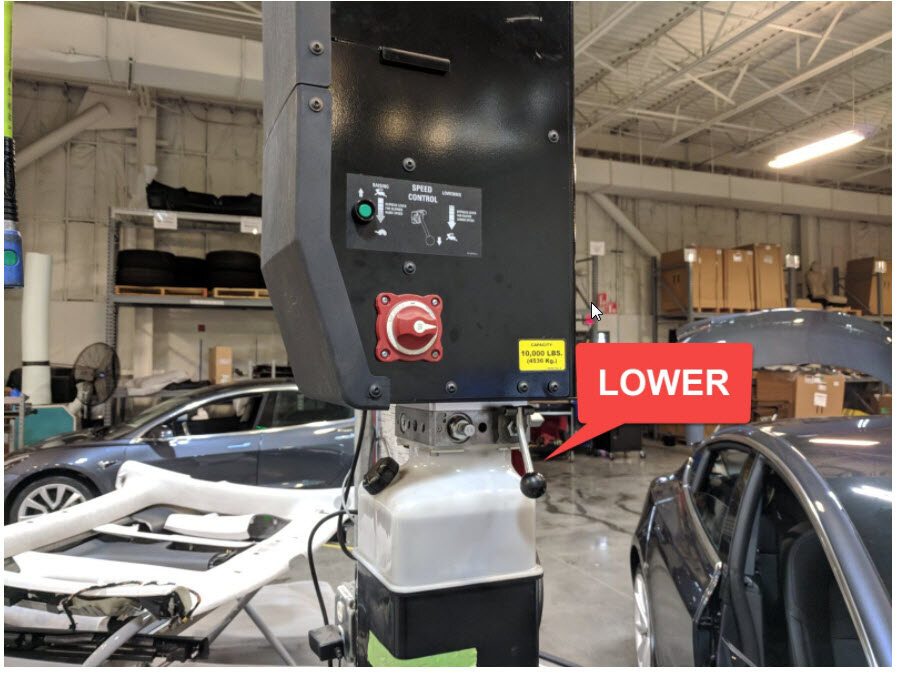
Raise vehicle free of HV battery.
RemarqueRecommend assistance.

-
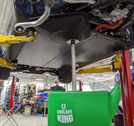
Remove battery from under
vehicle.
RemarqueRecommend assistance.
Installer
-
Spin Flexitol adjustable elements down
on the ancillary bay cover.
Remarque4x nuts, Reverse thread.
-
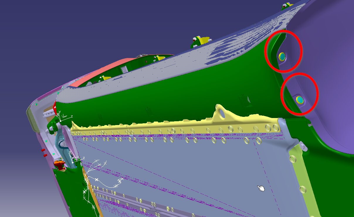
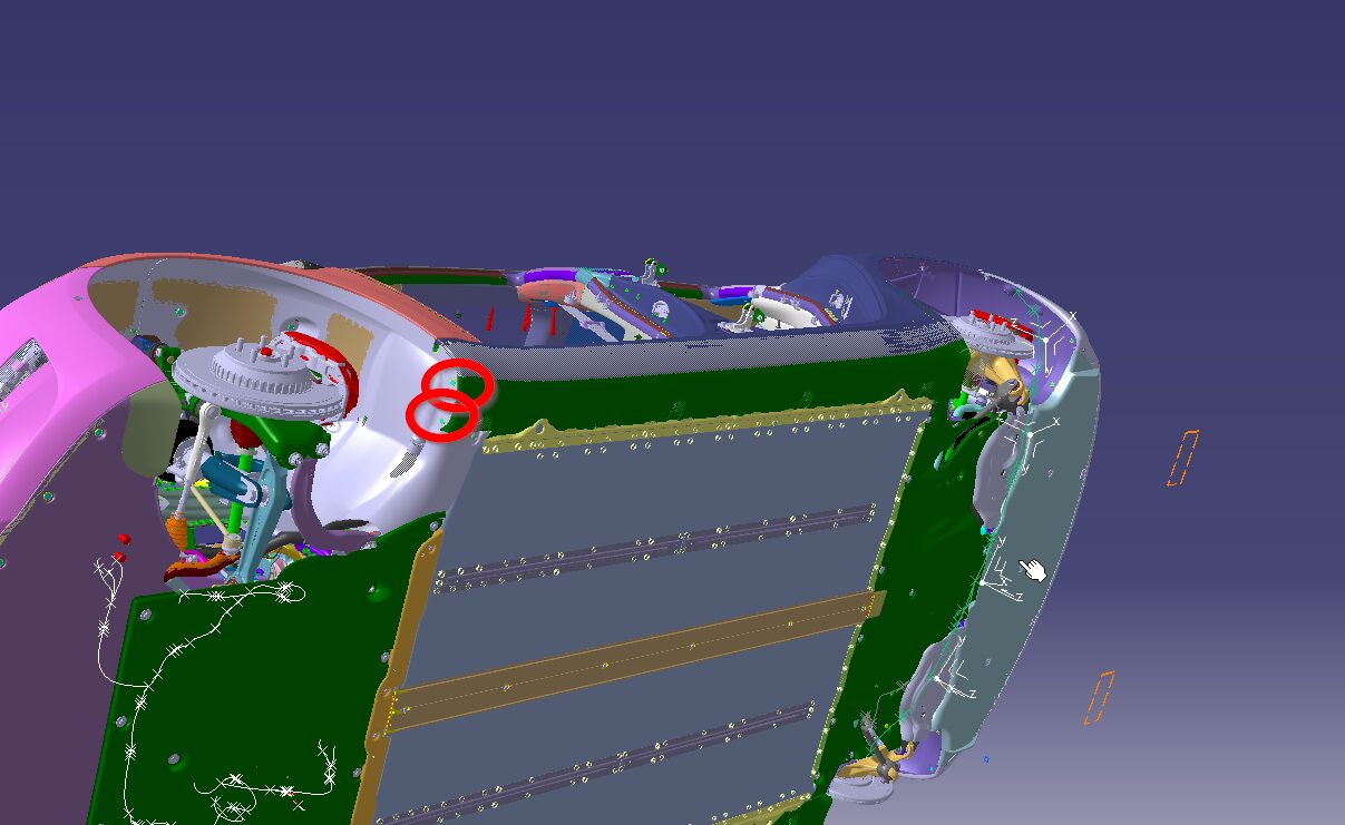
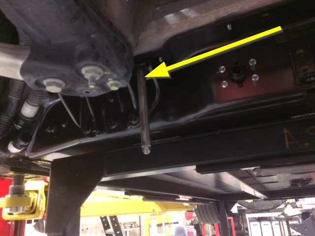
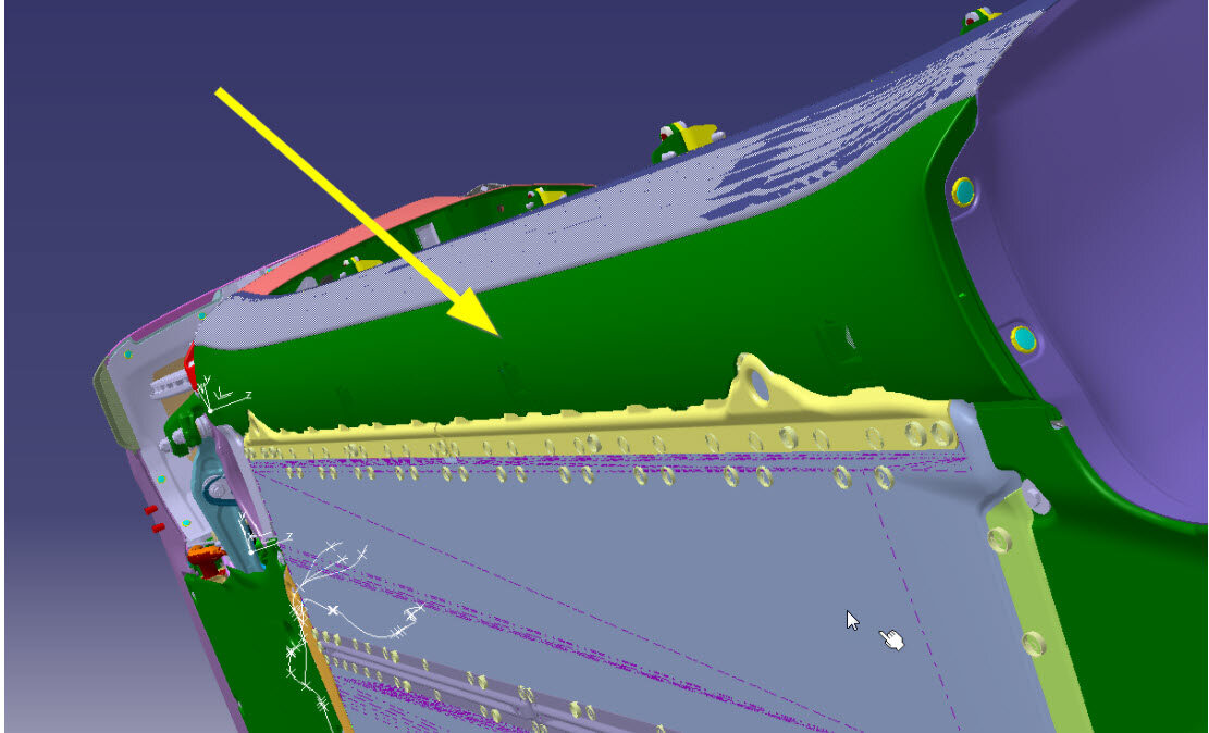
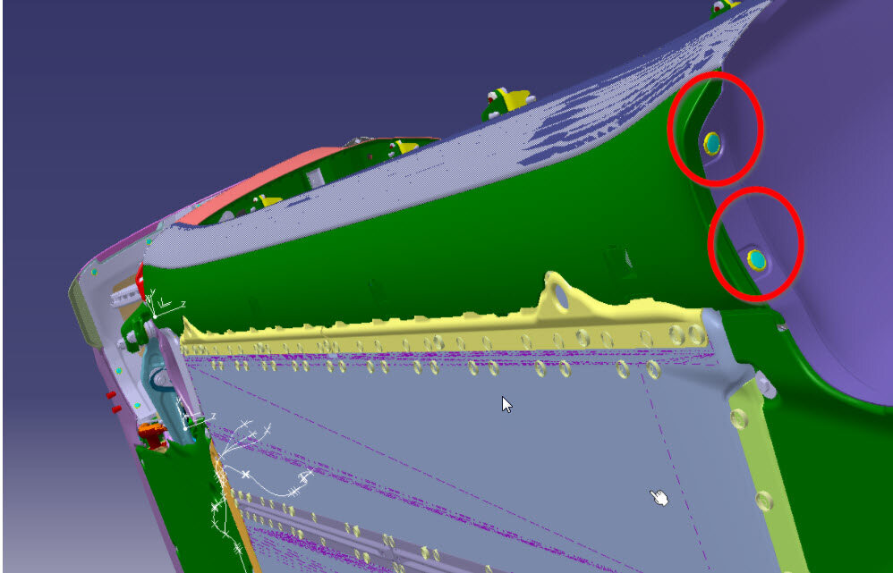
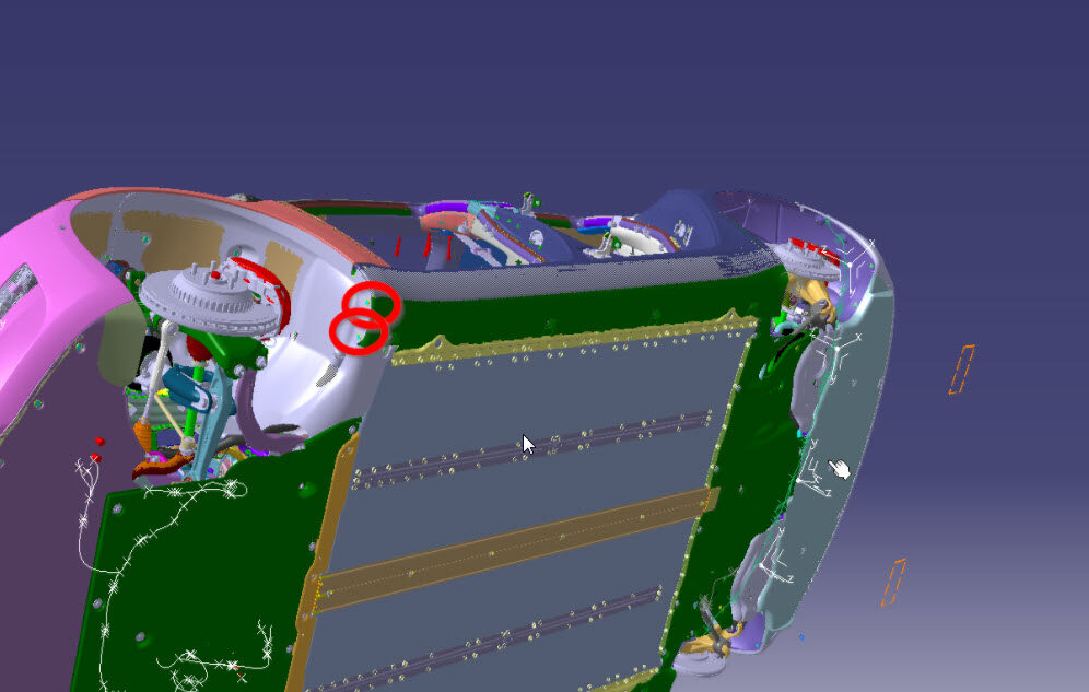
Install HV battery alignment
rods.
Remarque2x rods, To body at front of vehicle, 2x rods, To battery near ancillary bay.

-
Position HV battery under
vehicle.
RemarqueRecommend assistance.
-
Lower vehicle onto HV battery and
align holes.
RemarqueRecommend assistance, Use alignment rods, Be sure coolant hoses do not get caught on alignment rods, Caution not to damage HV cable, Do not fully lower vehicle onto battery (this will help with installing battery bolts).

-
Set RH bolts securing HV battery to
vehicle with cordless impact.
Remarque8x bolts, 13mm, 35 Nm, Ensure smooth thread engagement and bolts are not cross threaded into casting, Flush down bolts, Do not over tighten bolts, Fully torque at later step.

-
Set LH bolts securing HV battery to
vehicle with cordless impact.
Remarque8x bolts, 13mm, 35 Nm, 8x bolts, 13mm, 35 Nm, Ensure smooth thread engagement and bolts are not cross threaded into casting, Flush down bolts, Do not over tighten bolts, Fully torque at later step.

-
Install front bolts securing HV
battery to vehicle hand tight.
Remarque4x bolts, 13mm, 35 Nm, The number of fasteners on newer vehicles may vary, Reinstall fastener unless the body is patched or no hole exists, Patch the body if HV battery doesn't have these holes.
-
Remove HV battery alignment rods.
Remarque2x rods, To body at front of vehicle, 2x rods, To battery near ancillary bay.
-
Set bolts securing RH front support
bracket to vehicle with cordless impact.
Remarque4x bolts, 16mm, 110 Nm, 8x bolts, 13mm, 35 Nm, Ensure smooth thread engagement and bolts are not cross threaded into casting, Flush down bolts, Do not over tighten bolts, Fully torque at later step.
-
Set bolts securing LH front support
bracket to vehicle with cordless impact.
Remarque4x bolts, 16mm, 110 Nm, 8x bolts, 13mm, 35 Nm, Ensure smooth thread engagement and bolts are not cross threaded into casting, Flush down bolts, Do not over tighten bolts, Fully torque at later step.
-
Install bolts securing HV battery to
body at LH shear plate area hand tight.
Remarque2x bolts, 13mm, 35 Nm, Torque at later step.
-
Install bolts securing HV battery to
body at RH shear plate area hand tight.
Remarque2x bolts, 13mm, 35 Nm, Torque at later step.
-
Open LH rear door.
RemarqueUse caution while working around this area not to damage any components.
-
Set LH rear HV battery interior bolt
with cordless impact.
Remarque1x bolt, 16mm, 66 Nm, Lift up carpet for access, Ensure smooth thread engagement and bolts are not cross threaded into pack, Flush down bolts, Do not over tighten bolts, Fully torque at later step.

-
Close LH rear door.
RemarqueDo not latch.
-
Open LH front door.
RemarqueUse caution while working around this area not to damage any components.
-
Set LH front footwell HV battery bolts
with cordless impact .
Remarque2x bolts, EP20, 136 Nm, Ensure smooth thread engagement and bolts are not cross threaded into pack, Flush down bolts, Do not over tighten bolts, Fully torque at later step.
-
Close LH front door.
RemarqueDo not latch.
-
Open RH rear door.
RemarqueUse caution while working around this area not to damage any components.
-
Set RH rear HV battery interior bolt
with cordless impact.
Remarque1x bolt, 16mm, 66 Nm, Lift up carpet for access, Ensure smooth thread engagement and bolts are not cross threaded into pack, Flush down bolts, Do not over tighten bolts, Fully torque at later step.
-
Close RH rear door.
RemarqueDo not latch.
-
Open RH front door.
RemarqueUse caution while working around this area not to damage any components.
-
Set LH front footwell HV battery bolts
with cordless impact .
Remarque2x bolts, EP20, 136 Nm, Ensure smooth thread engagement and bolts are not cross threaded into pack, Flush down bolts, Do not over tighten bolts, Fully torque at later step.

-
Close RH front door.
RemarqueDo not latch.
-
Lower vehicle onto pack
completely.
RemarqueRecommend assistance.
-
Torque RH bolts securing HV battery to
vehicle.
Remarque8x bolts, 13mm, 35 Nm.
-
Torque LH bolts securing HV battery to
vehicle.
Remarque8x bolts, 13mm, 35 Nm.
-
Torque front bolts securing HV battery
to vehicle.
Remarque4x bolts, 13mm, 35 Nm, The number of fasteners on newer vehicles may vary, If joint is found loose, note the VIN, joint location, take pictures and escalate via toolbox session.

-
Torque bolts securing RH front support
bracket to vehicle.
Remarque4x bolts, 16mm, 110 Nm.

-
Torque bolts securing LH front support
bracket to vehicle.
Remarque4x bolts, 16mm, 110 Nm.

-
Torque central bolts securing HV
battery center ski cover.
Remarque4x bolts, EP14, 34 Nm.
-
Raise vehicle and lower onto locks,
then remove battery table from under vehicle.
RemarqueRecommend assistance, Set vehicle to comfortable working height, Make sure there's an audible click of the locks on both sides before lowering, otherwise vehicle may tilt to the side.

-
Support front portion of rear
subframe.
-
Remove smaller fasteners for LH shear
plate.
Remarque2x bolt, 13mm, 35 Nm.

-
Remove smaller fasteners for RH shear
plate.
Remarque2x bolt, 13mm, 35 Nm.

-
Install LH front bolt and shear plate
to rear subframe hand tight.
Remarque1x bolt, 21mm, 130 Nm, Install new bolt, Torque at later step.
-
Install bolts securing LH shear plate
to HV battery hand tight.
Remarque2x bolts, 13mm, 35 Nm.

-
Install RH front bolt and shear plate
to rear subframe hand tight.
Remarque1x bolt, 21mm, 130 Nm, Install new bolt, Torque at later step.
-
Install bolts securing RH shear plate
to HV battery hand tight.
Remarque2x bolts, 13mm, 35 Nm.
-
Torque bolts securing shear plates to
vehicle.
Remarque4x bolts, 13mm, 35 Nm.


-
Torque bolt securing subframe and LH
shear plate to body.
Remarque1x front bolt, 21mm, 130 Nm, Mark bolt after torque.

-
Torque bolt securing subframe and RH
shear plate to body.
Remarque1x front bolt, 21mm, 130 Nm, Mark bolt after torque.
- Remove support stand from under vehicle.
-
Install clips securing coolant hoses
to RH shear plate.
Remarque2x fir tree clips.

-
Install clips securing coolant hoses
to LH shear plate.
Remarque2x fir tree clips.
-
Connect RDU HV cable to HV
battery.
Remarque1x connector, Make sure the connector lock is 90 degrees from the connector before beginning to secure the connector, Use one hand to support the connector while other latching locking tab. Once installed, verify that the latch is not damaged and fully secured in the latched position.
-
Install nut securing RDU HV cable
bracket to HV battery.
Remarque1x nut, 10mm, 10 Nm, Number of fasteners may vary.

-
Remove hose plugs and connect RDU
outlet hose to PT return tube.
Remarque1x spring clip, 2x plugs, Perform push-pull-push test to make sure hose is fully engaged, Use shop towel to clean any coolant residue if necessary, Loss of coolant greater than 1L requires coolant vacuum fill.
-
Remove plugs and connect RDU inverter
inlet hose to LH rear of HV battery.
Remarque1x spring clip, Perform push-pull-push test to make sure hose is fully engaged.Loss of coolant greater than 1L requires coolant vacuum fill.

-
Position HV battery rear skid plate
enclosure onto HV battery for installation.
RemarqueRecommend assistance if needed.

-
Install upper bolts securing HV
battery rear skid plate enclosure hand tight.
Remarque4x bolts, 13mm, 35 Nm, Torque at later step.
-
Install upper nut securing HV battery
rear skid plate enclosure hand tight.
Remarque1x nut, 10mm, 13 Nm, Torque at later step.
-
Install lower bolts securing HV
battery rear skid plate enclosure hand tight.
Remarque2x bolts, EP10, 13 Nm, Earlier vins may be equipped with additional bolts.

-
Torque bolts securing HV battery rear
skid plate enclosure to vehicle.
Remarque4x bolts, 13mm, 35 Nm.

-
Torque upper nut securing HV battery
rear skid plate enclosure .
Remarque1x nut, 10mm, 13 Nm.

-
Torque lower bolts securing rear
battery enclosure skid plate.
Remarque2x bolts, EP10, 13 Nm, Earlier vins may be equipped with additional bolts.
-
Install RH side hose clips to HV
battery rear skid plate enclosure .
Remarque2x fir tree clips.

-
Install LH side hose clip to HV
battery rear skid plate enclosure .
Remarque2x clips, Clip quantity may vary on older vehicles.

-
Apply Loctite 222 onto mid aero shield
bolts and install mid aero shield.
Remarque13x bolts, 10mm, 5 Nm.
-
Position coolant drain container
underneath LH front of HV battery.
-
Install HV battery front manifold hose
clips to body.
Remarque2x clips.
-
Remove plugs then connect male side to
female side of HV battery front manifold hose.
Remarque2x plugs, 1x spring clip, Perform push-pull-push test to make sure hose is fully seated, Loss of coolant greater than 1L requires coolant vacuum fill.

-
Remove plugs then connect female side
to male side of HV battery return hose.
Remarque2x plugs, 1x spring clip, Perform push-pull-push test to make sure hose is fully seated, Loss of coolant greater than 1L requires coolant vacuum fill.
-
Position coolant drain container
underneath RH front of HV battery.
-
Remove plugs then connect PT supply
tube.
Remarque2x clips, 2x plugs, Perform push-pull-push test to make sure hose is fully engaged. Loss of coolant greater than 1L requires coolant vacuum fill.

-
Remove plugs then connect PT return
tube.
Remarque2x clips, 2x plugs, Perform push-pull-push test to make sure hose is fully seated, Loss of coolant greater than 1L requires coolant vacuum fill.

- Remove coolant drain container from underneath vehicle.
-
Release RH front wheel liner from
bungee strap.
RemarqueRemove strap from vehicle.

-
Release LH front wheel liner from
bungee strap.
RemarqueRemove strap from vehicle.
-
Install push clip securing LH front
wheel liner to LH front rocker panel.
Remarque1x push clip.
-
Install clip securing RH front wheel
liner to RH rocker panel.
Remarque1x push clip.
-
Install FDU ground strap and bolt to
HV battery.
Remarque1x bolt, 10mm, 10 Nm.
-
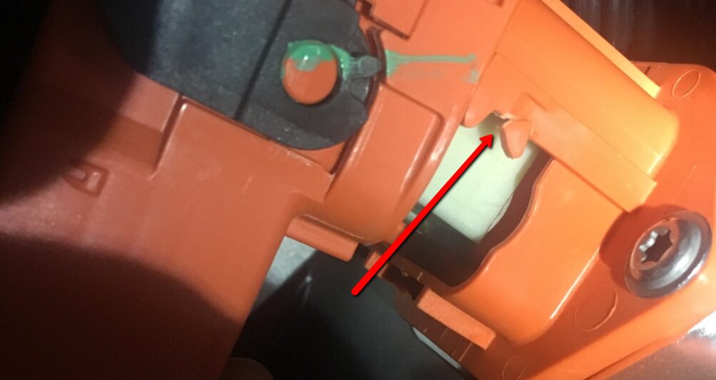
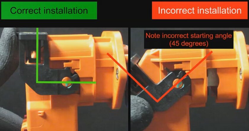
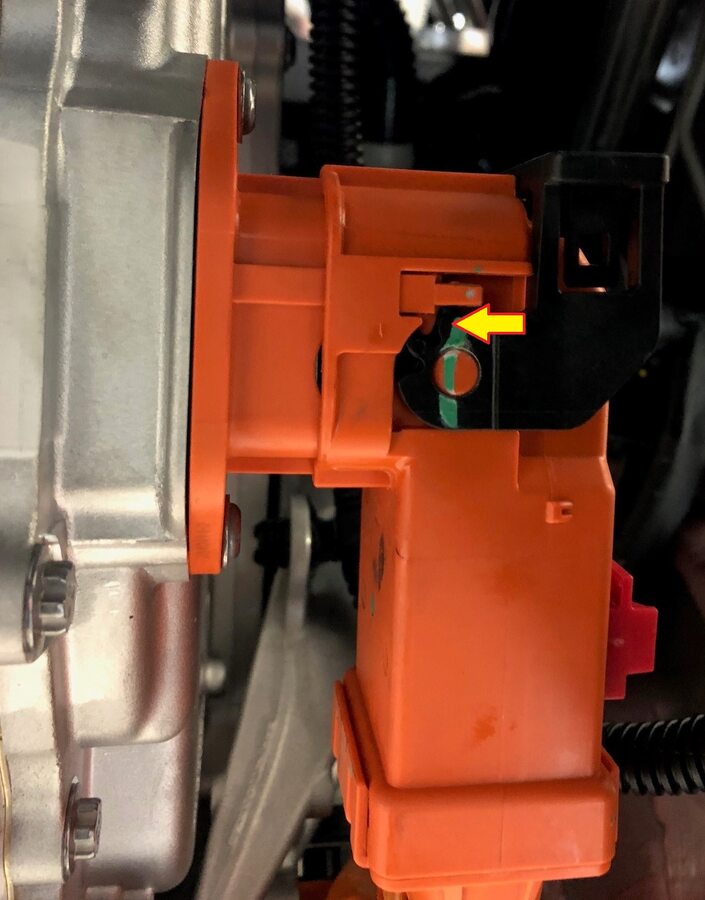
Install FDU HV harness connector to
FDU.
Remarque1x connector, Ensure the connector is installed far enough on the FDU manifold so the manifold alignment tooth is making contact with the connector lever.
-
Secure FDU HV harness connection to
FDU.
Remarque1x locking connector, Verify lever is in the upright and open position, Carefully seat connector and allow lever to engage, Fully secure lever and engage red locking tab, Do not damage connector or header.
-
Install bolt securing FDU HV harness
to FDU.
Remarque1x bolt, 10mm, 10 Nm.
-
Remove plastic bracket securing HV
connectors to body.
Remarque3x clips.
-
Connect A/C compressor HV harness
connector.
Remarque1x connector, 2 stage lock tab, Apply abrasion tape to harness if not present.
-
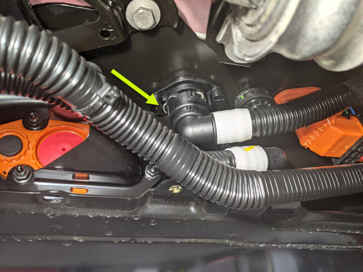
Connect PTC HV connector to HV cable
then reinstall bracket.
Remarque1x connector, 2 stage lock tab, Apply abrasion tape to harness if not present.

-
Install front skid plate onto HV
battery.
Remarque2x tabs, Slide tabs onto front of HV battery.
-
Install the bolts securing the front
skid plate to the HV battery.
Remarque4x bolts, E10, 13 Nm.
-
Install the clips securing the front
LH and RH wheel liners to the front skid plate.
Remarque2x push clips.
-
Position front aero shield to vehicle
and install nuts.
Remarque2x nuts, 15mm, 5 Nm.

-
Apply Loctite 222 onto front aero
shield bolts and install outer fasteners to front aero shield.
Remarque9x bolts, 10mm, 5 Nm.

-
Lower vehicle fully and move rack arms
away from vehicle.
RemarqueRemove M3 lift adapters from body and install body plugs.
-
Push vehicle away from lift.
RemarqueRecommend assistance, Note this vehicle can only be safely pushed for a very short distance and at very slow speed, Chock wheels.
- Open all four doors.
-
Install positive 12V output from PCS
cable and torque nut.
Remarque1x nyloc nut, 13mm, 9 Nm, Install new nut, Mark nut after torque, Make sure rubber boot is not pinched between cable terminal.
-
Install positive 12V output
cover.
Remarque1x cover.
-
Install DCDC ground busbar.
-
Install bolt securing DCDC ground
busbar to body.
Remarque1x bolt, 13mm, 20 Nm.

-
Install nut securing DCDC ground
busbar to HV battery.
Remarque1x nyloc nut, 13mm, 9 Nm, Install new nyloc nut.

-
Install bolts securing RH inner
ancillary bay rail to the ancillary bay cover.
Remarque2x bolts, T40, 24 Nm.
-
Install bolts securing LH inner
ancillary bay rail to the ancillary bay cover.
Remarque2x bolts, T40, 24 Nm.
-
Connect 3PH chargeport inlet harness
to HV header.
Remarque1x connector, Rotate lever arm and secure locking tab.
-
Clean HV connector contact surface of
residual Penetrox.
RemarqueAllow 1 minute dry time after wiping away Penetrox, New busbar comes with penetrox applied to HV connector.
-
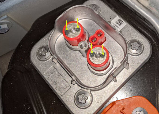
Apply Penetrox onto HV connector
joints.
RemarqueApply 2 drops of Penetrox A-13 about 5mm in diameter to either side of the hole on both leads, Spread evenly to verify the contact surface is fully covered.
-
Position chargeport busbar connector
to HV header.
Remarque4x guide tabs, Recommend assistance, Shift rear end of busbar assembly upward to help ease installation, If excessive force is required to seat busbars, they may have been bent. Inspect for damage and replace if necessary.

-
Install bolts securing chargeport
busbar connector to HV header.
Remarque2x bolts, 10mm, 9 Nm.

-
Install edge support bracket.
Remarque2x bolts, 10mm, 10 Nm, 1x clip.
-
Inspect HV insulating gloves.
RemarqueCheck gloves for damage prior to each use, Refer to service document TN-15-92-003 R5, for information on inspecting HV gloves.

-
Put on HV insulating gloves and
leather over gloves.
RemarqueMake sure to wear Electrical Protective Gloves any time Hioki tester is used.

-
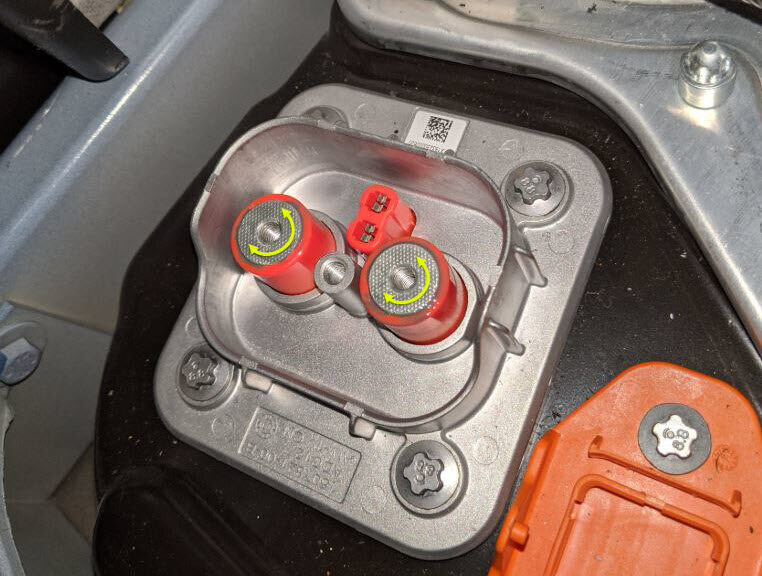
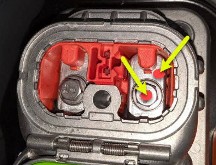
Perform Hioki resistance test at each
HV joint from HV busbar lead to bolt head.
Remarque2x HV joints, The acceptable resistance is between 0.050 mΩ (50 μΩ) and 0.195 mΩ (195 μΩ).If the resistance is greater than 0.195 mΩ (195 μΩ), there is too much resistance in the High Voltage joint. Remove the fastener, clean areas with isopropyl alcohol, install fastener back and test again.If the resistance is lower than 0.050 mΩ (50 μΩ), reposition the probes and measure again.If the resistance is repeatedly between 0.00 mΩ and 0.050 mΩ (50 μΩ), Hioki test passed, proceed to next step.
- Remove HV insulating gloves.
-
Install fastener securing busbar cover
access door.
Remarque1x bolt, 10mm, 9 Nm.
-
Install HV cap to ancillary bay.
Remarque1x cap.
-
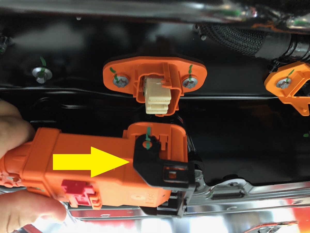
Remove logic cap and connect the HVC
logic connector.
Remarque1x connector, 1x cap, Align connector then pull the handle to locking position get connector fully seated.

-
Install 12V cap to ancillary bay.
Remarque1x cap.

-
Connect 12V negative terminal.
Remarque1x nut, 10mm, 6 Nm.
-
Press and hold park button to release
EPB service mode.
RemarqueRemove wheel chocks if necessary.
-
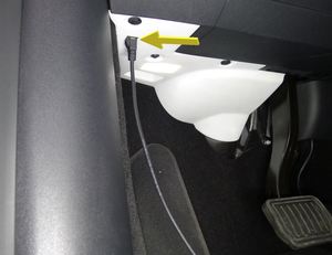
Connect to vehicle using Toolbox
3.0.
RemarqueVehicle connection is integrated into drivers footwell cover, Open Toolbox 3 website and establish connection to the vehicle.
- Select ‘Actions/Autodiag’ and search for ‘Thermal’.
-
Select "Start Thermal Fluid Fill/Drain
(Coolant only)", click Run and allow routine to complete.
RemarqueSelect ‘X’ at top right of window to close once complete, Verify vehicle is in Series via Garage > Vitals > Thermal tab > Coolant loops, Thermal Fluid Fill/Drain routine has a 5 hour limit, After 5 hours routine must be performed again.
-
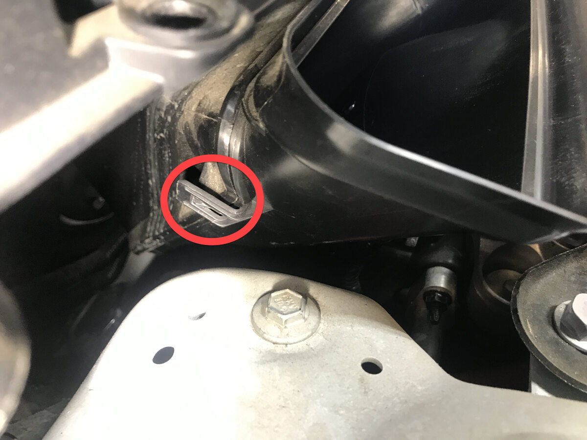
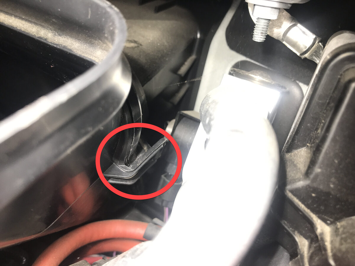
Remove HVAC plenum outer duct.
Remarque2x clips.


-
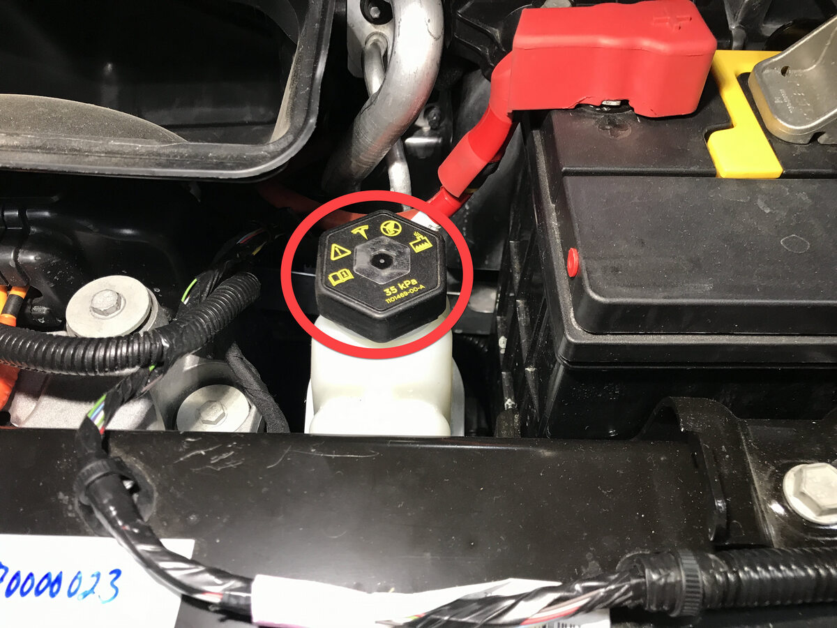
Remove superbottle cap.
-
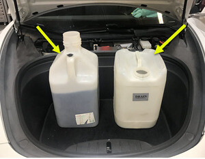
Place empty coolant container into
front storage area.
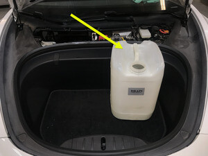
-
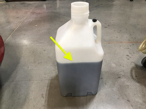
Fill container with at least 15L of
coolant.
-
Place filled coolant container into
front storage area.
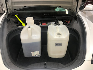
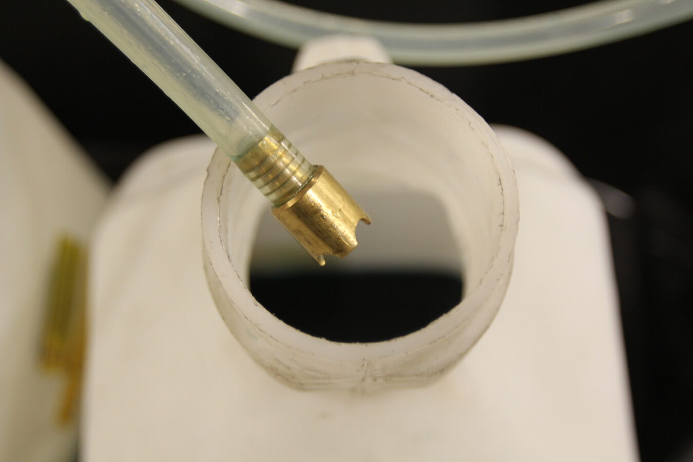
-
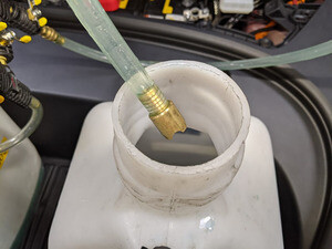
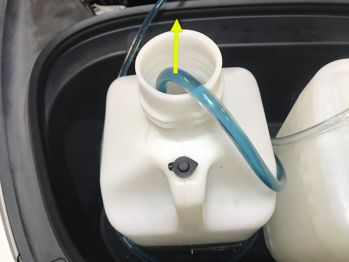
Place refill hose inside filled
coolant container .
RemarqueMake sure hose end is fully submerged into coolant.
-
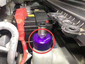
Install vacuum refill cap onto
superbottle assembly.
-
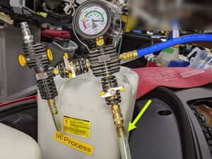
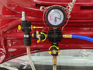
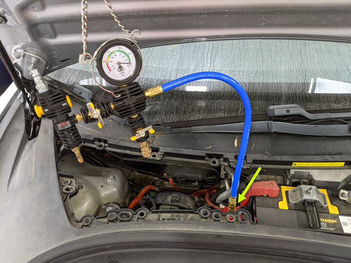
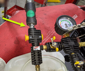
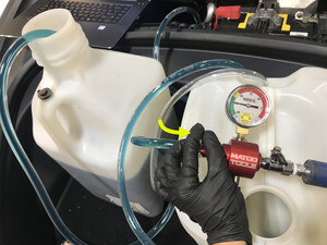
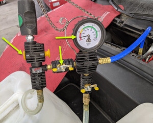
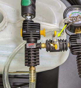
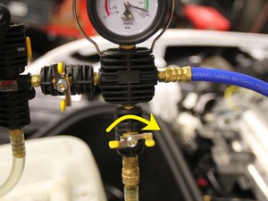
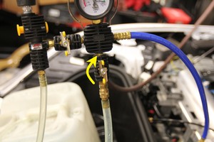
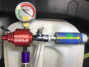
Setup vacuum refill tool.
RemarqueVerify all valves on refill tool are in the closed position, See image for clarity.
-
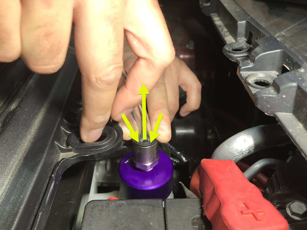
Install vacuum refill hose into refill
cap on coolant bottle.
RemarquePerform push-pull-push test to verify hose is fully installed.
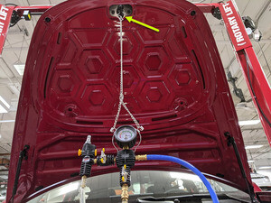
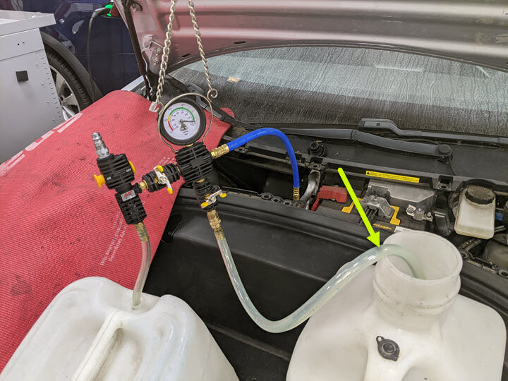
-
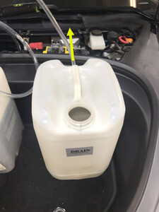
Position overflow hose into empty
container.
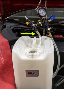
-
Place refill hose inside filled
coolant container .
RemarqueMake sure hose end is fully submerged into coolant.
-
Connect shop air supply to coolant
refill tool.
RemarqueIf not already done, Verify refill valve is set to off.
-
Slowly open the coolant refill valve
to allow coolant to be drawn into the coolant refill hose, Close the valve when the hose
is full of coolant.
RemarqueThis purges trapped air from the hose.

-
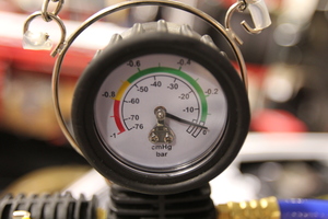
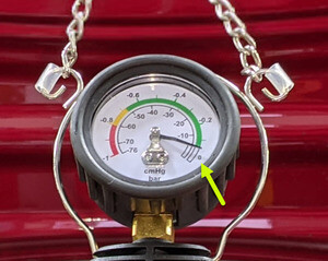
Open air inlet valve to draw a vacuum,
Once gauge stabilizes, Fully close valve.
RemarqueGauge stabilizes roughly (60-70 cmHg), Vacuum should not drop after the valves are closed.
-
Once the gauge reads zero, close the
coolant refill valve.
-
Once the gauge reads zero, close the
refill valve.

-
Slowly open the refill valve to allow
coolant to be drawn into the system.
RemarqueMake sure hose end of refill hose is fully submerged during entire process.
-
Once the gauge reads zero, close the
refill valve.
-
Disconnect shop air supply from
coolant refill tool.
-
Remove coolant refill hose from
coolant container.
-
Remove coolant overflow hose from
coolant container.
-
Remove vacuum refill hose from refill
cap on superbottle.
RemarquePush down on black ring to release hose and pull hose up to remove.
-
Remove coolant overflow hose from
coolant container.
-
Remove both coolant containers from
inside underhood area.
- Select ‘Actions/Autodiag’ tab and search for ‘Purge'.
-
Select
‘TEST_VCFRONT_X_THERMAL-COOLANT-AIR-PURGESearch for routine in ToolboxCoolant Air PurgeThermal / Coolant System - Coolant Purge Starthv / Front Drive Inverter Replacement - Coolant Air Purgehv / Rear Drive Inverter Replacement - Coolant Air Purgehv / Rear Left Drive Inverter Replacement - Coolant Air Purgehv / Rear Right Drive Inverter Replacement - Coolant Air Purgehv / Front Drive Unit Replacement - Coolant Air Purgehv / Rear Drive Unit Replacement - Coolant Air PurgeThermal / Actions - Coolant Purge Stop or Coolant Purge Start ’, click ‘Run’, and allow routine to
complete.
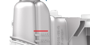
RemarqueMake sure vehicle is not in drive state, Plan is still running despite the stop message, Coolant pumps will be audible, Test lasts approximately 10 mins, Speeds can be monitored in garage under PT Thermal tab, Idle speed = ~1500 RPM, Test will vary speeds from 3500-6500 RPM and actuate valve between SERIES and PARALLEL, Putting vehicle into drive state will stop this routine, If speeds hover at 7000 RPM, that means the pumps are air locked, perform vacuum fill again, Continue to add coolant and purge until the coolant level reaches between the NOM and MAX Lines on the bottle, Select ‘X’ at top right of window to close once complete.
-
Inspect coolant level and top off as
necessary.
RemarqueEnsure that the fluid level is 5mm above the Max line.
-
Install superbottle cap.

-
Install HVAC plenum outer duct.
Remarque2x clips, Align tab at bottom of duct before securing clips.

-
Select
‘TEST-SELF_VCFRONT_X_THERMAL-PERFORMANCESearch for routine in ToolboxThermal System Performance TestThermal / Actions - Test Thermal Performancehv / Front Drive Inverter Replacement - Thermal System Testhv / Rear Drive Inverter Replacement - Thermal System Testhv / Rear Left Drive Inverter Replacement - Thermal System Testhv / Rear Right Drive Inverter Replacement - Thermal System Testhv / Front Drive Unit Replacement - Thermal System Testhv / Rear Drive Unit Replacement - Thermal System Test’, click ‘Run’, and allow routine
tocomplete.
RemarqueSelect ‘X’ at top right of window to close once complete.
-
Remove HSD or RJ45 cable from Ethernet
port to disconnect Toolbox 3.0 from vehicle.
- Close RH rear door.
- Close LH rear door.
-
Close LH front door.
-
Remove lift arms from below
vehicle.
RemarqueLower rack arms fully and remove them from under vehicle.
- Open all four doors.
-
Torque LH rear HV battery interior
bolt.
Remarque1x bolt, 16mm, 66 Nm, Lift up LH rear main carpet for access if necessary.
- Move LH front seat backward.
-
Torque LH front footwell HV battery
bolts.
Remarque2x bolts, EP20, 136 Nm.

-
Fold the LH front main cabin carpet
back to original position.
RemarqueMove front edge down and slide back section up to ease positioning, Install seat harness into clip.

-
Install clips securing LH front main
cabin carpet to vehicle.
Remarque3x push clips, Number of clips on newer vehicles may vary.
-
Move LH front seat forward.
-
Torque RH rear HV battery interior
bolt.
Remarque1x bolt, 16mm, 66 Nm, Lift up RH rear main carpet for access if necessary.

- Move RH front seat backward.
-
Torque RH front footwell HV battery
bolts.
Remarque2x bolts, EP20, 136 Nm.
-
Unfold RH front main cabin carpet back
to original position.
RemarqueMove front edge down and slide back section up to ease positioning, Install seat harness into clips.
-
Install clips securing the RH front
main cabin carpet to footwell area.
Remarque3x push clips, Number of clips may vary on older vehicles.
- Move RH front seat forward.
-
Install clips and secure Velcro
holding rear main cabin carpet to vehicle.
Remarque4x push clips, The number of clips on newer vehicles may vary.
-
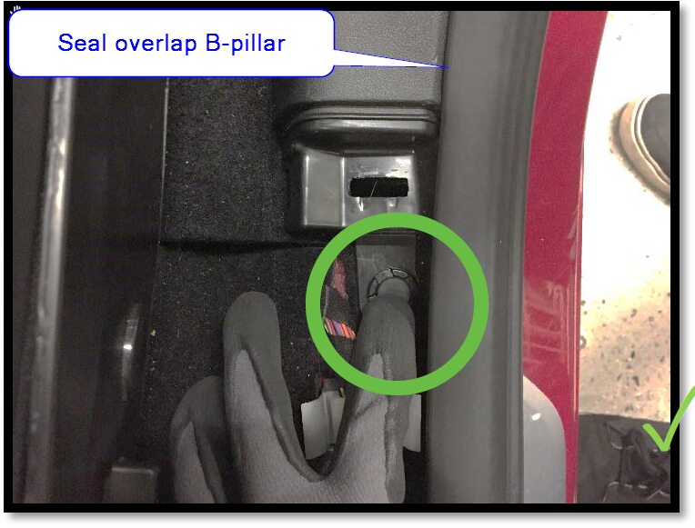
Install the LH lower B-pillar
assembly.
Remarque1x push clip, 6x clips, Align the bottom guide tab to its slot then press the bottom clips, Work your way to top clips, Install the front push clip then make sure the seal correctly overlaps the trim.
-
Install the LH upper B-pillar
assembly.
Remarque4x clips, Lower the seat belt slider to align it with the B-pillar panel, Insert top portion of upper B-pillar under the headliner to align the clips, Press the bottom to fully seat upper B-pillar to lower B-pillar, Make sure the seal correctly overlaps the trim.
-
Install the LH rear door sill trim
panel.
Remarque3x clips, 1x guide tab, Align the guiding tab to slot, Then push downward to install the clips after aligning them, Make sure the seal sits overlapping the trim. Newer vehicles may not be equipped with metal bracket and a foam insert will be present the bottom of trim piece.
-
Fold the 60 seat in down
position.
RemarqueProtect the seat cushion if necessary.
-
Install bolster plastic bracket to LH
side bolster.
Remarque2x tabs, Install new bolster bracket.
-
Install LH side bolster.
Remarque1x clip, 1x tab, Align the bottom tab then push inward to install.
-
Fold the 60 seat into vertical
position.
RemarqueRemove seat cushion protection.

-
Install the RH lower B-pillar
assembly.
Remarque1x push clip, 6x clips, Align the bottom guide tab to its slot then press the bottom clips, Work your way to top clips, Install the front push clip then make sure the seal correctly overlaps the trim.
-
Install the RH upper B-pillar
assembly.
Remarque4x clips, Lower the seat belt slider to align it with the B-pillar panel, Insert top portion of upper B-pillar under the headliner to align the clips, Press the bottom to fully seat upper B-pillar to lower B-pillar, Make sure the seal correctly overlaps the trim.
-
Install RH rear door sill trim
panel.
Remarque3x clips, 1x guide tab, Align the guiding tab to slot, then push downward to install the clips after aligning them, Make sure the seal sits overlapping the trim.
-
Fold the 40 seat in down
position.
RemarqueProtect the seat cushion if necessary.
-
Install bolster plastic bracket to RH
side bolster.
Remarque2x tabs, Install new bolster bracket.
-
Install RH side bolster.
Remarque1x clip, 1x tab, Align the bottom tab then push inward to install.
-
Fold the 40 seat into vertical
position.
RemarqueRemove seat cushion protection.

-
Connect 2nd row seat cushion harness
and install 2nd row seat cushion.
Remarque2x connectors, 2x clips, Insert the seat belt buckles through the holes, Slide rear cushion inward then align front guide tabs to locking tabs, Make sure cushion is fully seated with push & pull test near clips.
-
Install 2nd row floor mat into
vehicle.
- Move RH front seat backward.
-
Install RH console side panel
carpet.
Remarque1 tab, 12x clips, Position side panel and align the front tab. Push the console panel from the front towards the rear.
-
Install RH front floor mat.
-
Connect RH footwell assembly
connectors.
Remarque2x connectors.
-
Install clips securing RH footwell
assembly.
Remarque4x push clips .
-
Install RH lower A-pillar trim.
Remarque1x clip, 2 guide tabs, Align 2 front tabs then align slot with harness bracket and then push rear clip to secure to lower B-pillar.
-
Install clip for RH lower A-pillar
trim.
Remarque1x push clip.
-
Install RH mid A-pillar assembly.
Remarque1x clip, 1x tab, Align bottom tab then push on top clip to fully seat mid A-pillar, Make sure seal seat on top of trim.
-
Install RH IP end cap.
Remarque3x clips.
- Move LH front seat backward.
-
Install LH console side panel
carpet.
Remarque1 tab, 12x clips, Position side panel and align the front tab. Push the console panel from the front towards the rear.
-
Install LH front floor mat.
-
Install connectors to LH footwell
cover and position for installation, securing front tabs to driver air bag
assembly.
Remarque3x tabs, 1x Ethernet connector, 1x puddle light connector, APAC specific vehicles have an additional OBDII connector.
-
Install screw and clips securing LH
footwell cover.
Remarque2x push clips, 1x screw, T20, 2.5 Nm.
-
Install LH lower A-pillar trim.
Remarque2x clip, 3 guide tabs, Align the 2 front tabs then align the slot with harness bracket and then push rear clip to secure to lower B-pillar, Fully seat seal along trim.
-
Install clip for LH lower A-pillar
trim.
Remarque1x push clip.

-
Install LH mid A-pillar assembly.
Remarque1x clip, 1x tab, Align the bottom tab then push the top clip to fully seat mid A-pillar, Pull seal over trim.
-
Install LH IP end cap.
Remarque3x clips.

- Move LH front seat to original position.
- Move RH front seat to original position.
-
Install cabin intake upper duct
assembly.
Remarque4x clips, Heat pump vehicles have 3x clips.

-
Install rear apron.
Remarque12x clips .

- Close hood.
- Raise all windows.
-
Close all four doors.
RemarqueUnlatch rear doors before closing.
-
Install RH rocker panel lower cover
into position.
Remarque10x clips.
-
Install clips securing the RH rocker
panel lower cover to wheel liners.
Remarque4x push clips.
-
Install bolts securing RH rocker panel
lower cover to body.
Remarque4x bolts, 10mm, 5 Nm, Secure 4x covers, The number of fasteners on newer vehicles may vary.

-
Install LH rocker panel lower cover
into position.
Remarque10x clips.
-
Install clips securing the LH rocker
panel lower cover to wheel liners.
Remarque4x push clips.
-
Install bolts securing LH rocker panel
lower cover to body.
Remarque4x bolts, 10mm, 5 Nm, Secure 4x covers, The number of fasteners on newer vehicles may vary.