17/06/2024 14:11:11
Joint à rotule – arrière – inférieur – fusée arrière – gauche (retirez et remplacez)
 Code de correction
31031832 0.54 NOTE: Unless otherwise explicitly
stated in the procedure, the above correction code and FRT reflect all of the work
required to perform this procedure, including the linked procedures. Do not stack correction codes unless
explicitly told to do so.NOTE: See Flat Rate
Times to learn more about FRTs and how they are created. To provide feedback on
FRT values, email LaborTimeFeedback@tesla.com. NOTE: See Protection individuelle to make sure wearing proper PPE when
performing the below procedure.
Code de correction
31031832 0.54 NOTE: Unless otherwise explicitly
stated in the procedure, the above correction code and FRT reflect all of the work
required to perform this procedure, including the linked procedures. Do not stack correction codes unless
explicitly told to do so.NOTE: See Flat Rate
Times to learn more about FRTs and how they are created. To provide feedback on
FRT values, email LaborTimeFeedback@tesla.com. NOTE: See Protection individuelle to make sure wearing proper PPE when
performing the below procedure.
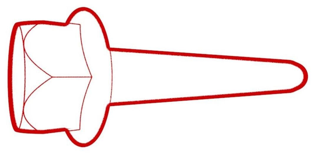
- M3/Y Knuckle Ball Joint Replacement Tool
- Inspectez le véhicule pour une usure anormale des pneus qui pourrait indiquer qu'un alignement du parallélisme des roues est nécessaire. Prenez en note toutes vos constatations.
- Open the LH front door and lower the LH front window.
- Remove the LH rear wheel. See Ensemble de roue (retrait et installation).
- Remove the LH rear suspension cover. See Couvercle - suspension arrière - gauche (retirez et remplacez).
-
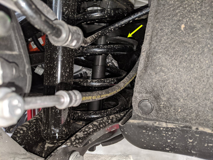
Install a spring compressor onto the LH
rear coil spring.
RemarqueTooling may vary per service center. Reference photos for clarification.
-
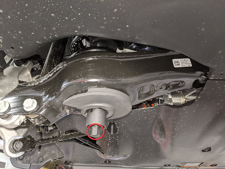
Remove the bolt and nut that attach the
LH rear lower aft link to the knuckle.
Conseil : Nous recommandons l’utilisation des outils suivants :
- Douille de 21 mm
- 21 mm combination wrench
-
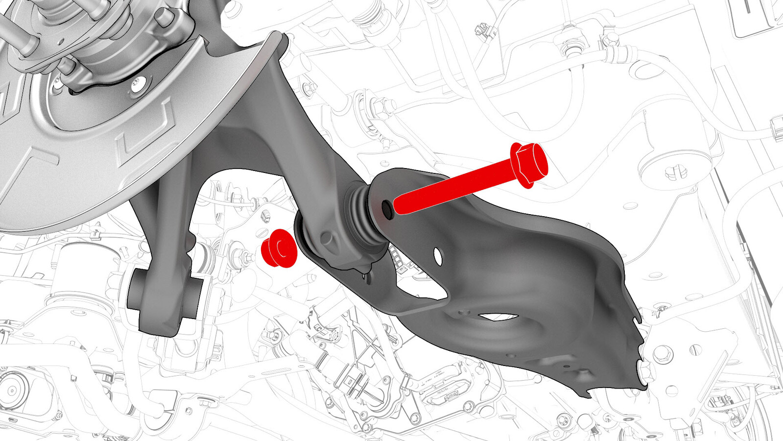
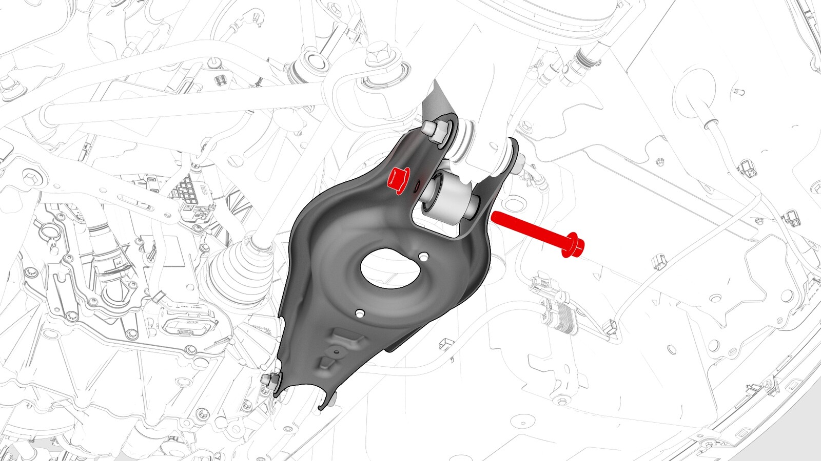
Remove the bolt and nut that attach the
LH rear damper to the LH rear lower aft link.
RemarqueLower the aft link and allow it to hang. Make sure the coil spring is compressed sufficiently to clear the upper spring seat.Conseil : Nous recommandons l’utilisation des outils suivants :
- Douille de 21 mm
- 21 mm combination wrench
-
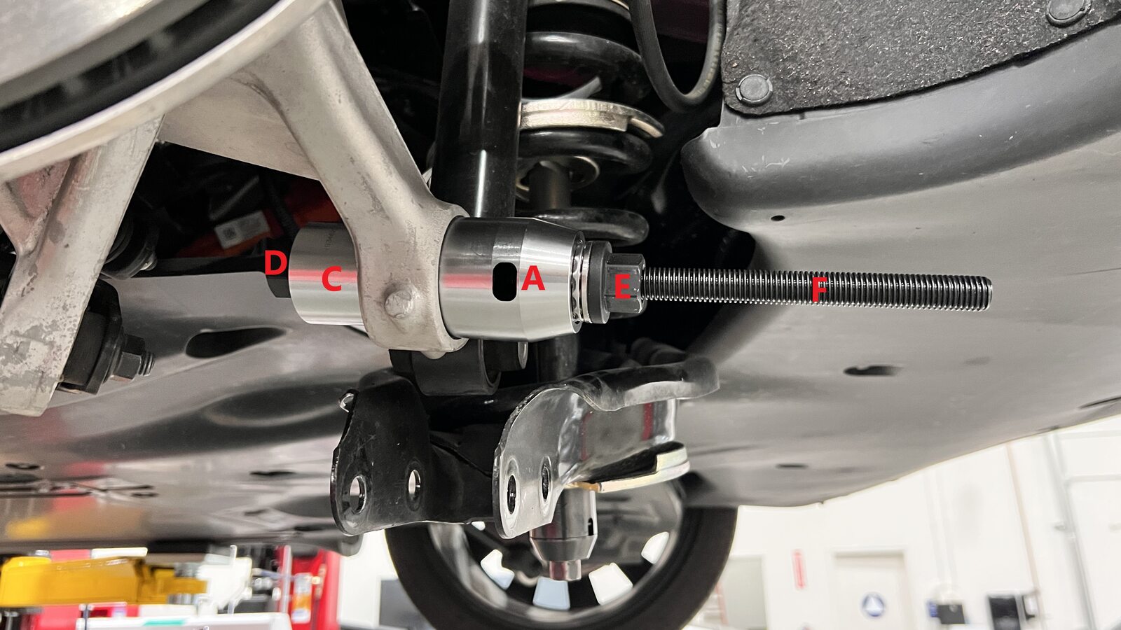
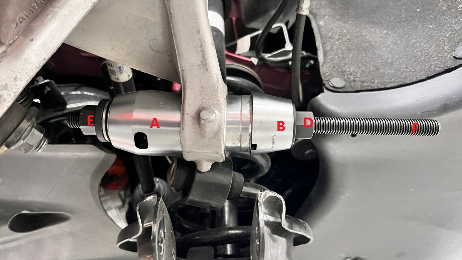
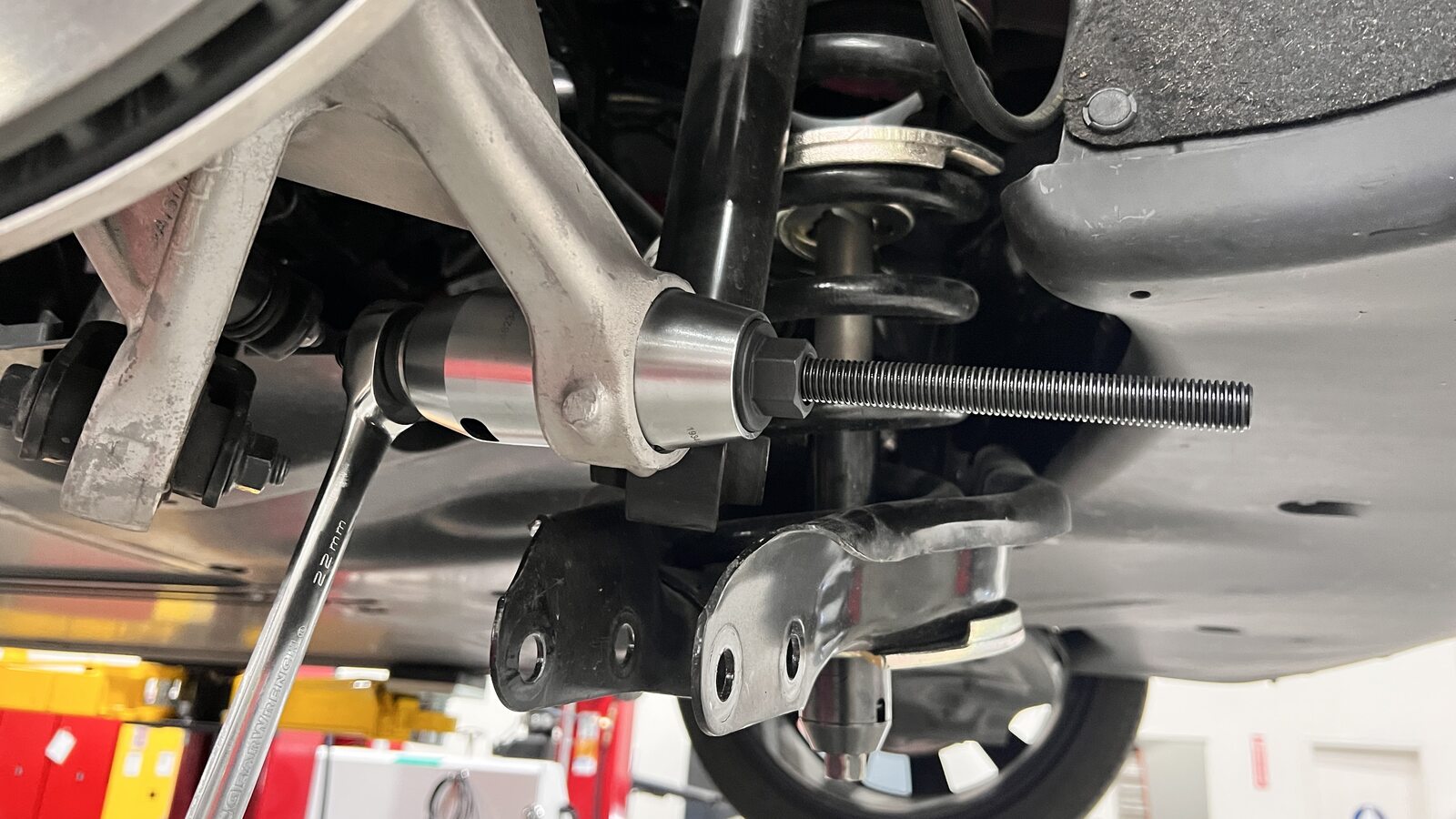
Install the knuckle ball joint
replacement tool onto the knuckle.
RemarqueMake sure the cups sit flush to the ball joint and knuckle surface.RemarqueThe ball joint will only press out towards rear of vehicle.RemarqueApply lubricant to threaded rod if dry.

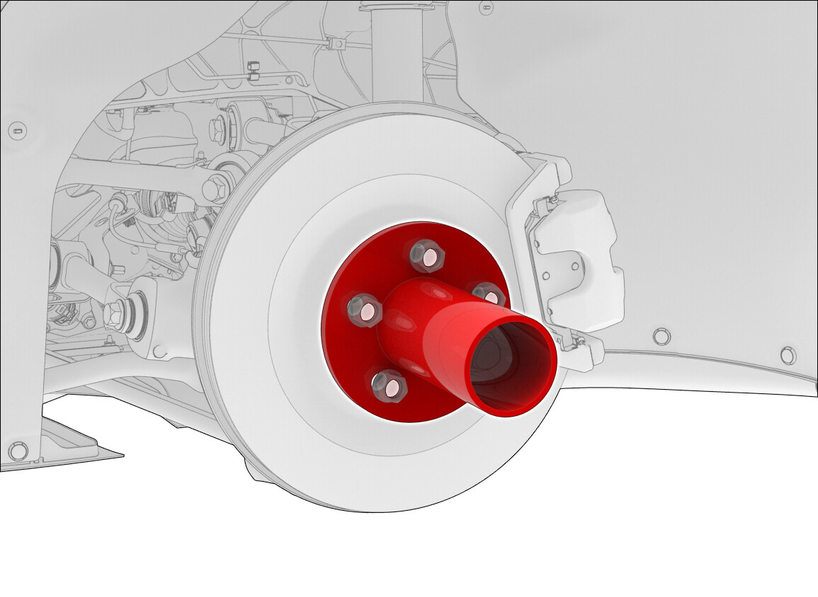
-
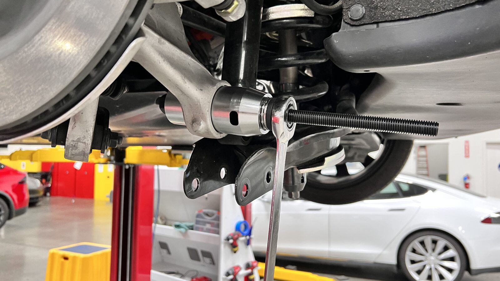
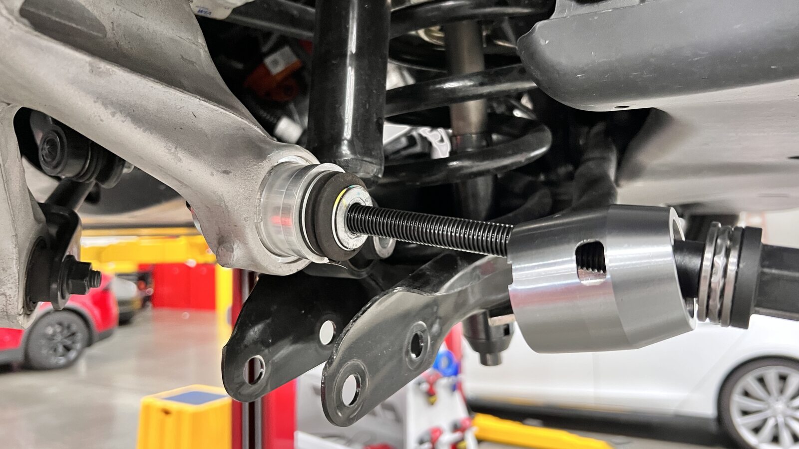
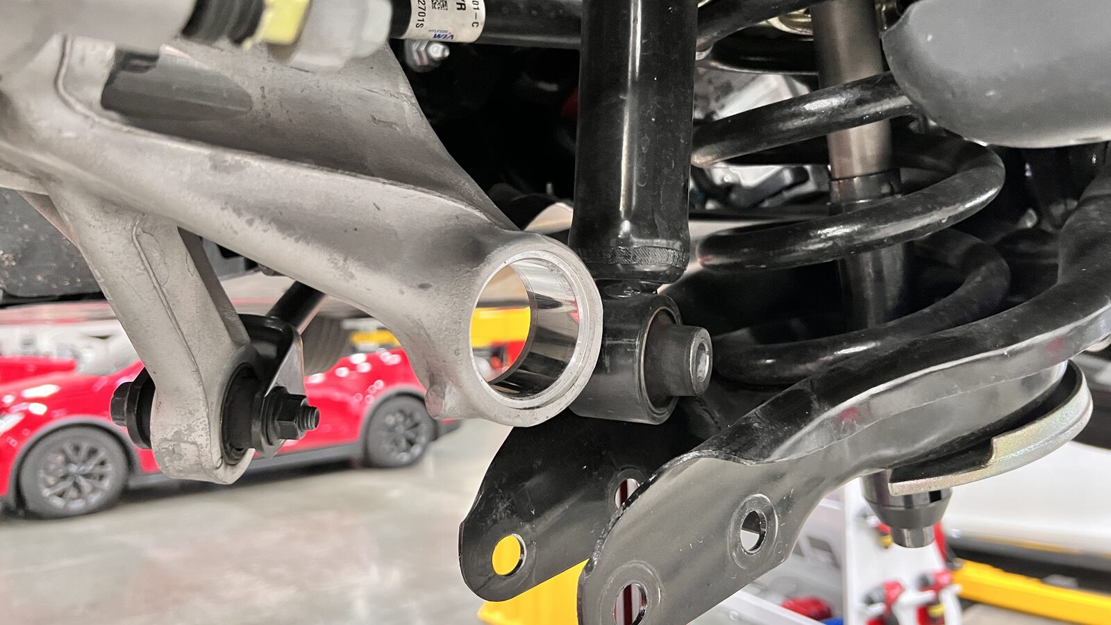
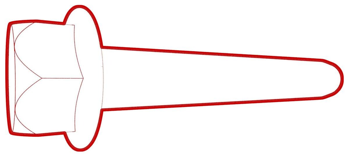
Press the LH rear knuckle lower rear
ball joint out of the knuckle.
RemarqueThe ball joint should press out with minimal resistance. If met with high resistance, inspect the tool cups for misalignment.RemarqueUse the windows in the receiving cup to monitor progress.
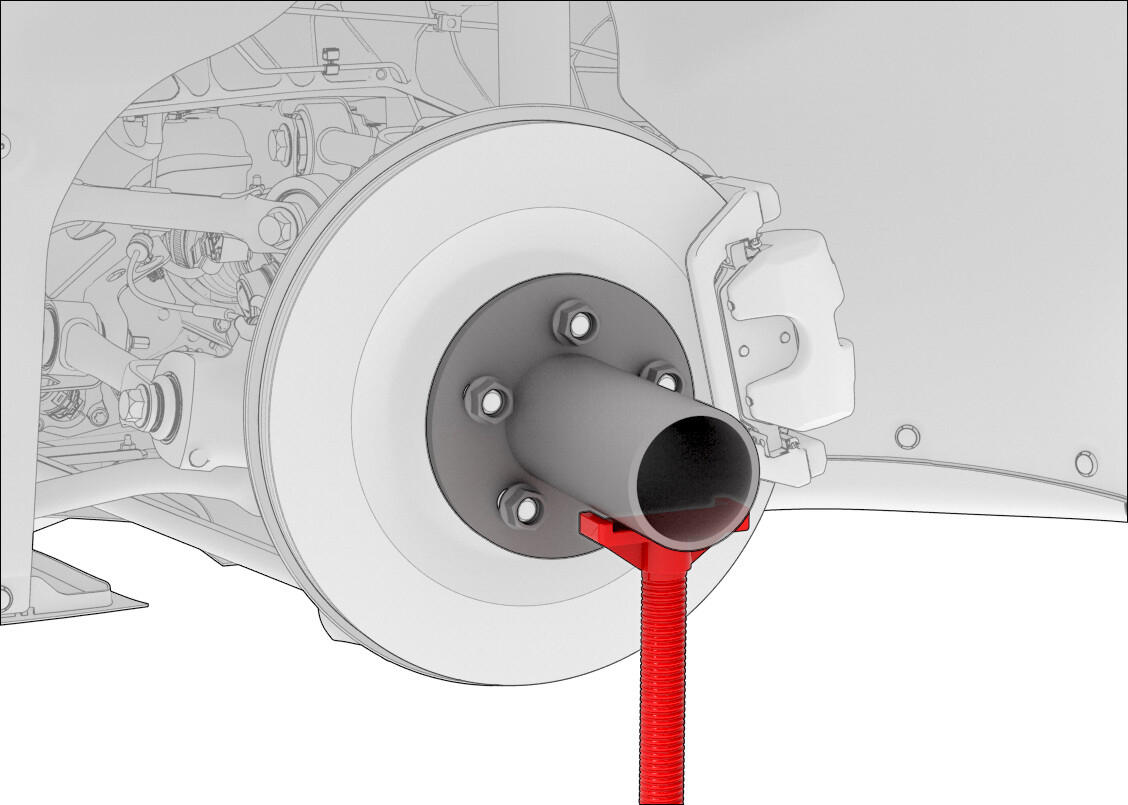
-
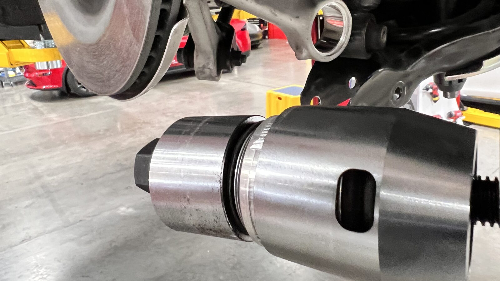
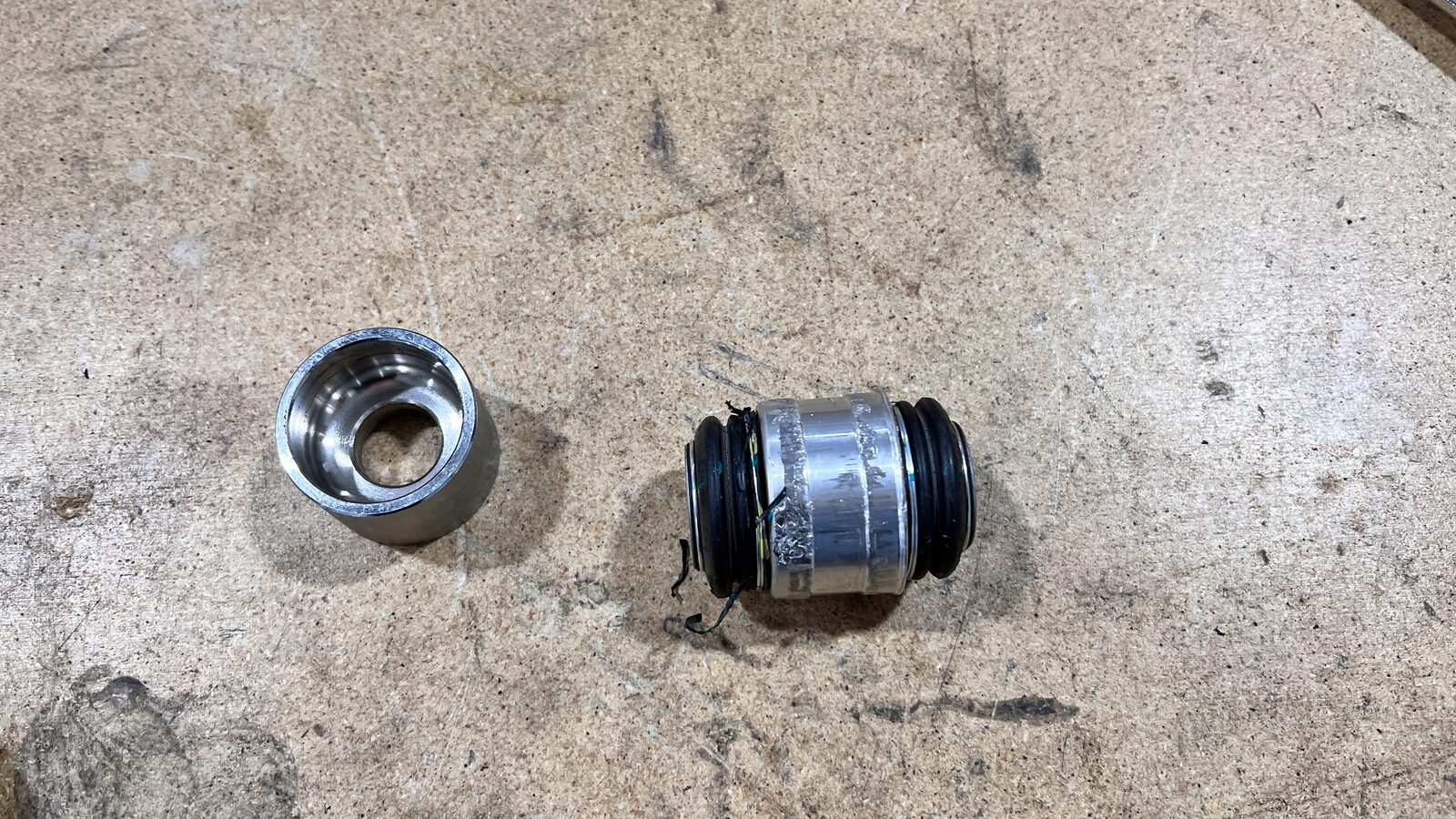
Remove the knuckle ball joint
replacement tool from the assembly.
RemarqueDiscard ball joint once removed.RemarqueIf the ball joint sticks in the removal cup, gently tap it out with a punch.
-
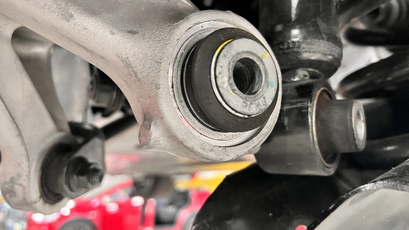
Position a new LH rear knuckle lower
rear ball joint at the lead in of the knuckle bore.
RemarqueMake sure ball joint is sitting square to machined surface.
-
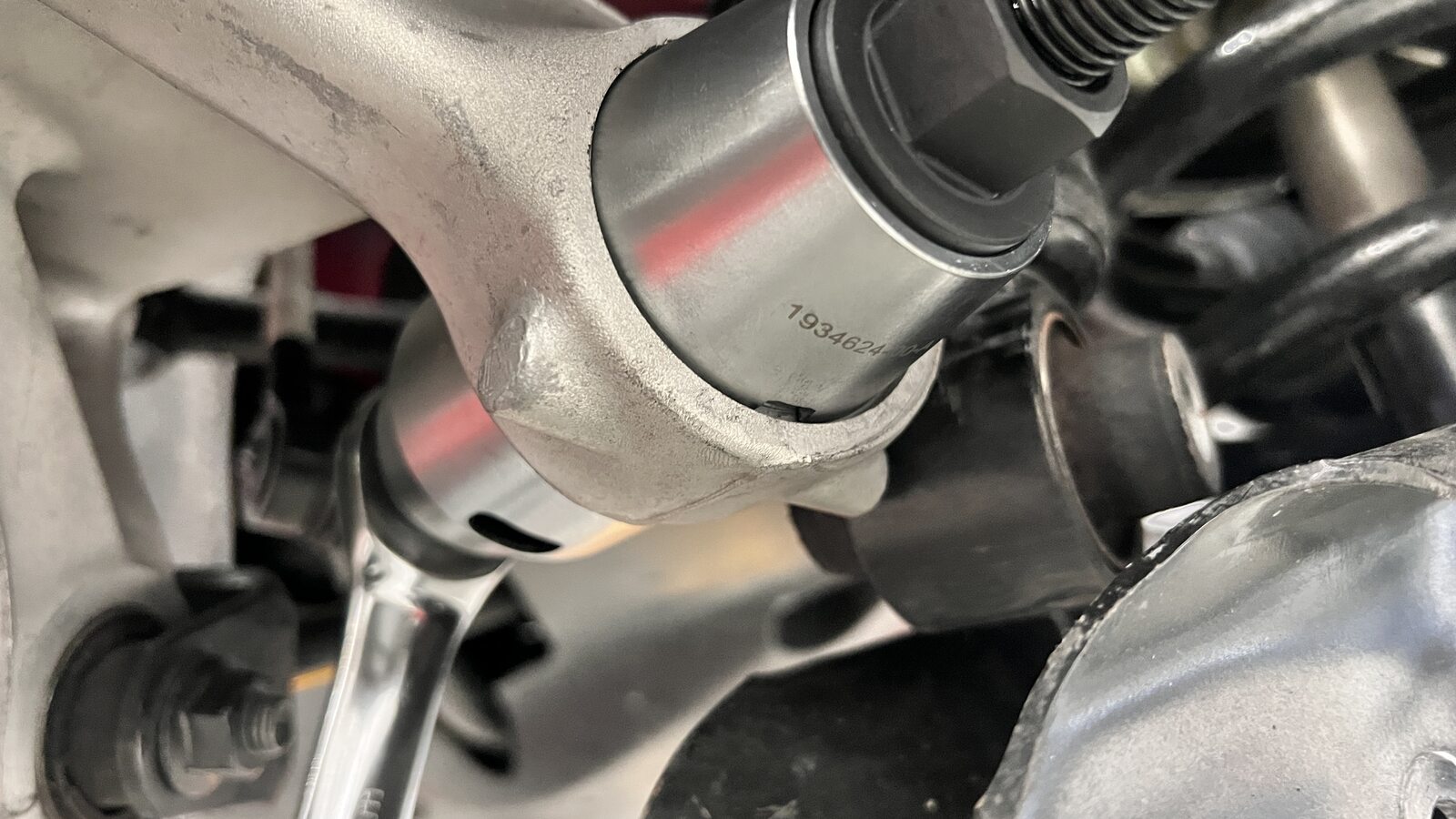
Install the knuckle ball joint replacement tool.
RemarqueMake sure the cups sit flush to the ball joint and knuckle surface.RemarqueThe ball joint will only press in towards the front of the vehicle.RemarqueMake sure the nut with bearing is not used on the installation cup.
-
Press the LH rear knuckle lower rear
ball joint into the knuckle.
RemarqueThe ball joint should press in with minimal resistance. If met with high resistance, inspect the tool cups for misalignment.RemarqueUse the notch in the installation cup to monitor progress.RemarqueWhen nearing the end of the bore, the installation cup may need to be re-aligned to meet machined surface.

-
Remove the knuckle ball joint
replacement tool.
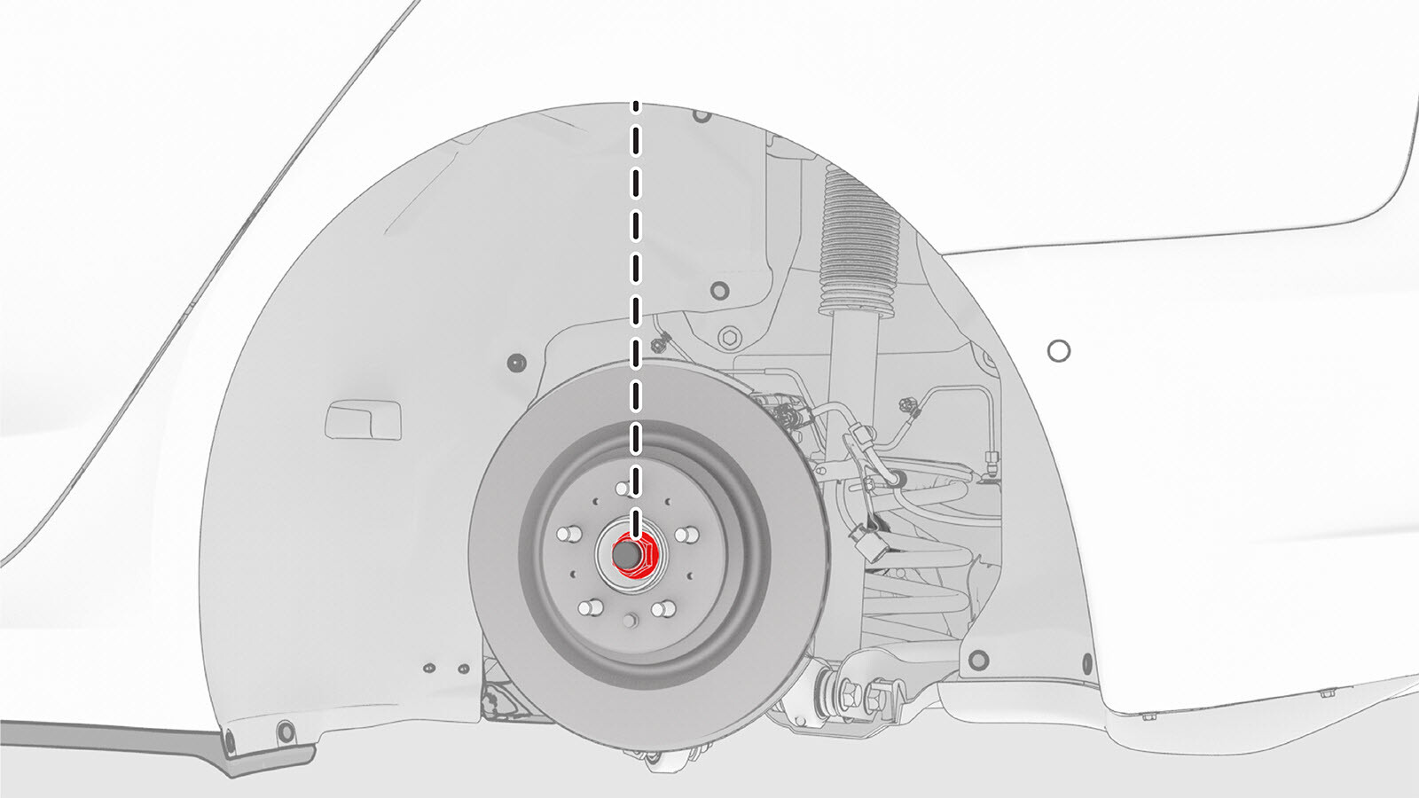
-
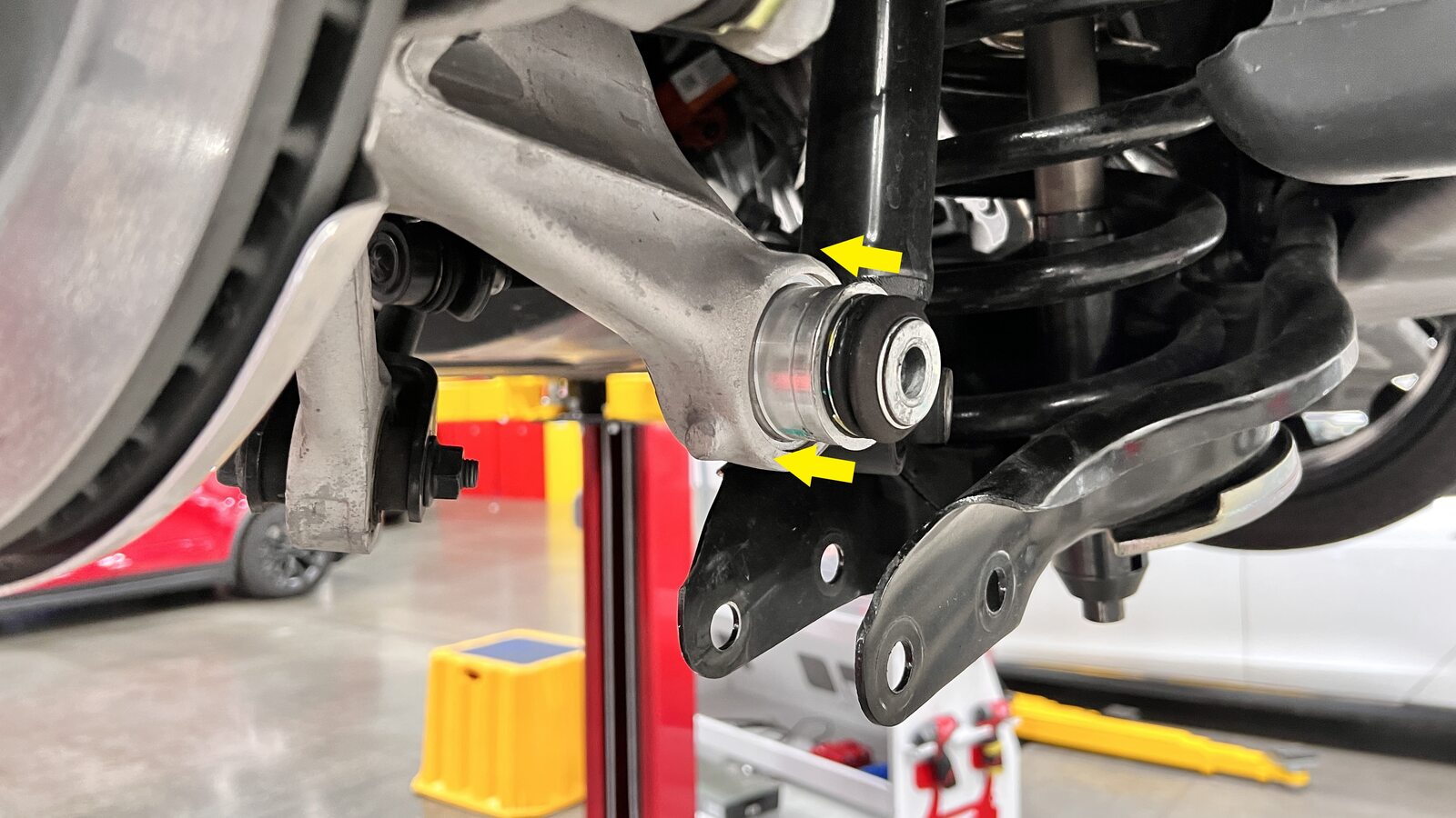
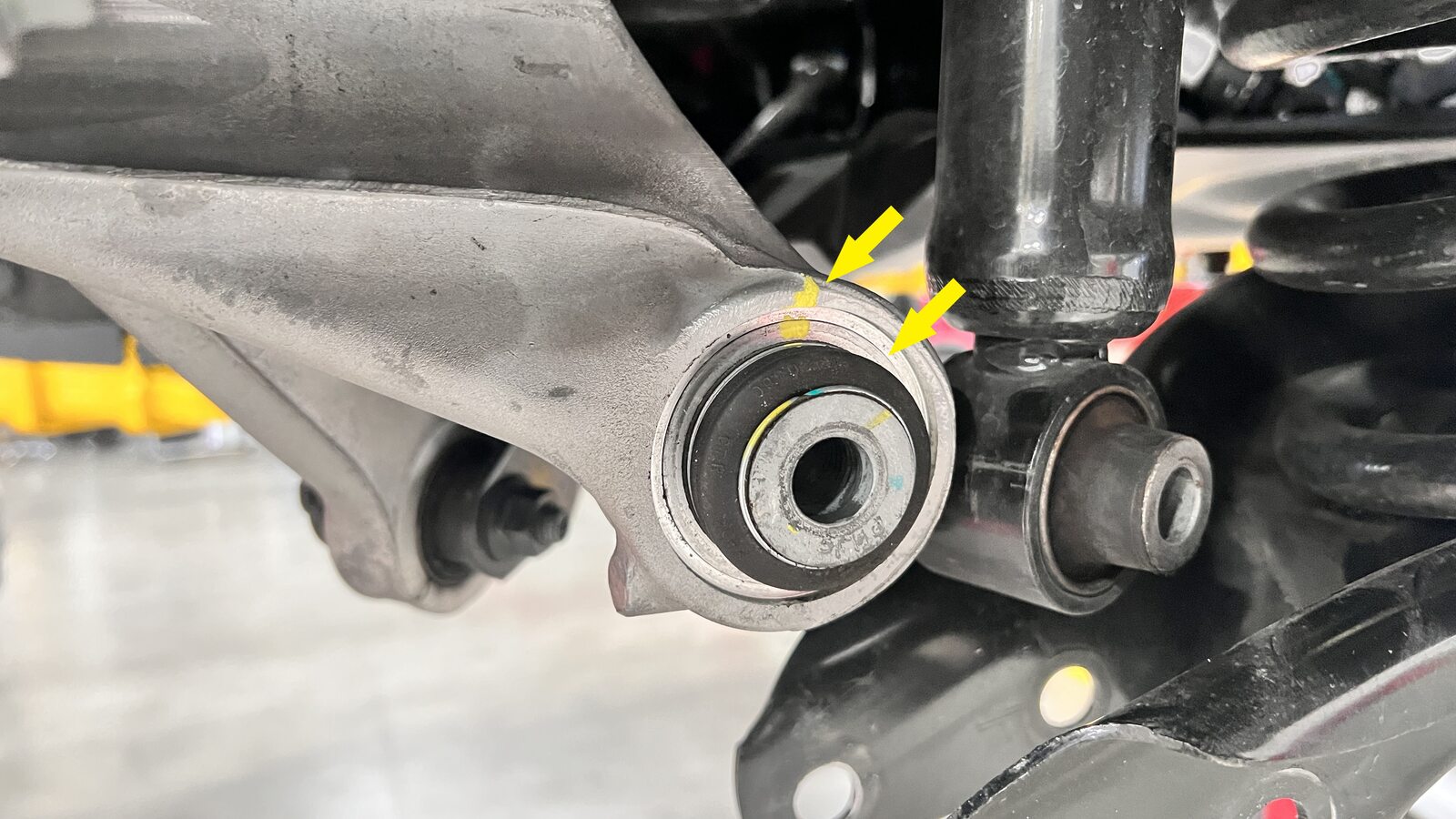
Verify that the ball joint is fully
installed, and then mark the surface with a paint pen.
RemarqueThe machined surface should be near flush with the ball joint.
-
Install and hand-tighten the bolt and nut that attach the LH rear damper to the LH rear
lower aft link.
-
Install and hand-tighten the bolt and
nut that attach the LH rear lower aft link to the LH rear knuckle.
-
Install a hub jack adapter onto the LH
rear hub and hand-tighten the lug nuts.
-
Move the support stand to support the
hub jack adapter.
 RemarqueUse the rear ride height torque gauge to verify that the rear suspension is set to ride height specifications and adjust the support stand or spring compressor tool , if necessary.
 -
Measure the distance between the bottom
of the LH rear quarter panel to the center of the LH rear axle to make sure that the rear
suspension is set to ride height: The distance should measure 378
mm.
-
Tighten the bolt that attaches the LH
rear lower aft link to the LH rear knuckle. Mark the bolt with a paint pen after the bolt
is tightened.
 115 Nm (84.8 lbs-ft)
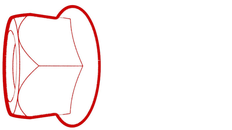 115 Nm (84.8 lbs-ft)RemarqueNous recommandons l’utilisation des outils suivants :
- Douille de 21 mm
- 21 mm combination wrench
-
Tighten the bolt and nut that attach the
LH rear damper to the LH rear lower aft link. Mark the bolt with a paint pen after the
bolt is tightened.
 115 Nm (84.8 lbs-ft)
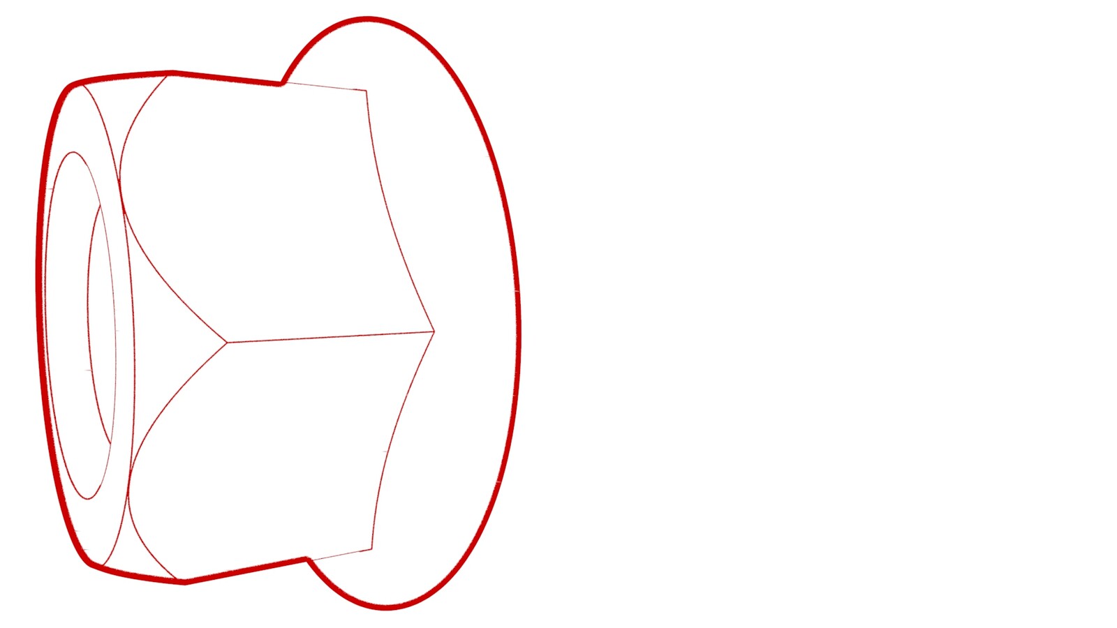 115 Nm (84.8 lbs-ft)RemarqueNous recommandons l’utilisation des outils suivants :
- Douille de 21 mm
- 21 mm combination wrench
-
Remove the support stand from the hub
jack adapter.
-
Remove the lug nuts that attach the hub
jack adapter, and then remove the hub jack adapter from the LH rear hub.
-
Remove the spring compressor from the LH
rear spring.
- Install the LH rear suspension cover. See Couvercle - suspension arrière - gauche (retirez et remplacez).
- Install the LH rear wheel. See Ensemble de roue (retrait et installation).
- Raise the LH front window and close the LH front door.
- Refer to the Alignment Requirement tables to determine if an alignment check or full adjustment is necessary. See Exigences de réglage de la géométrie - Suspension.