Assembly - Bulkhead Resolver Connector - Rear Drive Unit (4DU) (Remove and Replace)
 Code de correction
4001040802
FRT
0.48
REMARQUE : À moins d’indications explicites contraires dans la procédure, le code de correction et le temps à taux fixe (FRT) connexe représentent tout le travail à accomplir pour cette procédure, y compris les procédures connexes. N’appliquez pas plusieurs codes de correction à la fois, à moins qu’il vous soit explicitement indiqué de le faire.
REMARQUE : Consultez Temps forfaitaires pour en apprendre plus à propos des temps forfaitaires et de leur création.
NOTE : Consultez Protection individuelle pour vous assurer de porter l’équipement de protection individuelle adéquat lorsque vous effectuez la procédure ci-dessous.
REMARQUE : Voir Précautions ergonomiques pour consulter les pratiques de travail sécuritaires et saines.
Spécifications de couple
| Description | Valeur de couple | Outils recommandés | Réutiliser/remplacer | Remarques |
|---|---|---|---|---|
| Boulons (x3) qui fixent l'ensemble de connecteur de résolveur de cloison |
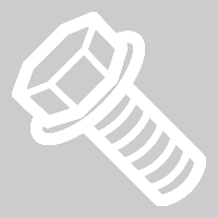 8 Nm (5.9 lbs-ft) |
|
Remplacer | 1015888-00-C |
| Bouchon de vidange d'huile |
15 Nm (11.1 lbs-ft) |
|
Réutiliser |
Retirer
- Remove the rear aero shield panel. See Aero Shield - Rear (Remove and Replace).
-
Release the hose clip from the resolver cover, and then rotate the clip 90 degrees
counterclockwise to facilitate removal of the bulkhead resolver connector
assembly.
-
Release the locking tab and disconnect the resolver connector.
NoteMove the harness branch aside as needed.
-
Remove and discard the bolts (x3) that secure the bulkhead resolver connector
assembly, and then remove the assembly from the vehicle.
TipUse of the following tool(s) is recommended:
- Torx T25 bit
Installer
- Lightly coat the o-rings on the new connector with clean KAF1 oil.
-
Install new bolts (x3) that secure the bulkhead resolver connector assembly.8 Nm (5.9 lbs-ft)TipUse of the following tool(s) is recommended:
- Torx T25 bit
-
Connect the resolver connector and engage the locking tab.
-
Install the hose clip to the resolver cover, and then rotate the clip 90 degrees
clockwise to secure the clip.
- Position an oil drain container to underneath the drive unit.
- Remove the fill plug from the drive unit. See .Fill/Drain Plug (Remove and Replace)
-
Release the oil drain plug from the drive unit.
TipUse of the following tool(s) is recommended:
- 8 mm hex
-
Disconnect the oil pump connector.
NoteDo not push down on the red tab. Pull the red tab to disengage the lock, then pull it again to release the connector.
-
Connect the 12V power supply to the
oil pump switchbox, and then secure the oil pump switchbox to the oil pump
connector.
-
Run the oil pump power supply for 1
minute and drain the remaining oil from the drive unit.
NoteTake precaution because the oil will shoot out at a wide angle. Adjust the position of the oil drain container as needed. Do not run oil pump dry for extended period of time.
- Release the power supply and the oil pump switchbox from the oil pump connector.
-
Install the oil drain plug to the drive unit.15 Nm (11.1 lbs-ft)NoteVerify the O-ring is not damaged and replace the plug as needed.TipUse of the following tool(s) is recommended:
- 8 mm hex
-
Set up the fill kit with KAF1 and fill
the measuring container to 2.5 L (2500 ml).
Note
- The 4DU drive unit takes 2.3 L of fluid. However, add extra oil to the container to prevent underfill and additional air being injected.
- Only use KAF1 fluid for the 4DU drive unit. Do not interchange or mix oil types.
-
Insert the output hose of the fluid
transfer pump into the fill hole of the rear drive unit until fully seated, then pull
back 5 mm.
-
Fully submerge the input hose of the
fluid transfer pump into the measuring container.
-
Pump 2.3L/2300mL of KAF1 gearbox fluid
into the rear drive unit.
NoteMake sure the input hose end remains submerged, so that air is not pumped into the gearbox.NoteWhen properly filled, there should be 200ml or less of gearbox fluid left in the measuring container.
- Install the fill plug to the drive unit. See .Fill/Drain Plug (Remove and Replace)
-
Connect the oil pump connector and engage the locking tab.
- Spray the working area of the rear drive unit with brake cleaner, and then wipe off residual fluid with a clean shop towel.
- Remove the oil drain container from underneath the rear drive unit.
- Install the rear aero shield panel. See Aero Shield - Rear (Remove and Replace).
- Locally connect a laptop with Toolbox 3 to the vehicle. See Toolbox (connecter et déconnecter).
- On the laptop, click the Actions tab, type "Oil Pump Low pressure Test - Rear Drive Unit" into the search field, click TEST-SELF_DIR_X_OIL-PUMP-PRESSUREvia Toolbox:(link), click Run, and allow the routine to complete.
- Disconnect the laptop.
- Exit Service Mode. See Mode Entretien Plus.