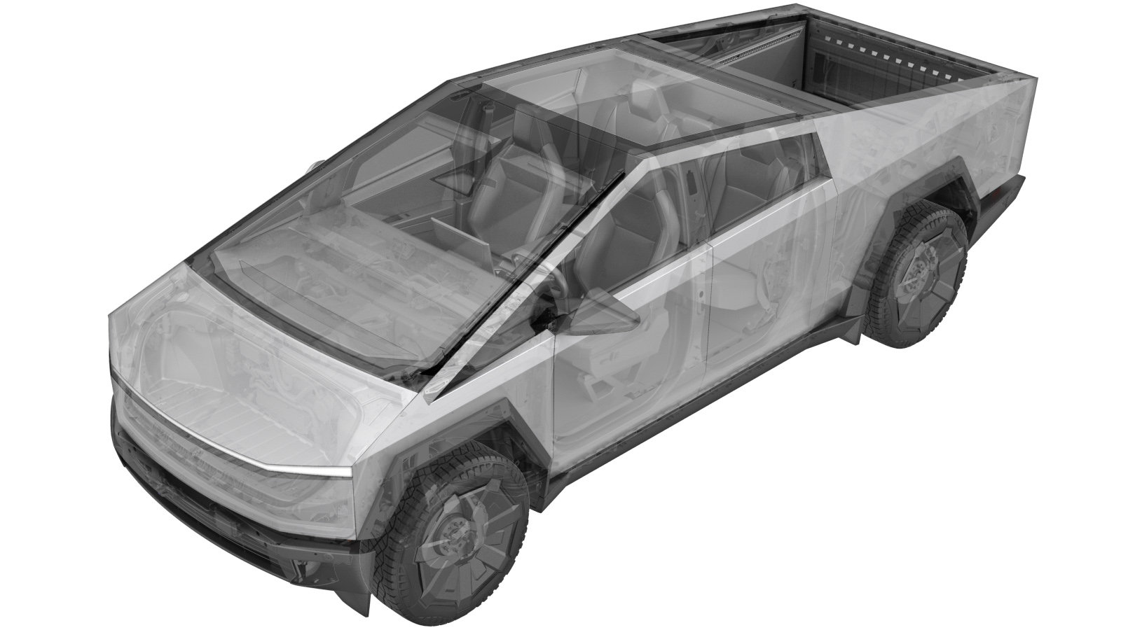
MV Controller - Rear (Long Range) (Remove and Replace)
 Code de correction
NEW
REMARQUE : À moins d’indications explicites contraires dans la procédure, le code de correction et le temps forfaitaire ci-dessus représentent tout le travail à être fait pour cette procédure, notamment les procédures connexes. N’appliquez pas plusieurs codes de correction à la fois, à moins qu’il vous soit explicitement indiqué de le faire.
REMARQUE : Consultez Temps forfaitaires pour en apprendre plus à propos des temps forfaitaires et de leur création. Vous pouvez transmettre par courriel vos commentaires relatifs aux valeurs des temps forfaitaires à ServiceManualFeedback@tesla.com.
REMARQUE : Consultez Protection individuelle pour vous assurer de porter l’équipement de protection individuelle adéquat lorsque vous effectuez la procédure ci-dessous.
REMARQUE : Voir Précautions ergonomiques pour consulter les pratiques de travail sécuritaires et saines.
Code de correction
NEW
REMARQUE : À moins d’indications explicites contraires dans la procédure, le code de correction et le temps forfaitaire ci-dessus représentent tout le travail à être fait pour cette procédure, notamment les procédures connexes. N’appliquez pas plusieurs codes de correction à la fois, à moins qu’il vous soit explicitement indiqué de le faire.
REMARQUE : Consultez Temps forfaitaires pour en apprendre plus à propos des temps forfaitaires et de leur création. Vous pouvez transmettre par courriel vos commentaires relatifs aux valeurs des temps forfaitaires à ServiceManualFeedback@tesla.com.
REMARQUE : Consultez Protection individuelle pour vous assurer de porter l’équipement de protection individuelle adéquat lorsque vous effectuez la procédure ci-dessous.
REMARQUE : Voir Précautions ergonomiques pour consulter les pratiques de travail sécuritaires et saines.
- 2025-06-21: Released new procedure.
-
Open LH front door
RemarquePush LH B-pillar door trigger to release
-
Lower LH front window
-
Open LH rear door
RemarquePush LH C-pillar door trigger to release
-
Lower LH rear window
-
Open powered front trunk
RemarqueVia exterior switch or UI
-
Remove rear underhood apron
Remarque9x clips
-
Remove 2nd row floor mat
-
Fold up 2nd row 60 seat
RemarquePull tether to release then lift up until locked in place
-
Partially release LH lower C-pillar trim
Remarque1x clip, 1x datum
-
Open RH rear door
RemarquePush RH C-pillar door trigger to release
-
Lower RH rear window
-
Fold up 2nd row 40 seat
RemarquePull tether to release then lift up until locked in place
-
Partially release RH lower C-pillar trim
Remarque1x clip, 1x datum
-
Remove rear wall lower trim
Remarque2x push clips, 4x clips, Remove outermost push clips, then pull straight forward to release inner clips
-
Power down vehicle via UI
RemarqueVerify EPBs are engaged, Select charge port icon to ensure drive state is disengaged then power down vehicle via Controls > Safety > Power Off
-
Disconnect FRL connector then disconnect MV battery connector
Remarque2x connectors, Release locking tab then disconnect FRL connector, Slide eCPA to left then lift lever to release MV battery connector, Early production trucks may have black FRL connector, Release eCPA by pushing down to unlock and slide red locking tab, Wait 2 minutes for electrical circuits to discharge before disconnecting modules
-
Release rear MV controller locking cover
Remarque1x bolt, 8mm, 6 Nm, Do not remove locking cover, Loosen until bolt spins freely, Double check that bolt and locking cover are fully released before attempting to release any MV connectors, Plastic Locking CoverUse hand tools on any plastic locking covers, The locking cover may release crooked causing it to get stuck, secure bolt a few turns to loosen the tension then release bolt while assisting plastic locking cover by gently prying on the side that's stuck, Metal Locking CoverYou can use power tools, Quickly disconnecting locking cover helps connectors remove symmetrically,
-
Release connector J3 X0052 from rear vehicle controller
Remarque1x connector, 2x tabs, 1x clip, Do not remove locking cover, Each connector has two tabs one on the top right side and one on the left lower side of the connector head, You need to press both tabs in order for the connector head to clear locking cover and release successfully, Using a pocket screwdriver to press one of the connector tabs while pressing the other one yourself makes this process easier
-
Release rear vehicle controller connectors
Remarque3x connectors, 6 tabs, Do not remove locking cover, Depress tabs on top and bottom of each connector to release from locking cover, You need to press both tabs in order for the connector head to clear locking cover and release successfully, Using a pocket screwdriver to press one of the connector tabs while pressing the other one yourself makes this process easier
-
Disconnect etherloop connector
Remarque1x connector, Release locking tab
-
Remove LH vehicle controller
Remarque2x nuts, 10mm, 13 Nm, 1x bolt, 10mm, 10 Nm
-
Install rear MV controller
Remarque2x nuts, 10mm, 13 Nm, 1x bolt, 10mm, 10 Nm
-
Connect etherloop connector
Remarque1x connector, Engage locking tab
-
Secure remaining rear MV controller connectors
Remarque3x connectors, 6x tabs, Ensure connectors are aligned before securing bracket, Carefully insert connectors through locking covers, Gently wiggle connector heads to ensure they are correctly inserted, Connectors should be slightly loose but tab engagement will prevent them from removing, Consider that pins need to be alighned correctly before you drive the locking cover bolts
-
Secure connector J3 X0052 to rear vehicle controller locking frame
Remarque1x connector, 2x tabs, 1x clip, Carefully insert connector through locking cover, Gently wiggle connector heads to ensure they its correctly inserted, Connector should be slightly loose but tab engagement will prevent it from removing, Consider that pins need to be aligned correctly before you drive the locking cover bolt
-
Secure rear MV controller locking cover
Remarque1x bolt, 8mm, 6 Nm, Ensure connectors are aligned before securing bracket, Secure locking cover bolt by hand initially to prevent thread strippingPlastic Locking CoverUse hand tools on any plastic locking covers, The locking cover may secure crooked causing it to get stuck, release bolt a few turns to loosen the tension then secure bolt while assist plastic locking cover by gently pushing on the side that's stuck, Push connectors too while driving the locking cover bolt to ensure correct seatingMetal Locking CoverYou can use power tools, Slowly drive locking cover, Ensure locking cover and bolt are seated fully
-
Inspect for any misalignment at rear ribs and apply abrasion tape if missing
RemarqueEnsure cable is lying flat without twist, Ensure cable is secured correctly to rib, Apply surface protection at seam of rearmost rib under backbone cable if missing
-
Install rear wall lower trim
Remarque2x push clips, 4x clips
-
Secure LH lower C-pillar trim
Remarque1x clip, 1x datum
-
Fold down 2nd row 60 seat
RemarquePull tether to release then pivot down until locked in place
-
Raise LH rear window
-
Close LH rear door
-
Install RH lower C-pillar trim
Remarque1x clip, 1x datum
-
Fold down 2nd row 40 seat
RemarquePull tether to release then pivot down until locked in place
-
Install 2nd row floor mat
-
Raise RH rear window
-
Close RH rear door
-
Connect FRL connector then connect MV battery connector
Remarque2x connectors, Connect FRL connector then secure locking tab, Position lever to secure MV battery connector then slide eCPA to right, Early production trucks may have black FRL connector, If power cycling vehicle then ensure at least 60 seconds has passed since powering down
-
Install rear underhood apron
Remarque9x clips, Adjust windshield seal as required
-
Close powered front trunk
RemarqueVia exterior switch or UI
- Exécutez la routine ODIN PROC_ICE_X_ENTER-SERVICE-MODEvia Toolbox: (link)
-
Reinstall software via UI
RemarqueVia Controls > Service Mode > Software Reinstall, Select Reinstall button at Software Reinstall dialogue box, Reinstall will begin immediately, Once firmware redeploy is complete, Verify release notes are present via UI
- Exécutez la routine ODIN PROC_ICE_X_EXIT-SERVICE-MODEvia Toolbox: (link)
-
Raise LH front window
-
Close LH front door
-
Remove vehicle from 4-post lift