Handschuhfach – Mit Knie-Airbags (Wärmepumpe) (Ausbauen und Ersetzen)
 Korrekturcode
14051022
HINWEIS: Sofern im Verfahren nicht ausdrücklich anders angegeben, spiegeln der obige Korrekturcode und die FRT den gesamten für die Durchführung dieses Verfahrens erforderlichen Aufwand wider, einschließlich der damit verbundenen Verfahren. Schichten Sie keine Korrekturcodes, wenn Sie nicht ausdrücklich dazu aufgefordert werden.
HINWEIS: Unter Richtzeiten erfahren Sie mehr über FRTs und darüber, wie sie erstellt werden. Für Rückmeldungen zu den FRT-Werten senden Sie bitte eine E-Mail an LaborTimeFeedback@tesla.com.
HINWEIS: Siehe Persönlicher Schutz, um sicherzustellen, dass Sie die richtige persönliche Schutzausrüstung tragen, wenn Sie das folgende Verfahren durchführen.
Korrekturcode
14051022
HINWEIS: Sofern im Verfahren nicht ausdrücklich anders angegeben, spiegeln der obige Korrekturcode und die FRT den gesamten für die Durchführung dieses Verfahrens erforderlichen Aufwand wider, einschließlich der damit verbundenen Verfahren. Schichten Sie keine Korrekturcodes, wenn Sie nicht ausdrücklich dazu aufgefordert werden.
HINWEIS: Unter Richtzeiten erfahren Sie mehr über FRTs und darüber, wie sie erstellt werden. Für Rückmeldungen zu den FRT-Werten senden Sie bitte eine E-Mail an LaborTimeFeedback@tesla.com.
HINWEIS: Siehe Persönlicher Schutz, um sicherzustellen, dass Sie die richtige persönliche Schutzausrüstung tragen, wenn Sie das folgende Verfahren durchführen.
Ausbauen
-
Open both front doors
-
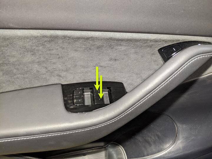
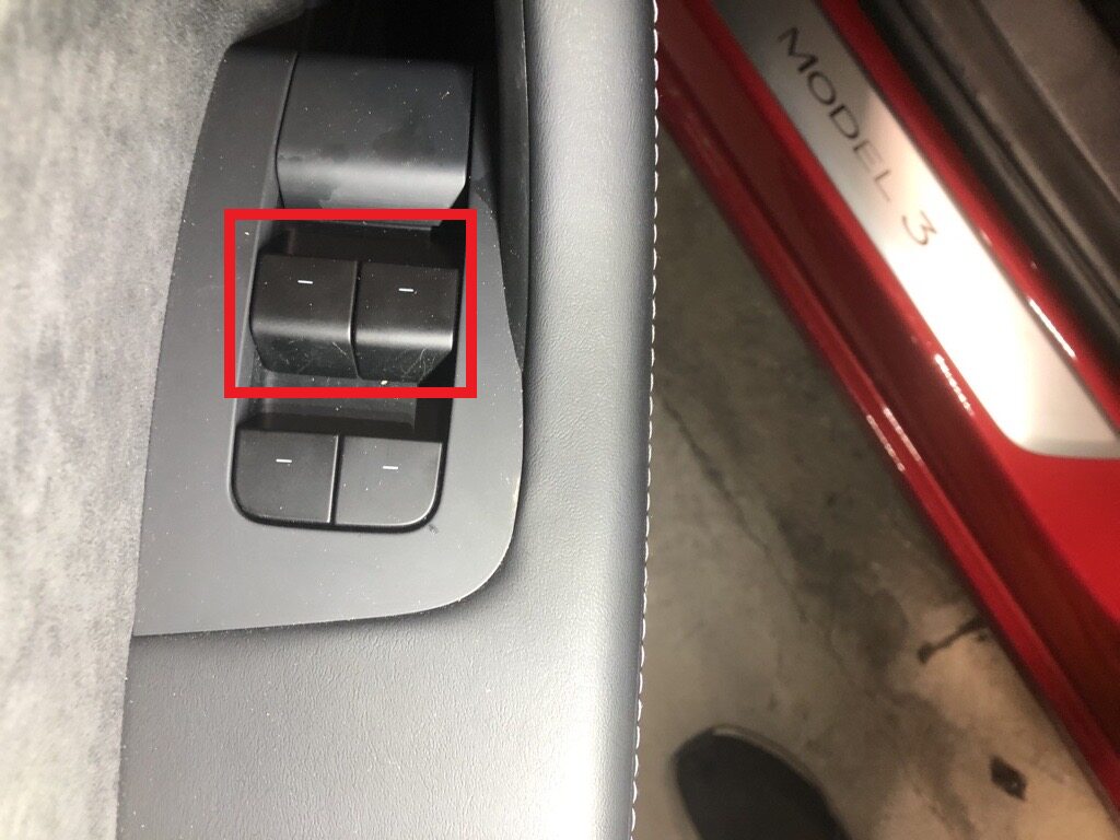
Lower both front windows
-
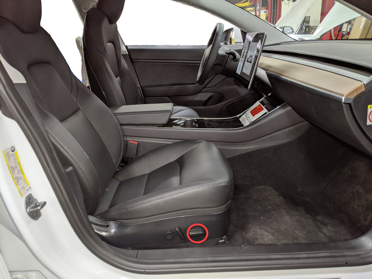
Move RH front seat backward
-
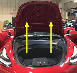
Open hood
AnmerkungPress "Open" button on touchscreen to release latch, Lift lid manually

-
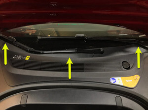
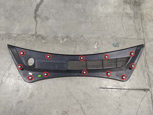
Remove rear apron
Anmerkung12x clips, Only store rear apron visible face upwards

-
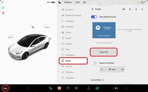
Power off vehicle from center
display
AnmerkungVia Controls > Safety > Power Off, Select Power Off button at warning dialogue box

-
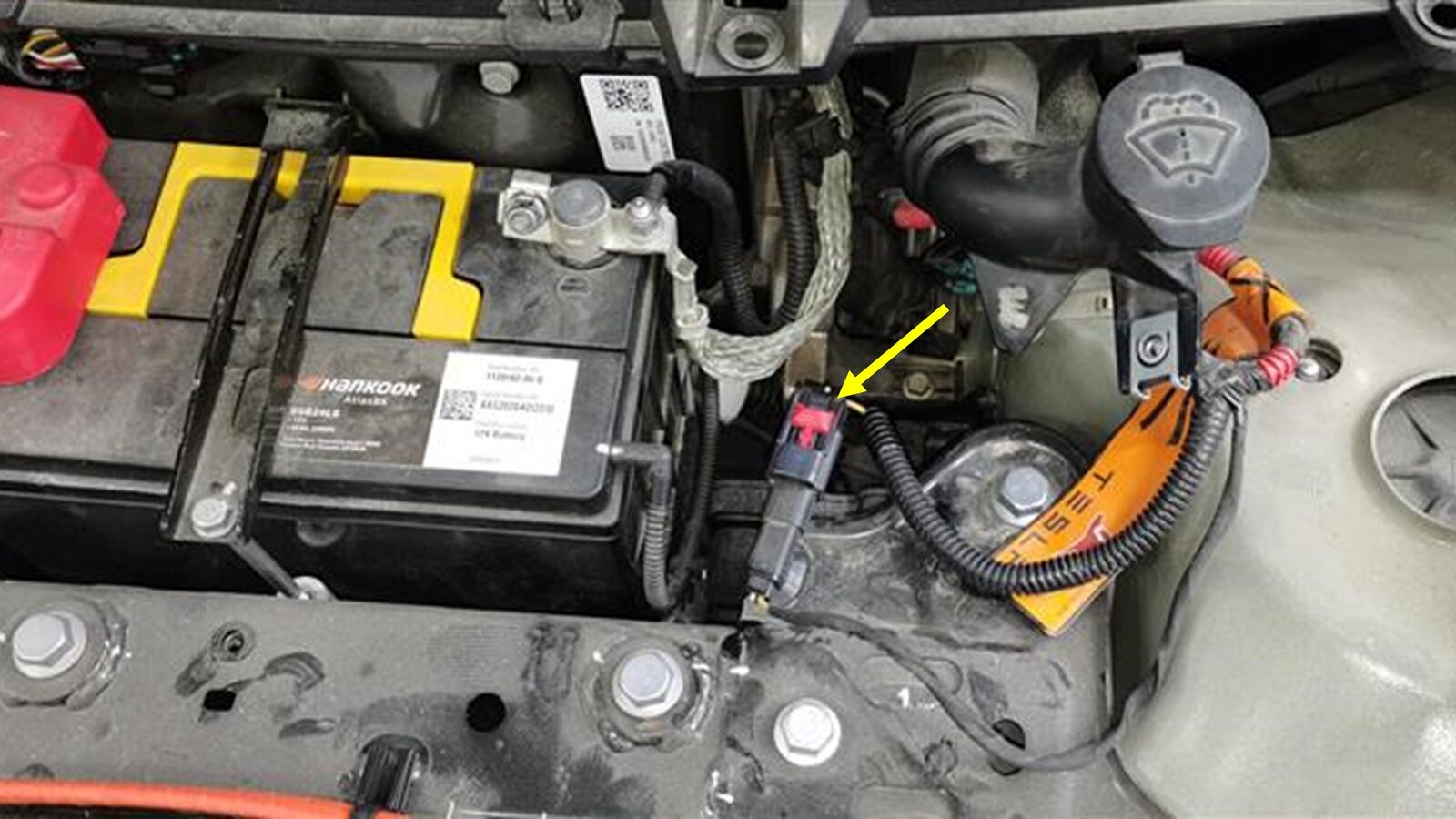
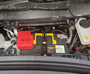
Disconnect 12V negative terminal
Anmerkung1x nut, 10mm, 6 Nm, Ensure vehicle is in park, climate control system is off, and vehicle is not charging before disconnecting 12V

-
Disconnect first responder loop
Anmerkung1x connector, Release locking tab
-
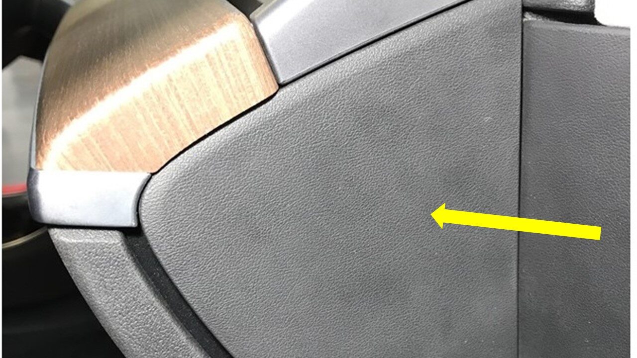
Remove LH IP end cap
Anmerkung3x clips

-
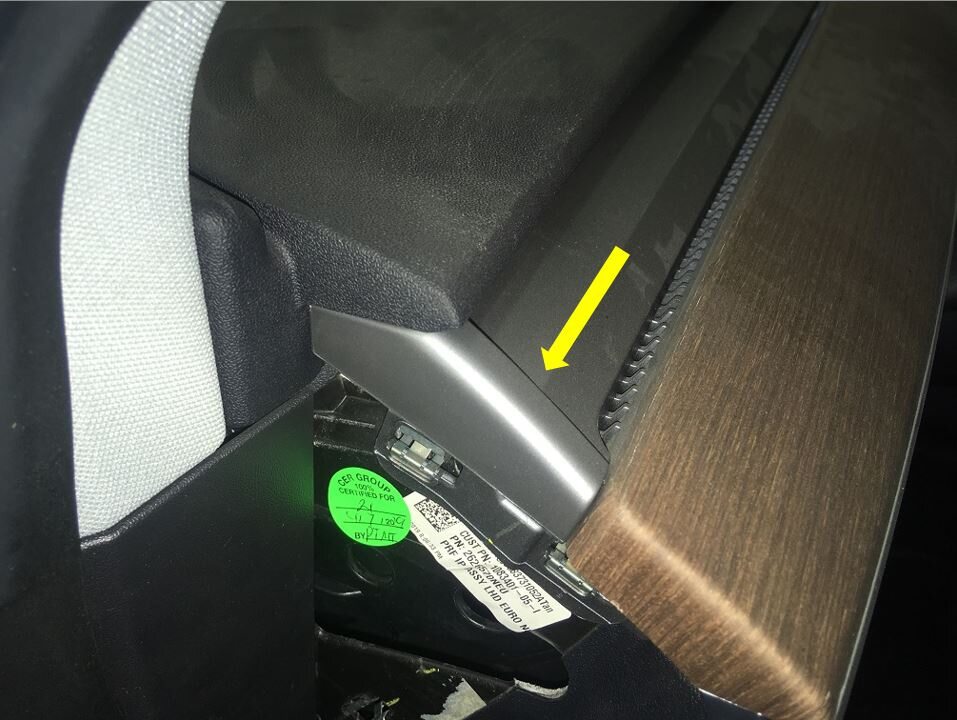
Remove LH air wave bezel cap from main
decor assembly
Anmerkung2x clips, Newer vehicles are equipped with solid bezel.

-
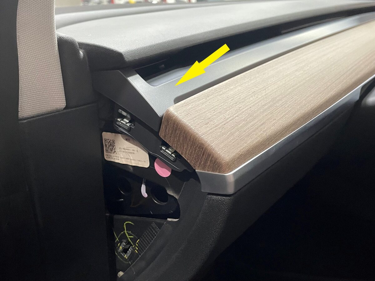
Remove RH IP end cap
Anmerkung3x clips

-
Remove RH air wave bezel cap from main
decor assembly
Anmerkung2x clips, Newer vehicles are equipped with solid bezel.
-
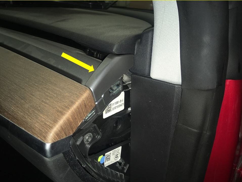
Remove main decor assembly
Anmerkung15x clips, Entire decor does not need to come off for glove box removal, If you lift RH side of decor then you will have access to 3x torx screws securing top of glove box, Replace securing clips as needed


-
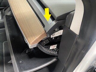
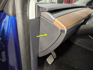
Release RH footwell assembly from
IP
Anmerkung4x push clips

-
Remove RH footwell assembly
Anmerkung2x connectors

-
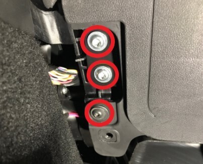
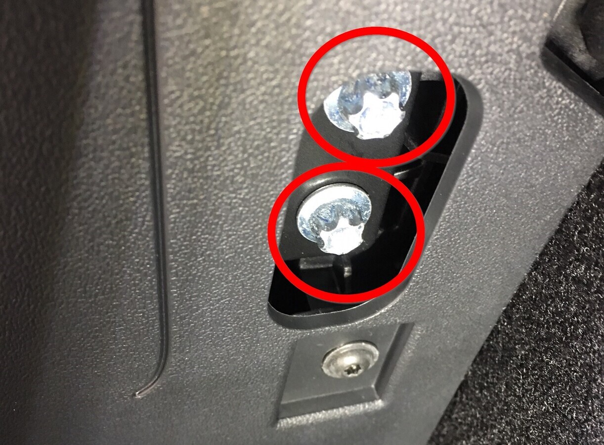
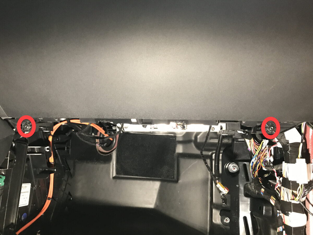
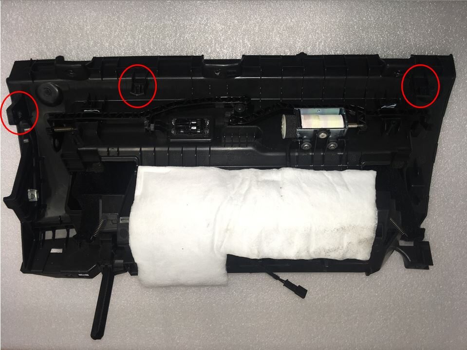
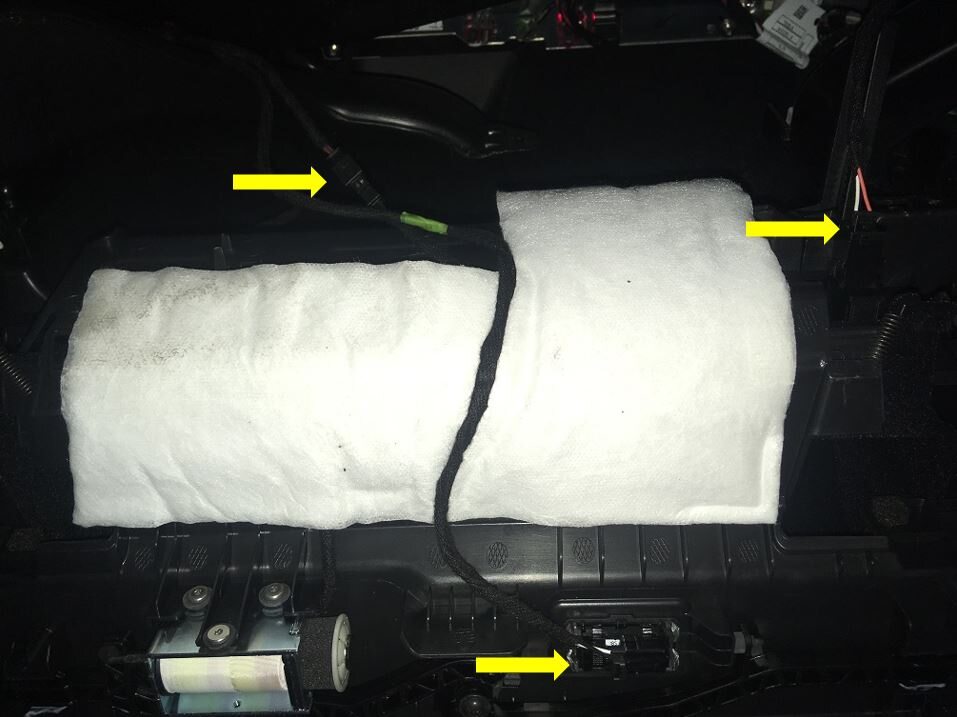
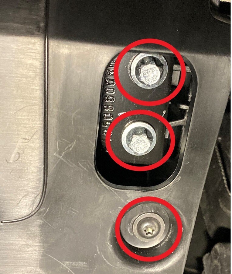
Remove bolts securing passenger knee
air bag onto vehicle
Anmerkung4x patch bolts, T30, 8 Nm, Discard after removal, 2x screws, T20, 2 Nm, 1x push clip, Newer vehicles have 4x E10 patch bolts

-
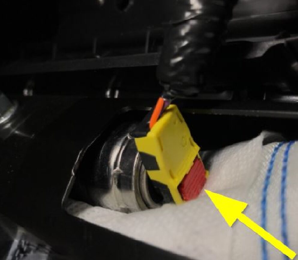
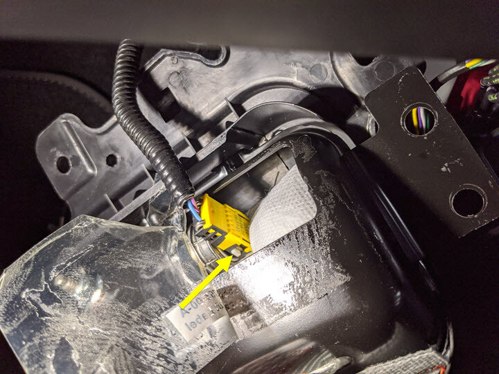
Remove passenger knee air bag from
vehicle
Anmerkung1x connector, Release locking tab, Connector release may vary

-
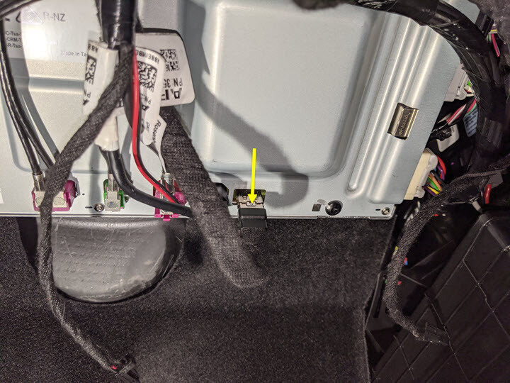
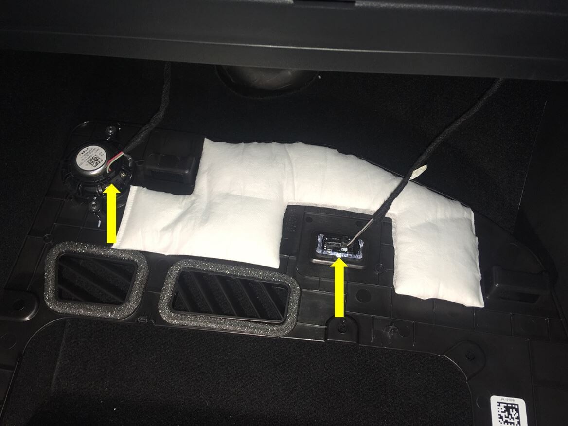
Disconnect glove box USB cable from
car computer
Anmerkung1x connector, Depress latch on top of USB cable to release internal latches, then release from car computer
-
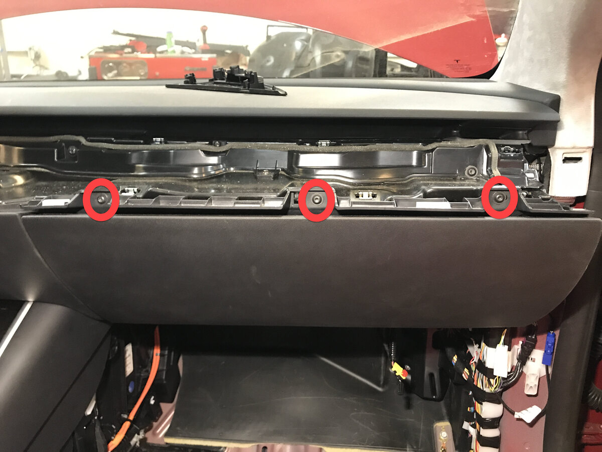
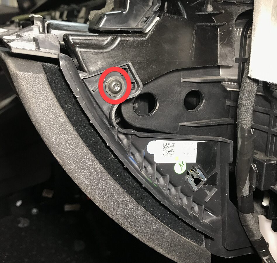
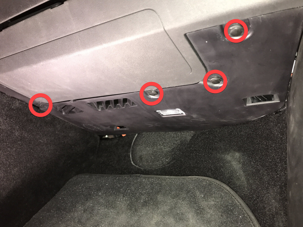
Remove screws securing glove box
assembly to IP carrier
Anmerkung6x screws, T20, 2.3 Nm


-
Remove glove box from IP carrier
Anmerkung3x clips
-
Disconnect glove box assembly
connectors
Anmerkung3x electrical connectors

Montieren
-
Connect glove box assembly
connectors
Anmerkung3x connectors, New puddle lamp harness routing prevent blocking movement of pawls, Make sure harness is routed properly above passenger footwell air duct before connecting


-
Install glove box into IP
carrier
Anmerkung3x clips

-
Install screws securing glove box
assembly to IP carrier
Anmerkung6x screws, T20, 2.3 Nm

-
Connect glove box USB cable to car
computer
Anmerkung1x connector
-
Install passenger knee air bag onto
vehicle
Anmerkung1x connector, Use caution not to damage connector and harness, Support knee air bag while connecting connector

-
Install bolts securing passenger knee
air bag to vehicle
Anmerkung4x patch bolts, E10, 8 Nm, Install new patch bolts, 2x screws, T20, 2 Nm, 1x push clip, If vehicle equipped with T30 bolts update to E10


-
Position RH footwell assembly
Anmerkung2x connectors
-
Install RH footwell assembly onto
IP
Anmerkung4x push clips
-
Install main decor assembly
Anmerkung15x clips, 1x center clip


-
Install RH air wave bezel cap to main
decor assembly
Anmerkung2x clips, Newer vehicles are equipped with solid bezel.


-
Install RH IP end cap
Anmerkung3x clips
-
Install LH air wave bezel cap to main
decor assembly
Anmerkung2x clips, Newer vehicles are equipped with solid bezel.

-
Install LH IP end cap
Anmerkung3x clips
-
Connect first responder loop
Anmerkung1x connector, Engage locking tab, Connect FRL before connecting 12V to avoid damage to car computer
-
Connect 12V negative terminal
Anmerkung1x nut, 10mm, 6 Nm
-
Install rear apron
Anmerkung12x clips


-
Close hood
-
Move RH front seat to original
position

-
Raise LF and RF windows
-
Close both front doors
