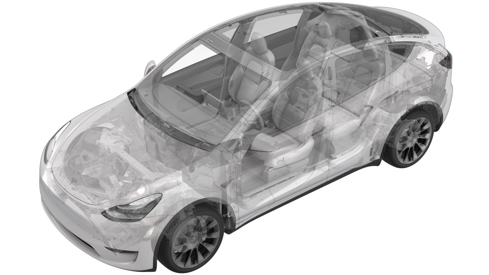
Shunt – HV-Batterie (Nicht Strukturpack)(Ausbauen und Ersetzen)
 16303602 1.14
HINWEIS: Sofern im Verfahren nicht ausdrücklich anders angegeben, spiegeln der obige Korrekturcode und die FRT den gesamten für die Durchführung dieses Verfahrens erforderlichen Aufwand wider, einschließlich der damit verbundenen Verfahren. Schichten Sie keine Korrekturcodes, wenn Sie nicht ausdrücklich dazu aufgefordert werden.
HINWEIS: Unter Richtzeiten erfahren Sie mehr über FRTs und wie sie erstellt werden. Um FRT-Werte rückzumelden, senden Sie bitte eine E-Mail an ServiceManualFeedback@tesla.com.
HINWEIS: Siehe Persönlicher Schutz, um sicherzustellen, dass Sie die richtige persönliche Schutzausrüstung tragen, wenn Sie das folgende Verfahren durchführen. Siehe Maßnahmen zur Ergonomie für sichere und gesunde Arbeitsmethoden.
- 2025-10-22: Updated the routine for different shunt types.
Nur Techniker, die alle erforderlichen Zertifizierungskurse absolviert haben, dürfen dieses Verfahren durchführen. Tesla empfiehlt, dass die Techniker externer Dienstleister entsprechende Schulungen absolvieren, bevor sie dieses Verfahren durchführen. Zu weiteren Informationen über die Anforderungen von Tesla an Techniker oder Beschreibungen der Thematik für Dritte siehe Anforderungen zur HV-Zertifizierung. Beim Umgang mit einem Hochspannungskabel, einer Stromschiene oder eines Hochspannungsanschlusses müssen immer geeignete persönliche Schutzausrüstung (PSA) sowie Isolierhandschuhe mit einer Mindestauslegung von Klasse 0 (1000 V) getragen werden. Weitere Sicherheitsinformationen finden Sie in den Technischen Hinweisen TN-15-92-003, Sorgfaltsregeln beim Umgang mit Hochspannung
.
Technische Daten zum Drehmoment
| Beschreibung | Drehmomentwert | Empfohlene Werkzeuge | Wiederverwenden/Ersetzen | Hinweise |
|---|---|---|---|---|
| Schraube zur Befestigung der Shunt-Baugruppe am HV-Gehäuse |
 9 Nm (6.6 lbs-ft) |
|
Ersetzen |
Ausbauen
- Remove the RH 2nd row seat back. See Rückenlehne – 2. Sitzreihe – RH (Ausbauen und Ersetzen).
- Remove the LH 2nd row seat back. See Rückenlehne – 2. Sitzreihe – LH (Ausbauen und Ersetzen).
- Remove the rear underhood apron. See Unterhaubenschürze – Hinten (Ausbauen und Ersetzen).
- Disconnect 12V power. See 12-V-/Niederspannungsversorgung (Trennen und Verbinden).
- Perform the vehicle electrical isolation procedure. See HV-Abschaltverfahren des Fahrzeugs.
- Remove the ancillary bay cover. See Abdeckung – HV-Gehäuse (Ausbauen und Ersetzen).
- Remove the pyrotechnic battery disconnect. See Pyrotechnische Batteriesicherung (Ausbauen und Ersetzen).
- Remove the shunt insulator. See Isolator – Shunt – HV-Batterie (Ausbauen und Ersetzen).
-
Remove and discard the bolt that attaches the shunt assembly to the ancillary bay.
TIpEs wird empfohlen, die folgenden Werkzeuge zu verwenden:
- Isoliertes Werkzeug:
- Steckschlüssel, 13 mm
- 2-Zoll-Verlängerung
- Isoliertes Werkzeug:
-
Remove the shunt from the vehicle.
Montieren
- Perform a zero adjust of the Hioki resistance meter in preparation to measure resistances later in this procedure. See Widerstandsmessgerät (Nullpunkteinstellung).
-
Write down new shunt bar resistance and part number as printed on the new shunt.
AnmerkungThe resistance is in the range of 20000 to 30000 nano Ohms. For example, "R:25819nΩ" is a resistance of 25819 nano Ohms, so record "25819".AnmerkungSkip this step if installing the original shunt.
- Use an IPA wipe to clean the HV mating surfaces of the shunt, busbar, and the pyrotechnic battery disconnect.
-
Install the shunt to the busbar, and then install and hand-tighten a new bolt to attach the shunt to the busbar.
- Messen Sie die Spannung an den Befestigungspunkten des Pyro-Batterietrennschalters, und montieren Sie den Pyro-Batterietrennschalter. Siehe Pyrotechnische Batteriesicherung (Ausbauen und Ersetzen).
-
Torque the bolt that attaches the shunt assembly to the ancillary bay.
 9 Nm (6.6 lbs-ft)TIpEs wird empfohlen, die folgenden Werkzeuge zu verwenden:
- Isoliertes Werkzeug:
- Steckschlüssel, 13 mm
- 2-Zoll-Verlängerung
- Isoliertes Werkzeug:
- Install the shunt insulator. See Isolator – Shunt – HV-Batterie (Ausbauen und Ersetzen).
-
Use the Hioki resistance meter to measure the resistance of the HV joint between the shunt and the adjacent busbar.
AnmerkungThe maximum acceptable resistance is 0.045 mΩ (45 μΩ). If the resistance is above this value, escalate a Toolbox session, as appropriate.
- Install the ancillary bay cover. See Abdeckung – HV-Gehäuse (Ausbauen und Ersetzen).
- Install the LH 2nd row seat back. See Rückenlehne – 2. Sitzreihe – LH (Ausbauen und Ersetzen).
- Install the RH 2nd row seat back. See Rückenlehne – 2. Sitzreihe – RH (Ausbauen und Ersetzen).
- Install the 2nd row lower seat cushion. See Sitzkissen – Unten – 2. Sitzreihe (Ausbauen und Ersetzen).
- Connect 12V power. See 12-V-/Niederspannungsversorgung (Trennen und Verbinden).
- Skip step 15 through step 19 if installing the original shunt.
- Connect an LV maintainer. See LV-Erhaltungslader (Verbinden und Trennen).
- Connect the laptop with Toolbox 3 to the vehicle.
-
Select and operation, enter the shunt bar resistance value previously recorded in step 2, and select corresponding shunt type based on the Part number. Click Run and allow the routine to complete.
AnmerkungThe unit of the input resistance value is nΩ.AnmerkungShunt types includes Vishay whose part number looks like 2084224-XX-X and Cyntec whose part number looks like 1078835-XX-X or 1588177-XX-X.
- Disconnect the laptop from the vehicle.
- Disconnect an LV maintainer. See LV-Erhaltungslader (Verbinden und Trennen).
- Install the rear underhood apron. See Unterhaubenschürze – Hinten (Ausbauen und Ersetzen).