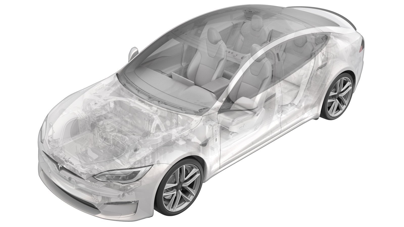
Coupleur hydraulique - unité d'entraînement arrière (Plaid) (retrait et remplacement)
 Code de correction
40010012 2.82
REMARQUE : À moins d’indications explicites contraires dans la procédure, le code de correction et le temps forfaitaire ci-dessus représentent tout le travail à être fait pour cette procédure, notamment les procédures connexes. N’appliquez pas plusieurs codes de correction à la fois, à moins qu’il vous soit explicitement indiqué de le faire.
REMARQUE : Consultez Temps forfaitaires pour en apprendre plus à propos des temps forfaitaires et de leur création. Vous pouvez transmettre par courriel vos commentaires relatifs aux valeurs des temps forfaitaires à ServiceManualFeedback@tesla.com.
NOTE : Consultez Protection individuelle pour veiller à porter l’ÉPI approprié lorsque vous effectuez la procédure ci-dessous.
Retirer
- Retirez l’unité d’entraînement arrière. Voir Unité d'entraînement – arrière (Plaid) (retrait et installation),
- Branchez un ordinateur portable doté de Toolbox au véhicule. Voir Toolbox 3.0 (connecter et déconnecter),
- Relâchez le frein de stationnement électronique. Voir Étrier de frein de stationnement – dégagement,
- Débranchez l’ordinateur portable doté de Toolbox du véhicule. Voir Toolbox 3.0 (connecter et déconnecter),
- Retirez le tablier arrière situé sous le capot. Voir Tablier sous le capot - arrière (retirez et remplacez),
- Déconnectez l’alimentation basse tension. Voir Alimentation 12 BT (déconnecter et connecter).
-
Réglez le multimètre haute tension sur la tension c.c., touchez légèrement les sondes sur les contacts du connecteur de batterie auxiliaire et vérifiez que le multimètre affiche une tension.
RemarqueLa tension de la batterie est généralement comprise entre 14,5 et 15,5 V.
- Retirez les roues arrière. Voir Ensemble de roue (retrait et installation),
- Retirez le panneau de protection aérodynamique intermédiaire. Voir Panneau – bouclier aérodynamique – arrière (retrait et remplacement),
- Effectuez la procédure de désactivation HT du véhicule. Voir Procédure de désactivation HT du véhicule.
- Retirez les couvre-gants en cuir et les gants isolants HT.
- Retirez le diffuseur de carénage arrière. ConsultezDiffuseur- carénage arrière (retirez et remplacez).
- Retirez les doublures de passage de roue arrière gauche et droite. Voir Doublure de passage de roue – arrière – côté gauche (Retirer et remplacer),
- Retirez l’ensemble du cadre auxiliaire arrière. Voir Ensemble de châssis auxiliaire – arrière (Plaid) (retrait et installation),
- Retirez l’ensemble du châssis auxiliaire de sous le véhicule.
- Positionnez le collecteur de liquide sous le sous-châssis et l'ensemble de fixation.
-
Relâchez le collier de serrage du tuyau, relâchez le tuyau d'alimentation du groupe motopropulseur de l'inverseur arrière gauche, puis branchez les tuyaux.
RemarquePlacez des serviettes en dessous pour attraper tout liquide de refroidissement.
-
Retirez et mettez au rebut le boulon qui fixe le raccord de liquide de l’unité d’entraînement arrière à l’unité d’entraînement arrière, puis retirez le raccord de l’onduleur.
 6 Nm (4.4 lbs-ft)TIpNous recommandons l’utilisation des outils suivants :
- Douille Torx T25
Installer
-
Lubrifiez le joint torique du coupleur hydraulique droit avec du liquide de refroidissement.
ATTENTIONN’installez jamais le coupleur hydraulique avec un joint torique sec.
-
Installez le coupleur hydraulique de l'unité d'entraînement arrière dans l'unité d'entraînement arrière, puis installez un nouveau boulon qui fixe l'accouplement à l'onduleur.
 6 Nm (4.4 lbs-ft)TIpNous recommandons l’utilisation des outils suivants :
- Douille Torx T25
-
Retirez les bouchons de tuyau, raccordez le tuyau d’alimentation du groupe motopropulseur à l'onduleur arrière gauche, puis installez l’attache du tuyau.
RemarqueEffectuez un test de solidité en poussant, tirant et poussant de nouveau pour vous assurer que le tuyau est solidement en place.
- Retirez le collecteur de liquide de sous le châssis auxiliaire et l’ensemble de fixation.
- Installez l’ensemble cadre auxiliaire arrière. Voir Ensemble de châssis auxiliaire – arrière (Plaid) (retrait et installation),