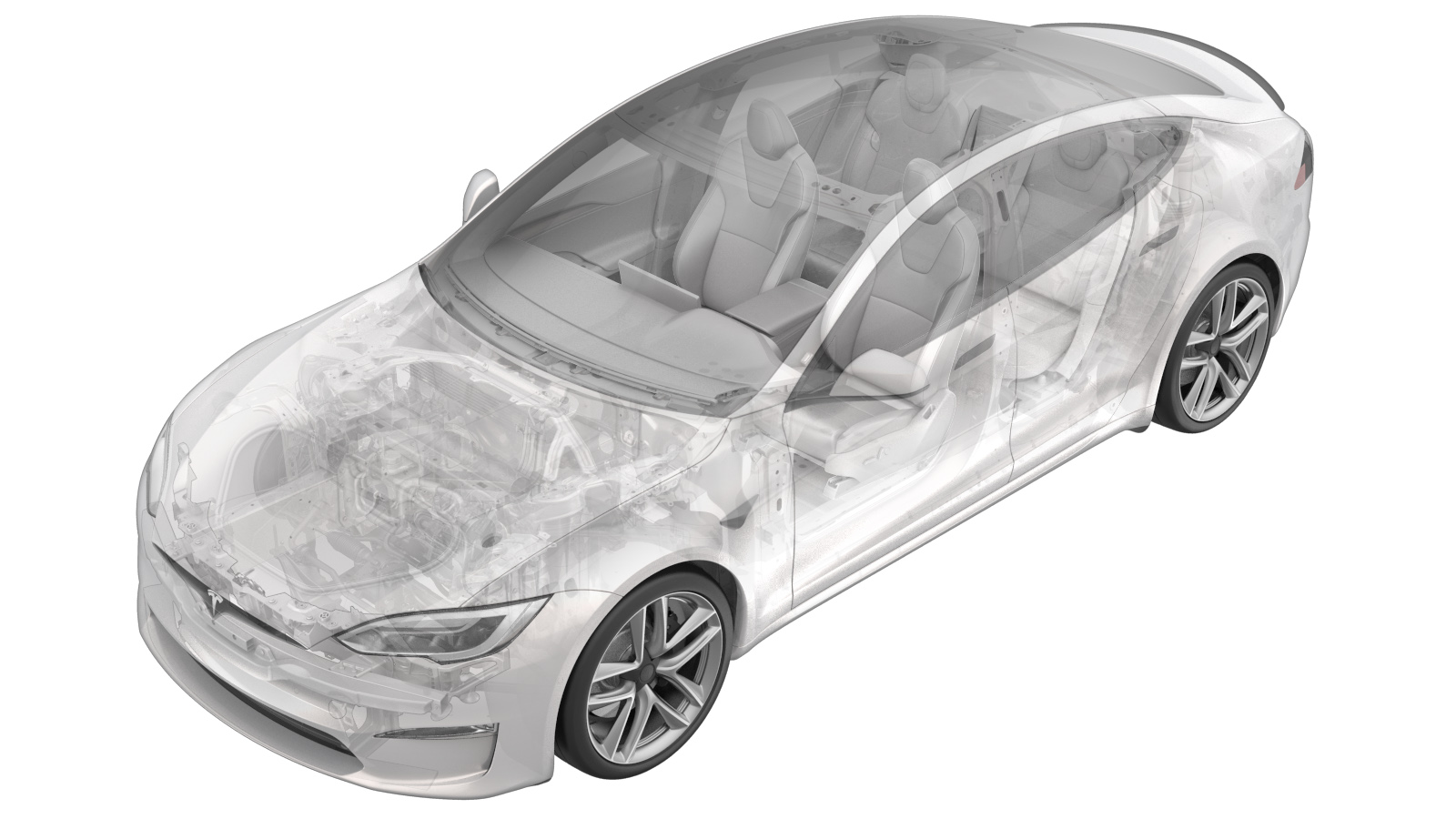
Module - commande de la carrosserie - sécurité (retirez et remplacez)
 Code de correction
17454002 0.48
REMARQUE : À moins d’indications explicites contraires dans la procédure, le code de correction et le temps forfaitaire ci-dessus représentent tout le travail à être fait pour cette procédure, notamment les procédures connexes. N’appliquez pas plusieurs codes de correction à la fois, à moins qu’il vous soit explicitement indiqué de le faire.
REMARQUE : Consultez Temps forfaitaires pour en apprendre plus à propos des temps forfaitaires et de leur création. Vous pouvez transmettre par courriel vos commentaires relatifs aux valeurs des temps forfaitaires à ServiceManualFeedback@tesla.com.
NOTE : Consultez Protection individuelle pour veiller à porter l’ÉPI approprié lorsque vous effectuez la procédure ci-dessous.
- 2025-03-07: Updated post-replacement routines.
- 2023-11-20: Updated security controller configuration steps.
- 2023-10-24: Updated post-replacement Toolbox routines.
- 2023-07-21: Added Note about security-related toolbox actions.
Retirer
- Remove the LH and RH middle A-pillar trim. See Garniture - montant avant - milieu - gauche (retirez et remplacez).
- Remove the LH and RH Instrument Panel end caps. See Capuchons d’extrémité - tableau de bord - gauche (retirez et remplacez).
- Remove the LH and RH upper A-pillar trim. See Garniture - montant avant - supérieure - gauche (retirez et remplacez).
- Remove the LH and RH sun visor. See Pare-soleil - gauche (retirez et remplacez).
- Power off the vehicle using the center display. Touch
- Remove the rear underhood apron. See Tablier sous le capot - arrière (retirez et remplacez).
- Disconnect the LV battery. See Alimentation 12 BT (déconnecter et connecter).
-
Remove the rear view mirror. See Rétroviseur - vue arrière (retirez et remplacez).
RemarqueRotate mirror to release
- Remove the upper quad camera cover. See .
-
Release the clips (x5) that attach the headliner to the front of the vehicle.
-
Disconnect the electrical harness from the security controller.
-
Remove the bolt that attaches the security controller to the vehicle.
Remarque1x bolt, T30RemarqueThe bolt is captive inside controller housing and cannot be removed.
-
Release the clip and guide pin that attach the security controller to the vehicle, and then remove the security controller from the vehicle.
Installer
-
Position the security controller to body using the clip and guide pin.
-
Install the bolt that attaches the security controller to the vehicle.
Remarque1x bolt, T30, 9 NmRemarqueThe bolt is captive inside controller housing and cannot be removed.
-
Connect the electrical harness to the security controller.
-
Install the clips (x5) that attach the headliner to the vehicle.
- Install the upper quad camera cover. See .
- Install the rear view mirror. See Rétroviseur - vue arrière (retirez et remplacez).
- Connect the LV battery. See Alimentation 12 BT (déconnecter et connecter).
- Install the rear underhood apron. See Tablier sous le capot - arrière (retirez et remplacez).
- Install the LH and RH sun visor. See Pare-soleil - gauche (retirez et remplacez).
- Install the LH and RH upper A-pillar trim. See Garniture - montant avant - supérieure - gauche (retirez et remplacez).
- Install the LH and RH Instrument Panel end caps. See Capuchons d’extrémité - tableau de bord - gauche (retirez et remplacez).
- Install the LH and RH middle A-pillar trim. See Garniture - montant avant - milieu - gauche (retirez et remplacez).
- Perform a service redeploy. See Réinstallation du micrologiciel - Toolbox.
- Exécutez la routine suivante au moyen du mode Entretien ou de Toolbox (consultez 0005 – Modes d’entretien) : PROC_VCSEC_X_POST-REPLACEMENT-PROCEDUREvia Toolbox: (link)via Service Mode: Low Voltage ➜ Keys ➜ VCSEC Post Replacementvia Service Mode Plus: LowVoltage ➜ VCSEC Post Replacement ➜ VCSEC Post Replacement Procedure
- Exécutez la routine suivante au moyen du mode Entretien ou de Toolbox (consultez 0005 – Modes d’entretien) : PROC_VCSEC_C_PAIR-NFC-CARD-V2via Toolbox: (link)via Service Mode: Low Voltage ➜ Keys ➜ Pair Key
-
Place the NFC card(s) on the console phone dock.
- Input the number of keys to be paired to the vehicle, click Run Network, and allow the routine to complete.
- Check the function of the programmed NFC keys.
- Inform the customer that the new security body controller will not recognize any previously paired phone key. The customer must delete and re-pair their phone key to the vehicle, if they were previously using this feature. Instructions are available in the Owners Manual, and at the DIY web pages.