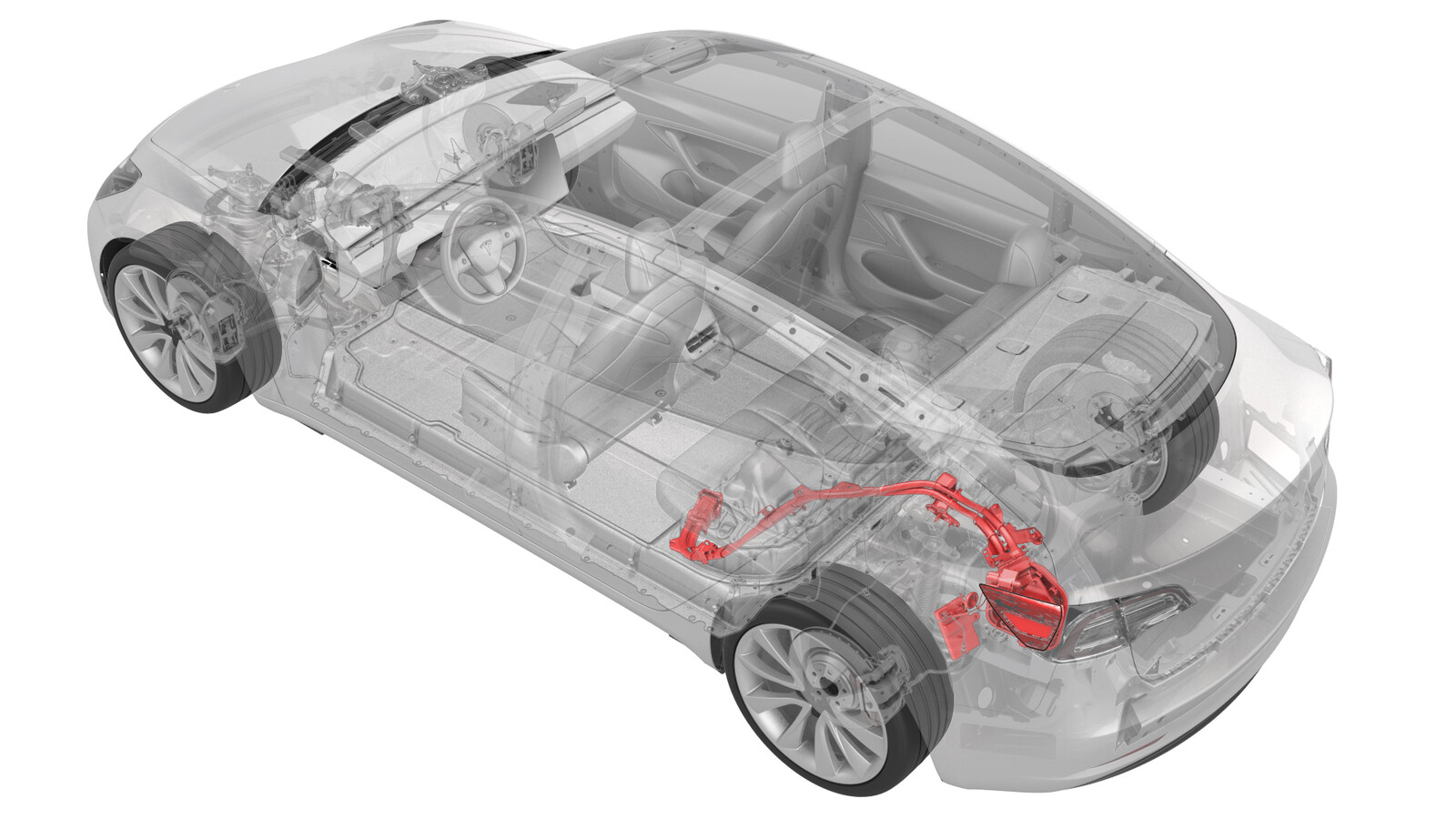
Ladeanschluss und Sammelschiene zu HV-Batterie (einphasig) (Nachrüsten)
 Korrekturcode
44013106 1.98
HINWEIS: Sofern im Verfahren nicht ausdrücklich anders angegeben, spiegeln der obige Korrekturcode und die FRT den gesamten für die Durchführung dieses Verfahrens erforderlichen Aufwand wider, einschließlich der damit verbundenen Verfahren. Schichten Sie keine Korrekturcodes, wenn Sie nicht ausdrücklich dazu aufgefordert werden.
HINWEIS: Unter Richtzeiten erfahren Sie mehr über FRTs und wie sie erstellt werden. Um FRT-Werte rückzumelden, senden Sie bitte eine E-Mail an ServiceManualFeedback@tesla.com.
HINWEIS: Siehe Persönlicher Schutz, um sicherzustellen, dass Sie die richtige persönliche Schutzausrüstung tragen, wenn Sie das folgende Verfahren durchführen. Siehe Maßnahmen zur Ergonomie für sichere und gesunde Arbeitsmethoden.
- 2023-05-24: Replaced the vehicle electrical isolation procedure with the charge port voltage check procedure.
Nur Techniker, die alle erforderlichen Zertifizierungskurse absolviert haben, dürfen dieses Verfahren durchführen. Tesla empfiehlt, dass die Techniker externer Dienstleister entsprechende Schulungen absolvieren, bevor sie dieses Verfahren durchführen. Zu weiteren Informationen über die Anforderungen von Tesla an Techniker oder Beschreibungen der Thematik für Dritte siehe Anforderungen zur HV-Zertifizierung. Beim Umgang mit einem Hochspannungskabel, einer Stromschiene oder eines Hochspannungsanschlusses müssen immer geeignete persönliche Schutzausrüstung (PSA) sowie Isolierhandschuhe mit einer Mindestauslegung von Klasse 0 (1000 V) getragen werden. Weitere Sicherheitsinformationen finden Sie in den Technischen Hinweisen TN-15-92-003, Sorgfaltsregeln beim Umgang mit Hochspannung
.
Legen Sie vor allen Arbeiten an hochspannungsführenden Anlagen jeglichen Körperschmuck ab (Uhr, Armbänder, Ringe, Halsketten, Ohrringe, Plaketten, Piercings usw.), und leeren Sie Ihre Taschen (Schlüssel, Münzen, Stifte, Werkzeug, Befestigungsmittel usw.).
Proper Personal Protective Equipment (PPE) is required to perform this procedure:
- High Voltage (HV) insulating gloves
- Leather glove protectors
- High voltage glove tester
- Safety glasses
- Electrical hazard rated safety shoes
A glove inflator is the only recommended way to test HV gloves. Both HV gloves must pass testing before beginning this procedure. If either glove does not pass the air check, discard the pair.
Make sure that the HV gloves are not expired. HV gloves can be used up to 12 months after the testing date printed on the glove, but only 6 months after first use even if the gloves are still within the 12-month period.
Ausbauen
- Open all doors and lower all windows.
- Move both front seats forward.
- Open the trunk and the charge port door.
- Perform the charge port voltage check procedure. See Ladeanschluss-Spannungsprüfung.
- Remove the charge port to HV battery harness. See Charge Port and HV Harness Assembly (NACS) (Remove and Replace).
-
Remove the bolt that attaches the
charge port ECU to the body.
 5.5 Nm (4.1 lbs-ft)
 -
Slide the charge port ECU to the right
to release the tabs (x2) that attach the ECU to the body, and then remove the old ECU
from the vehicle.
- Remove the ancillary bay cover. See Abdeckung – HV-Gehäuse (Ausbauen und Ersetzen).
- Remove the old input assembly and charge port. See DC-Eingangsbaugruppe – HV-Batterie (Kabelbaumausführung) (Ausbauen und Ersetzen).
Montieren
- Install the Busbar type DC input assembly, but do not connect 12V at this stage. See DC-Eingangsbaugruppe – HV-Batterie (Sammelschienenausführung) (Ausbauen und Ersetzen)
- Install the ancillary bay cover. See Abdeckung – HV-Gehäuse (Ausbauen und Ersetzen).
-
Slide the new Busbar type charge port
ECU onto the bracket that attaches the ECU to the body.
-
Install the bolt that attaches the
charge port ECU to the body.
 5.5 Nm (4.1 lbs-ft)
 -
Install the new Busbar type charge
port. See Charge Port (Busbar Type) (NACS) (Remove and Replace).
AnmerkungThe above procedure uses existing ECU and charge port connectors in the main body harness. For this retrofit procedure, use the retrofit harness to connect the ECU and charge port electrical connections.
- Install the charge port to HV battery busbar. See Sammelschienen – Ladeanschluss zu HV-Batterie (NACS) (Ausbauen und Ersetzen).
- Reinstall the vehicle firmware. See Neuinstallation der Software – Touchscreen.
-
Verify the charging system is
operating correctly.
AnmerkungUse the customer's charging equipment if available. Ensure all the charging adapters are present.
- Move both front seats to their original positions.
- Raise all windows and close all doors.