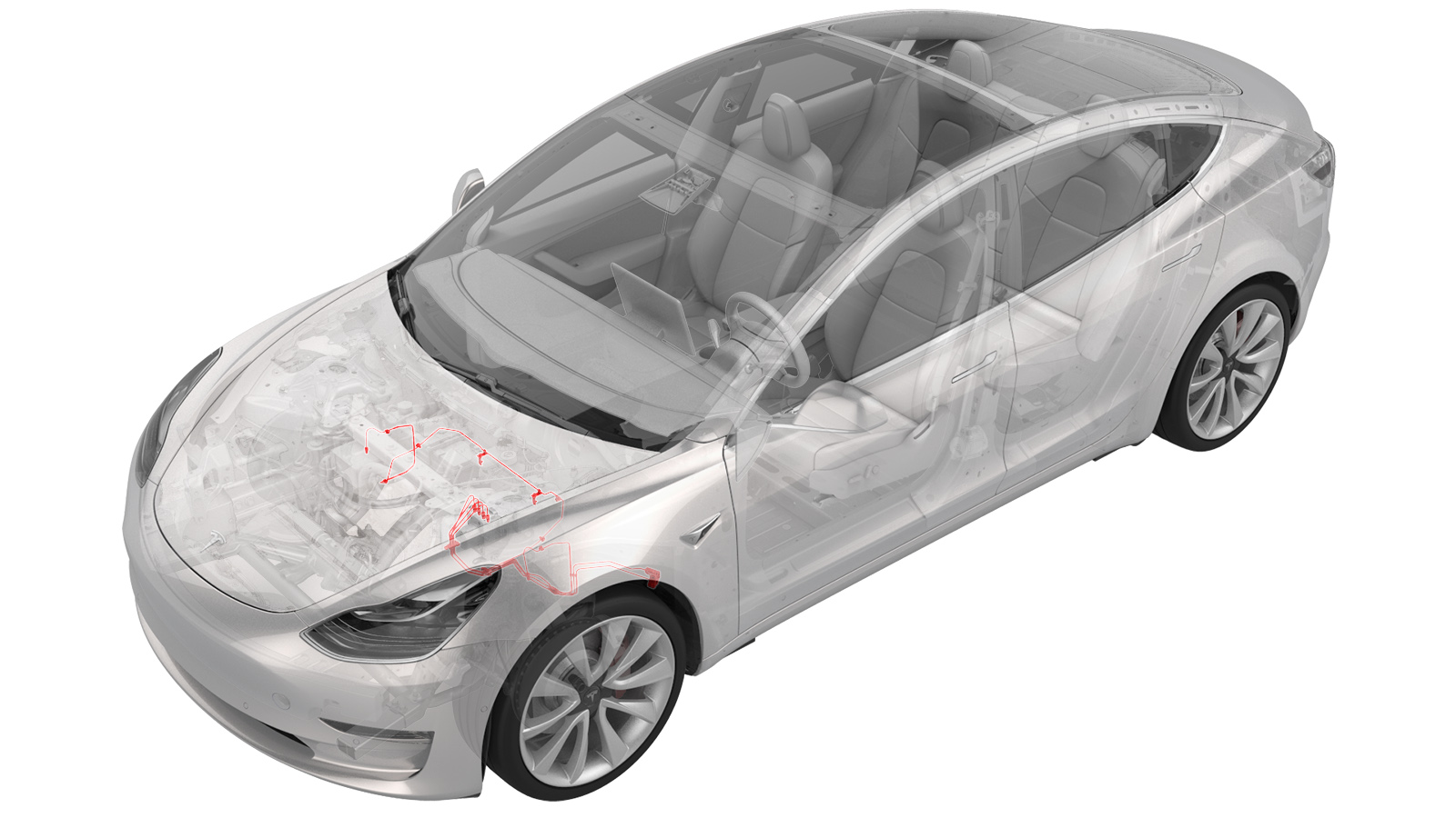
Bremsleitungen – 4-Rohr-Bündel – ABS zu den Rädern (Dual Motor) (Ausbauen und Ersetzen)
 Korrekturcode
330339524.62
HINWEIS: Sofern im Verfahren nicht ausdrücklich anders angegeben, spiegeln der obige Korrekturcode und die FRT den gesamten für die Durchführung dieses Verfahrens erforderlichen Aufwand wider, einschließlich der damit verbundenen Verfahren. Schichten Sie keine Korrekturcodes, wenn Sie nicht ausdrücklich dazu aufgefordert werden.
HINWEIS: Unter Richtzeiten erfahren Sie mehr über FRTs und wie sie erstellt werden. Um FRT-Werte rückzumelden, senden Sie bitte eine E-Mail an ServiceManualFeedback@tesla.com.
HINWEIS: Siehe Persönlicher Schutz, um sicherzustellen, dass Sie die richtige persönliche Schutzausrüstung tragen, wenn Sie das folgende Verfahren durchführen. Siehe Maßnahmen zur Ergonomie für sichere und gesunde Arbeitsmethoden.
Bremsflüssigkeit löst Lack auf. Halten Sie saubere Handtücher und reichlich Wasser bereit, um verschüttete Bremsflüssigkeit von lackierten Flächen zu entfernen.
Entsorgen Sie gebrauchte Bremsflüssigkeit gemäß den örtlichen Umweltschutzvorschriften.
- Remove the front subframe. See Hilfsrahmenbaugruppe – Vorn (Dual Motor) (Ausbauen und Ersetzen).
- Remove the 12V battery bracket. See Halterung – 12-V-Batterie (Dual Motor) (Ausbauen und Ersetzen).
-
Remove the bolts (x2) that attach the ground leads (G098 and G099) to the LH side of the body.
AnmerkungDiscard thread-cutting tri-lobular bolts after removal. If equipped with new bolts (1447438-00-A), the bolts can be reused.
-
Release the white harness clip from the body.
-
Release the black harness clip from the body.
-
Remove the front harness clip from the LH frame rail area.
-
Disconnect the ground connector (G011) from the LH frame rail area.
-
Move the LH side of the front harness aside for access.
-
Disconnect the ABS modulator connector.
AnmerkungDisengage locking tab and pull up on the connector to release.
-
Release the front harness clips (x2) at the LH frame rail area.
- Platzieren Sie den Ölauffangbehälter unter der ABS-Einheit.
-
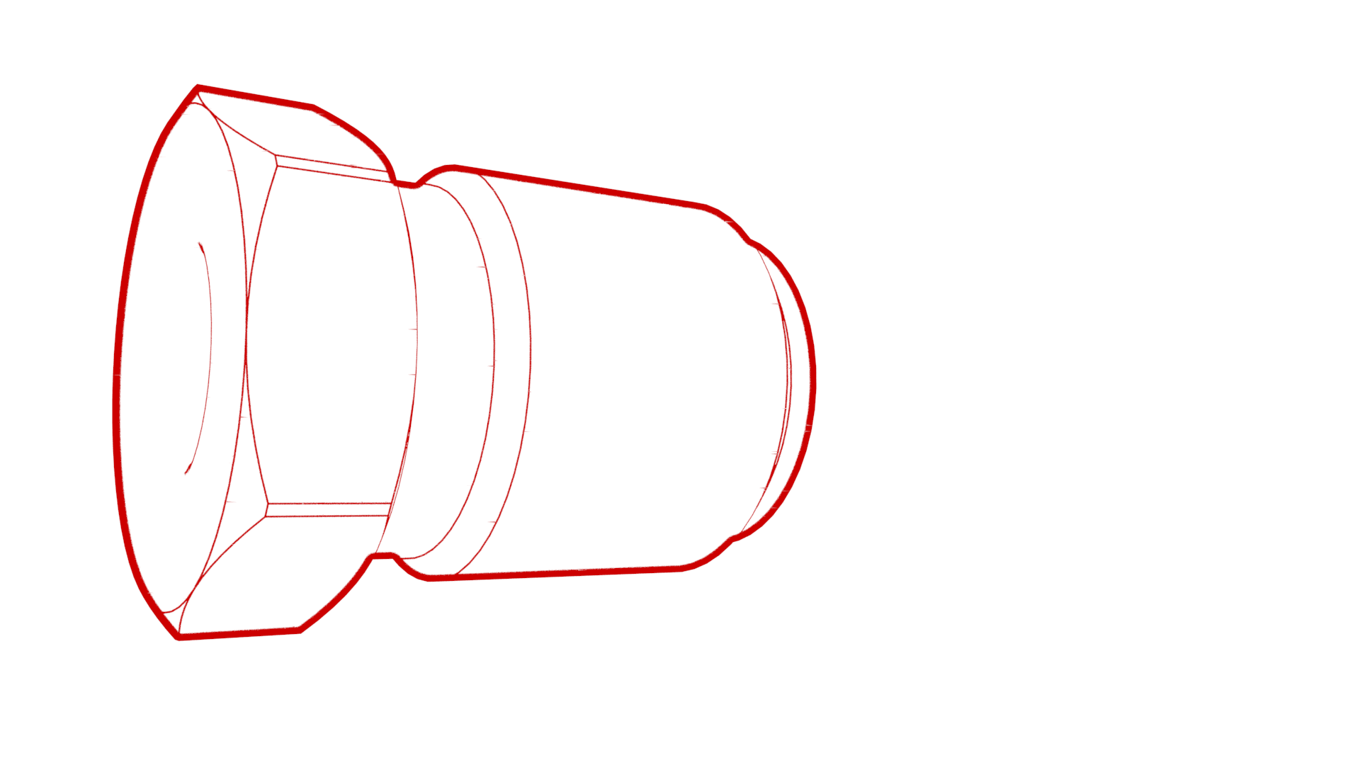
Entfernen Sie die Überwurfmuttern der Bremsleitung von der ABS-Einheit, und lassen Sie die Flüssigkeit ablaufen.
-
Remove the front brake line bundle clip at the LH front rail area.
-
Remove the RH front brake line from the front brake line bundle clip at the LH front rail area.
- Remove the oil drain container from underneath the vehicle.
- Partially raise the vehicle.
-
Remove the thermal beam hose clips (x2) from the body.
- Platzieren Sie den Ölauffangbehälter unter dem vorderen Leitungsanschlussblock.
-
Entfernen Sie die Überwurfmuttern der Bremsleitung vom Anschlussblock, und lassen Sie die Flüssigkeit ablaufen.
-
Remove the black clip from the LH front junction block.
-
Release the brake lines from the LH front junction block.
- Platzieren Sie den Ölauffangbehälter unter dem Bremsschlauch vorne LH.
-
Entfernen Sie die Überwurfmutter der Bremsleitung an der Halterung für den Druckstufenschlauch vom Bremsschlauch, und lassen Sie die Flüssigkeit ablaufen.
-
Remove the LH front brake line clip from the body.
- Platzieren Sie den Ölauffangbehälter unter dem Bremsschlauch vorne RH.
-
Entfernen Sie die Überwurfmutter der Bremsleitung an der Halterung für den Druckstufenschlauch vom Bremsschlauch, und lassen Sie die Flüssigkeit ablaufen.
-
Remove the RH front brake line clips (x2) from the body.
- Fully raise the vehicle.
-
Release the coolant hose clip on the LH fender.
-
Remove the front brake line bundle clip from the LH body rail area.
-
Remove the LH front side 3 bundle brake lines from the vehicle.
AnmerkungRoute the front brake line bundle out of steering column area, then route it through LH front wheel liner and front subframe area.
-
Release the clips (x3) that attach the 12V harness to the body.
-
Release the clips (x7) that attach the HV cables to the body.
-
Release the clips (x2) that attach the coolant manifold line from the body.
-
Release the clips (x4) that attach the coolant hoses to the body.
-
Release the clip that attaches the coolant hose to the RH side of the body.
-
Remove the clips (x5) that attach the RH front brake line to the body.
-
Remove the RH front brake line from the vehicle.
AnmerkungRoute the brake line out of steering column area, then move it towards the RH side, and the remove it out between the front subframe area.
Montieren
- Remove the RH front brake line from the new front 4 tube brake bundle.
-
Position the RH front brake line to vehicle for installation.
AnmerkungRoute the RH front brake line through the front subframe area out toward the RH front wheel liner area, then route it to LH frame rail area.
-
Install the clips (x5) that attach the RH front brake line to the body.
-
Install the clip that attaches the RH side coolant hose to the body.
-
Install the clips (x4) that attach the coolant hoses to the body.
-
Install the clips (x2) that attach the coolant manifold line to the body.
-
Install the clips (x7) that attach the HV cables to the body.
-
Install the clips (x3) that attach the 12V harness to the body.
-
Install the left side 3 tube bundle to the vehicle.
AnmerkungRoute the brake line bundle through the LH front wheel liner and front subframe area, then route it to LH frame rail area.
-
Install the clip that attaches the coolant hose to the LH fender.
-
Install the clip that attaches the front brake line bundle to LH body rail area.
- Partially lower the vehicle.
-
Install the RH front brake line into the brake hose at the jounce hose bracket, and then use a crowfoot extension to install the brake line tube nut into the brake hose.
 16 Nm (11.8 lbs-ft)
 -
Install the RH front brake line clips (2) to the body.
-
Setzen Sie die Bremsleitung an der Halterung für den Druckstufenschlauch in den Bremsschlauch ein, und verwenden Sie eine Krähenfußverlängerung, um die Überwurfmutter der Bremsleitung am Bremsschlauch zu montieren.
 16 Nm (11.8 lbs-ft)
 -
Install the clip that attaches the LH front brake line clip to body
Anmerkung1x clip
-
Install the brake lines into the LH front junction block.
-
Install the clip that secures the brake lines at the LH front junction block.
-
Use a crowfoot extension to install the brake line tube nuts into the junction block.
 16 Nm (11.8 lbs-ft)
 -
Install the thermal beam hose clips (x2) to the body.
- Lower the vehicle.
-
Install the RH front brake line to front brake line bundle clip at the LH front rail area.
-
Install the front brake line bundle clip at the LH front rail area.
-
Install the master cylinder brake lines to the 4 tube bundle clip.
-
Setzen Sie die Bremsleitungen in die ABS-Einheit ein, und verwenden Sie eine Krähenfußverlängerung, um die Überwurfmuttern der Bremsleitung an der ABS-Einheit zu montieren.
 16 Nm (11.8 lbs-ft)
 -
Re-position the LH side of the front harness to the LH frame rail for installation.
-
Install the front harness clips (x2) at the LH frame rail area.
-
Connect the LH frame rail ground connector (G011).
-
Install the front harness clip to the LH frame rail area.
-
Install the white harness clip to the left front fender.
-
Install the black harness clip to the left front fender.
-
Install the bolts (x2) that attach the grounds leads (G098 and G099) to the body (torque 10 Nm).
AnmerkungInstall new bolts if thread-cutting tri-lobular bolts were installed previously. Hand-start bolts at least 6 rotations before applying torque to avoid damaging the weld nut.
-
Install the ABS modulator connector
AnmerkungGently push connector downward, then engage locking tab
- Reinstall the 12V battery bracket. See Halterung – 12-V-Batterie (Dual Motor) (Ausbauen und Ersetzen).
- Install the 12V battery into the vehicle. See 12-V-/LV-Batterie (Ausbauen und Ersetzen).
- Install the front subframe. See Hilfsrahmenbaugruppe – Vorn (Dual Motor) (Ausbauen und Ersetzen).
- Connect 12V power. See 12-V-/Niederspannungsversorgung (Trennen und Verbinden).
- Remove the HVAC plenum outer duct. See Luftsammler –-Einlass – HLK (Ausbauen und Ersetzen).
- Perform a coolant air purge. See Kühlsystem (Teilweise füllen und Entlüften).
- Bleed the brakes. See Bremsflüssigkeit entlüften/spülen.
- Install the underhood storage unit. See Frontstauraum (Ausbauen und Ersetzen).
- Install the HVAC plenum outer duct. See Luftsammler –-Einlass – HLK (Ausbauen und Ersetzen).
- Install the rear underhood apron. See Unterhaubenschürze – Hinten (Ausbauen und Ersetzen).
- Install the front aero shield. See Verkleidung – Windabweiser – Vorne (Ausbauen und Ersetzen).
- Install the LH and RH wheel liner. See Radhausverkleidung – Vorne – LH (Ausbauen und Ersetzen).
- Install all wheels. See Radbaugruppe (Aus- und Einbauen).
- Torque the LH and RH front halfshaft nuts to 300 Nm.
- Perform a 4-wheel alignment check. See Achsvermessung.