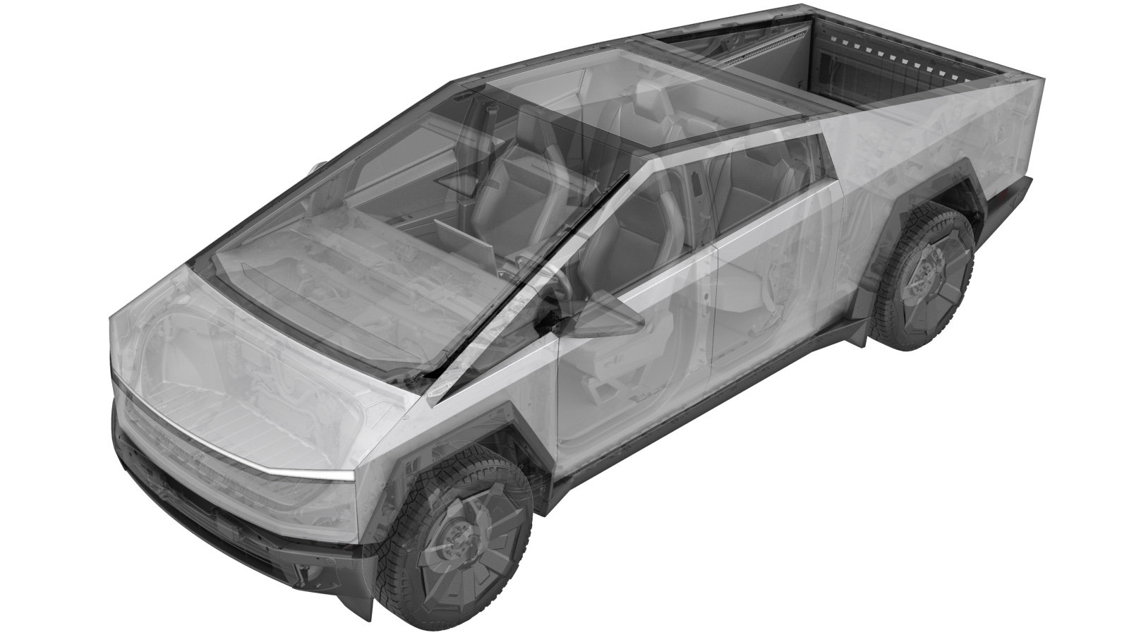
Tire Rotation and Balance with Automatic TPMS Learn (Rebalance)
 Código de corrección
34020505, 34020305
FRT 0.750.75
NOTA: Salvo que se indique lo contrario explícitamente en el procedimiento, el código de corrección anterior y el FRT reflejan todo el trabajo necesario para realizar este procedimiento, incluidos los procedimientos vinculados. No acumule códigos de corrección a menos que se le indique explícitamente que lo haga.
NOTA: Consulte (FRT)Tiempos de tarifa plana para obtener más información sobre los FRT y cómo se crean. Para enviar sus comentarios sobre los valores de FRT, escriba a ServiceManualFeedback@tesla.com.
NOTA: Consulte Protección personal para asegurarse de llevar el EPI adecuado al realizar el siguiente procedimiento.
NOTA: Consulte Precauciones ergonómicas para ver información sobre prácticas de trabajo seguras.
- 2025-10-13: Added FRT and CCs
- Eleve y apoye el vehículo. Consulte Elevación del vehículo - Elevador de 2 columnas.
-
Determine rotation pattern
NotaVerify if tires are offset or directional, If non-directional and tires all are same size then move front tires to rear on opposite sides, then move rear tires to front, If non-directional and tires are different sizes then move LH to RH, Do not move front to rear, If directional tires then move front to rear, Do not move LH to RH
- Remove all 4 wheels. See Conjunto de rueda (Desinstalación e instalación).
-
Remove wheel weights
-
Install tire and wheel assembly onto balancer
Nota1x 6-lug wheel flange, Position wheel onto spindle shaft then secure wheel using flange, If 6-lug wheel flange unavailable use 216mm Blue Hunter centering cone adapter
-
Verify tire pressure is set
NotaSet to specification if necessary, Refer to the "Tire and Loading Information" label located on the driver side B-pillar, re-install valve stem cap
-
Input wheel dimensions into balancer machine
NotaIf manual input necessary
-
Spin wheel to check balance
-
Install weights in positions indicated by machine
-
Perform check spin
-
Remove tire and wheel assembly from balancer
Nota1x 6-lug wheel flange, Remove flange then remove wheel from spindle shaft
- Repeat step 4 through step 11 for the remaining wheels.
- Install all 4 wheels. See Conjunto de rueda (Desinstalación e instalación).
- Retire el vehículo del elevador. Consulte Elevación del vehículo - Elevador de 2 columnas.