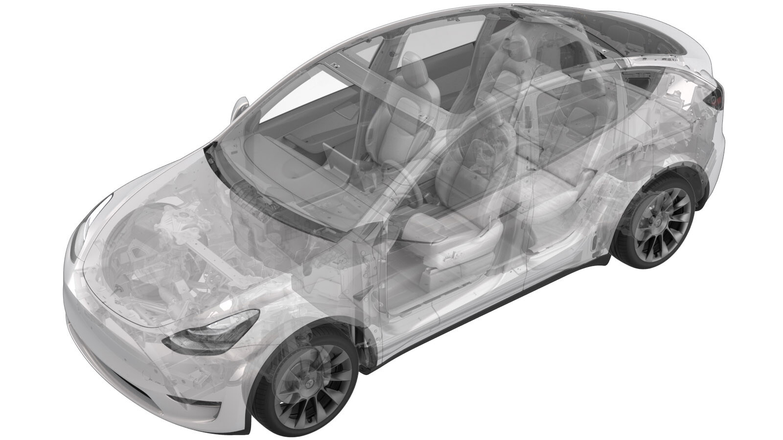
Barra colectora - Fusible auxiliar - Batería de alta tensión (Paquete estructural) (Desinstalación y sustitución)
 Código de corrección
16307302 2.40
NOTA: Salvo que se indique lo contrario explícitamente en el procedimiento, el código de corrección anterior y el FRT reflejan todo el trabajo necesario para realizar este procedimiento, incluidos los procedimientos vinculados. No acumule códigos de corrección a menos que se le indique explícitamente que lo haga.
NOTA: Consulte Tiempos de tarifa plana (FRT) para obtener más información sobre los FRT y cómo se crean. Para enviar sus comentarios sobre los valores de FRT, escriba a ServiceManualFeedback@tesla.com.
NOTA: Consulte Protección personal para asegurarse de llevar el EPI adecuado al realizar el siguiente procedimiento. Consulte Precauciones ergonómicas para ver prácticas de trabajo seguras.
- Open all the doors and lower all the windows.
-
Place vehicle in service mode with touchscreen
NotaHold Tesla T icon at top of center display for four seconds and then type "service" into dialog box
- Remove the ancillary bay cover. See Cubierta - Compartimento auxiliar (Paquete estructural) (Desinstalación y sustitución).
- Retire el dispositivo pirotécnico de desconexión de la batería. Consulte Dispositivo pirotécnico de desconexión de la batería (Paquete estructural) (desinstalación y sustitución).
-
Disconnect HV controller connectors
Nota7x connectors, Lift hinge upwards to release levered connection
-
Release harness clips from HVC hinge tray and route harness away
Nota3x clips
-
Remove bolts securing HV controller hinge tray to HV battery
Nota2x bolts, 8mm, 2 Nm
-
Remove HV controller and tray from ancillary bay
-
Remove 63A fuse cover
Nota2x securing tabs
-
Disconnect HVIL connector from HV heatpump harness
Nota1x connector
-
Remove 63A fuse from ancillary bay
Nota2x nuts, 8mm, 2.5 Nm, Discard after removal
-
Remove inner 63A fuse from ancillary bay
Nota2x nuts, 8mm, 2.5 Nm, Discard after removal
-
Remove ancillary bay harness from plastic bobbin stud
-
Remove bolts securing PCS to HV battery
Nota6x bolts, 8mm, 6 Nm, Ensure ONLY the 8mm fasteners are removed, Do not remove the T30 fasteners
-
Remove ancillary bay harness from negative DC link
Nota1x nut, 8mm, 1.5 Nm, Discard nut after removal
-
Release ancillary bay harness from tray between PCS and bobbin
Nota1x clip
-
Remove nut securing auxiliary fuse jumper busbar
Nota1x nut, 8mm, 2.5 Nm, Discard after removal, Slightly shift PCS to gain access to nut, Discard nut after removal
-
Remove auxiliary fuse jumper busbar
-
Install auxiliary fuse jumper busbar
-
Install nut securing auxiliary fuse jumper busbar
Nota1x nut, 8mm, 2.5 Nm, Install new nut, Shift PCS back into original position
-
Install bolts securing PCS to HV battery
Nota6x bolts, 8mm, 6 Nm
-
Secure ancillary bay harness onto tray between PCS and bobbin
Nota1x clip
-
Install ancillary bay harness to negative DC link
Nota1x nut, 8mm, 1.5 Nm, Install new nut
-
Install ancillary bay harness from plastic bobbin stud
-
Install inner 63A fuse into ancillary bay
Nota2x nuts, 8mm, 2.5 Nm, Install new nuts
-
Install 63A fuse into ancillary bay
Nota2x nuts, 8mm, 2.5 Nm, Install new nuts
-
Place holder- Perform Hioki measurement at the joint from 63A fuse to terminal
Nota1x HV joint, 105µΩ or less, Perform zero adjust to Hioki meter prior to testing
-
Place holder- Perform Hioki measurement at the joint of 63A fuse to auxiliary jumper busbar
Nota1x HV joint, 105µΩ or less, Perform zero adjust to Hioki meter prior to testing
-
Place holder- Perform Hioki measurement at the joint of inner 63A fuse to flag nut
Nota1x HV joint, 105µΩ or less, Perform zero adjust to Hioki meter prior to testing
-
Place holder- Perform Hioki measurement at the joint of inner 63A fuse to auxiliary jumper busbar
Nota1x HV joint, 105µΩ or less, Perform zero adjust to Hioki meter prior to testing
-
Connect HVIL connector onto tray
Nota1x connector
-
Install 63A fuse cover
Nota2x securing tabs
-
Position HV controller and tray into ancillary bay
-
Install bolts securing HV controller hinge tray to HV battery
Nota2x bolts, 8mm, 2 Nm
- Mida la tensión en los puntos de montaje del dispositivo pirotécnico de desconexión de la batería y, a continuación, instale el dispositivo pirotécnico de desconexión de la batería. Consulte Dispositivo pirotécnico de desconexión de la batería (Paquete estructural) (desinstalación y sustitución).
- Install the ancillary bay cover. See Cubierta - Compartimento auxiliar (Paquete estructural) (Desinstalación y sustitución).
-
Exit Service Mode through UI
NotaControls > Service Mode > Exit Service Mode
- Raise all the windows
-
Close all the doors
NotaIf 12V is powered up, Unlatch rear doors before closing