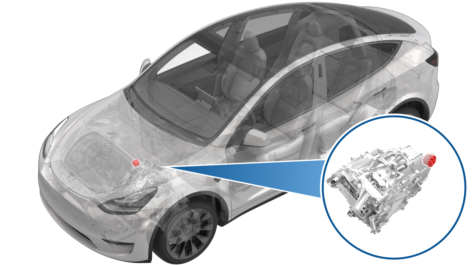
Casquillo - Unidad de tracción delantera - Lado derecho (desinstalación y sustitución)
 Código de corrección
39011102 2.70
NOTA: Salvo que se indique lo contrario explícitamente en el procedimiento, el código de corrección anterior y el FRT reflejan todo el trabajo necesario para realizar este procedimiento, incluidos los procedimientos vinculados. No acumule códigos de corrección a menos que se le indique explícitamente que lo haga.
NOTA: Consulte Tiempos de tarifa plana (FRT) para obtener más información sobre los FRT y cómo se crean. Para enviar sus comentarios sobre los valores de FRT, escriba a ServiceManualFeedback@tesla.com.
NOTA: Consulte Protección personal para asegurarse de llevar el EPI adecuado al realizar el siguiente procedimiento. Consulte Precauciones ergonómicas para ver prácticas de trabajo seguras.
- 2025-04-04: Added step to refer to the suspension alignment tables to define whether an alignment check is required and, if so, what type of alignment check is required.
Retirar
- Remove the front subframe assembly from the vehicle. See Conjunto del bastidor auxiliar - Parte delantera (motor dual) (Desinstalación e instalación).
-
Install the bushing tool on the RH
front drive unit bushing.
NotaUse cups "K", "B", and "I" when assembling the special tool, as shown.
Figura 1. Other assemblies hidden for clarity -
Turn the bearing-side bushing tool nut
with a wrench while holding the opposite nut in place.
PRECAUCIÓNApply torque only to the bearing-side bushing tool nut.
Figura 2. Apply torque only to the nut highlighted red -
When the bushing has been pushed out
of the front drive unit, separate the bushing tool, and then remove the bushing.
Instalar
-
Coloque la herramienta para casquillos para insertar el casquillo nuevo.
NotaUse cups "L", "J", and "C" when assembling the special tool, as shown.NotaMake sure the rubber tab is visible at the top of cup "J".
Figura 3. Cups "L", "J", and "C" used to install the bushing Figura 4. Rubber tab visible at the top of cup "J" -
Turn the bearing-side bushing tool nut
with a wrench until the bushing flange makes contact with the front drive unit.
PRECAUCIÓNApply torque only to the bearing-side bushing tool nut.NotaWhile installing the bushing, make sure the rubber tab remains visible at the top of cup "J".
Figura 5. Apply torque only to the nut highlighted red - Separe la herramienta para casquillos y, a continuación, retírela de la unidad de tracción.
-
Make sure the bushing alignment lug is
oriented to 12 o'clock.
Figura 6. Other assemblies hidden for clarity - Install the front subframe assembly on the vehicle. See Conjunto del bastidor auxiliar - Parte delantera (motor dual) (Desinstalación e instalación).
- Consulte las tablas de requisitos de alineación para determinar si es necesario realizar una comprobación de la alineación del EPAS (EC) o una comprobación de la alineación de las cuatro ruedas (AC). Si se realiza, añada el código de corrección de ajuste/comprobación de la alineación por separado. Consulte Requisito de alineación - Suspensión.