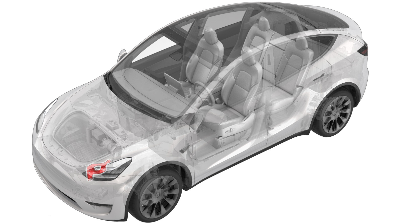
Soporte - Módulo del extremo delantero (FEM) - Lado izquierdo (Desinstalación y sustitución)
 Código de corrección
10101032 0.78
NOTA: Salvo que se indique lo contrario explícitamente en el procedimiento, el código de corrección anterior y el FRT reflejan todo el trabajo necesario para realizar este procedimiento, incluidos los procedimientos vinculados. No acumule códigos de corrección a menos que se le indique explícitamente que lo haga.
NOTA: Consulte Tiempos de tarifa plana (FRT) para obtener más información sobre los FRT y cómo se crean. Para enviar sus comentarios sobre los valores de FRT, escriba a ServiceManualFeedback@tesla.com.
NOTA: Consulte Protección personal para asegurarse de llevar el EPI adecuado al realizar el siguiente procedimiento. Consulte Precauciones ergonómicas para ver prácticas de trabajo seguras.
Especificaciones de apriete
| Descripción | Valor de apriete | Herramientas recomendadas | Reutilizar/Sustituir | Notas |
|---|---|---|---|---|
| Pernos que sujetan el soporte del módulo delantero del lado izquierdo al vehículo |
 35 Nm (25.8 lbs-ft) |
|
Reutilizar | |
| Perno que sujeta el soporte de la aleta guardabarros delantera izquierda al conjunto de la aleta guardabarros delantera |
 9.8 Nm (7.2 lbs-ft) |
|
Reutilizar | |
| Perno que sujeta el soporte del módulo delantero del lado izquierdo al soporte delantero |
 16 Nm (11.8 lbs-ft) |
|
Reutilizar |
Retirar
- Disconnect 12V power. See Alimentación de 12 V/baja tensión (Desconexión y conexión).
- Remove the front fascia. See Defensa - Delantera (Desinstalación e instalación).
-
Remove the LH front ride height sensor harness from the FEM bracket assembly.
Nota2x clips
-
Disconnect the LH front ride height sensor connector.
Nota1x connector
-
Disconnect the LH front wheel speed sensor connector.
Nota1x clip, 1x connector, Release locking tab
-
Disconnect the LH FEM harness connector.
Nota1x connector, Disengage locking tab
-
Disconnect the cooling fan module connector.
Nota1x connector, Disconnect this after coolant hose is capped to avoid coolant damaging connector
-
Release the cooling fan module harness from the FEM bracket assembly.
Nota1x clip
-
Disconnect the connectors from horn assembly.
Nota2x connectors
-
Disconnect the LH headlamp connector.
Nota1x connector, Pull tab to disengage lock mechanism, Pull again to release connector, Do not press down on tab
- Remove the LH impact accelerometer. See Sensor - Impacto/acelerómetro - Parachoques delantero - Lado izquierdo (Desinstalación y sustitución)
-
Release the clips that attach the FEM electrical harness to the front end carrier, and then remove the harness from the front end carrier.
Nota1x clip
-
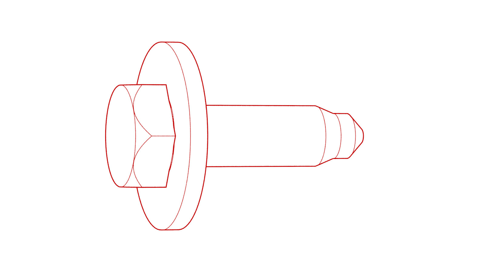
Remove the bolts (x3) that attach the front end module bracket assembly to the vehicle.
 35 Nm (25.8 lbs-ft)TIpSe recomienda utilizar las siguientes herramientas:
- Vaso de 13 mm
- Llave de carraca/dinamométrica
-
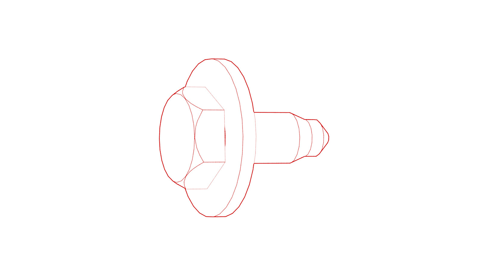
Remove the bolt that attach the front end module bracket to the front fender assembly.
 9.8 Nm (7.2 lbs-ft)TIpSe recomienda utilizar las siguientes herramientas:
- Vaso de 10 mm de cuello largo
- Extensión de 4 pulg.
- Llave de carraca/dinamométrica
-
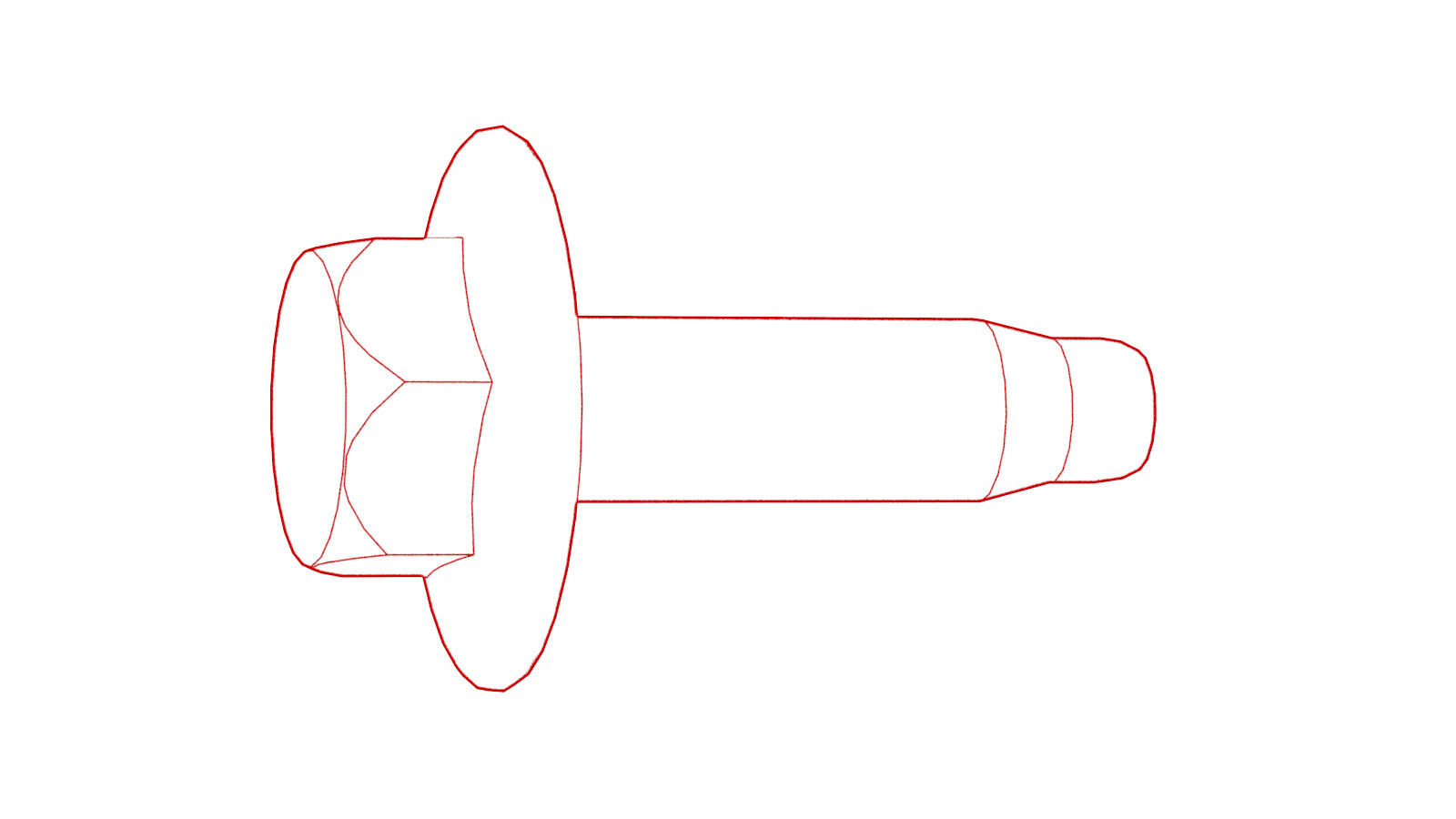
Remove the bolt that attach the front end module bracket to the front end carrier.
 16 Nm (11.8 lbs-ft)TIpSe recomienda utilizar las siguientes herramientas:
- Vaso de 13 mm
- Extensión de 6 pulg.
- Llave dinamométrica de carraca de cabezal flexible/cabezal flexible
Instalar
-
Install the bolt that attach the front end module bracket to the front end carrier.
 16 Nm (11.8 lbs-ft)TIpSe recomienda utilizar las siguientes herramientas:
- Vaso de 13 mm
- Extensión de 6 pulg.
- Llave dinamométrica de carraca de cabezal flexible/cabezal flexible
-
Install the bolt that attach the front end module bracket to the front fender assembly.
 9.8 Nm (7.2 lbs-ft)TIpSe recomienda utilizar las siguientes herramientas:
- Vaso de 10 mm de cuello largo
- Extensión de 4 pulg.
- Llave de carraca/dinamométrica
-
Remove the bolts (x3) that attach the front end module bracket assembly to the vehicle.
 35 Nm (25.8 lbs-ft)TIpSe recomienda utilizar las siguientes herramientas:
- Vaso de 13 mm
- Llave de carraca/dinamométrica
-
Route the front harness through the LH FEM bracket assembly, and secure the front harness to the bracket.
Nota1x clip
- Install the LH impact accelerometer. See Sensor - Impacto/acelerómetro - Parachoques delantero - Lado izquierdo (Desinstalación y sustitución)
-
Connect the LH headlamp connector.
Nota1x connector, 1x locking tab
-
Connect the horn assembly connectors.
Nota2x connectors
-
Connect the cooling fan module connectors and then install the clip.
Nota1x clipNota1x connector
-
Connect the LH FEM harness connector.
Nota1x connector, Engage locking tab
-
Connect the LH front ride height sensor connector and then install the clips.
Nota2x clips, 1x connector
-
Connect the LF wheel speed sensor connector.
Nota1x clip, 1x connector, Engage locking tab
- Install the front fascia. See Defensa - Delantera (Desinstalación e instalación).
- Connect 12V power. See Alimentación de 12 V/baja tensión (Desconexión y conexión).