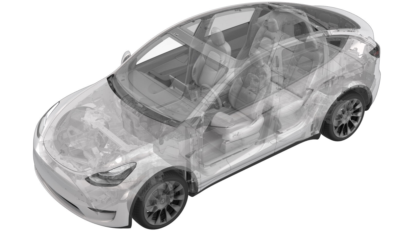
Contactor - Negativo - Batería de alta tensión (Paquete estructural) (Desinstalación y sustitución)
 Código de corrección
16302012 1.98
NOTA: Salvo que se indique lo contrario explícitamente en el procedimiento, el código de corrección anterior y el FRT reflejan todo el trabajo necesario para realizar este procedimiento, incluidos los procedimientos vinculados. No acumule códigos de corrección a menos que se le indique explícitamente que lo haga.
NOTA: Consulte Tiempos de tarifa plana (FRT) para obtener más información sobre los FRT y cómo se crean. Para enviar sus comentarios sobre los valores de FRT, escriba a ServiceManualFeedback@tesla.com.
NOTA: Consulte Protección personal para asegurarse de llevar el EPI adecuado al realizar el siguiente procedimiento. Consulte Precauciones ergonómicas para ver prácticas de trabajo seguras.
Retirar
- Open all the doors and lower all the windows.
- Place the vehicle into Service Mode. See Modo de servicio.
- Remove the ancillary bay cover. See Cubierta - Compartimento auxiliar (Paquete estructural) (Desinstalación y sustitución).
- Retire el dispositivo pirotécnico de desconexión de la batería. Consulte Dispositivo pirotécnico de desconexión de la batería (Paquete estructural) (desinstalación y sustitución).
-
Disconnect the HV battery negative
contactor connectors (x2).
-
Release the clip that attaches the
ancillary bay harness to the vehicle.
-
Remove and discard the bolts (x2) that
attach the negative contactor to the busbars.
 5 Nm (3.7 lbs-ft) + 60 degreesTIpSe recomienda utilizar las siguientes herramientas:
- Vaso de 13 mm
-
Remove the bolts (x3) that attach the
negative contactor to the assembly tray.
 6 Nm (4.4 lbs-ft)TIpSe recomienda utilizar las siguientes herramientas:
- Vaso de 8 mm
-
Remove the HV battery negative pack
contactor from the ancillary bay.
Instalar
-
Position the HV battery negative
contactor into the ancillary bay.
-
Install the bolts (x3) that attach the
negative contactor to the assembly tray.
 6 Nm (4.4 lbs-ft)NotaHand start bolts to verify the contactor is centered.TIpSe recomienda utilizar las siguientes herramientas:
- Vaso de 8 mm
-
Install new bolts (x2) that attach the
negative contactor to the busbars.
 5 Nm (3.7 lbs-ft) + 60 degreesTIpSe recomienda utilizar las siguientes herramientas:
- Vaso de 13 mm
-
Use a Hioki resistance meter to
measure the resistance at the HV joint between the newly-installed negative contactor
and the negative DC link busbar.
NotaThe acceptable resistance is between 0.004 mΩ (4 μΩ) and 0.050 mΩ (50 μΩ). If the resistance is greater than 0.050 mΩ (50 μΩ), there is too much resistance in the High Voltage joint. Remove the fastener, clean areas with isopropyl alcohol, install fastener back and test again. If the resistance is less than 0.004 mΩ (4 μΩ), reposition the probes and measure again.
-
Use a Hioki resistance meter to
measure the resistance at the HV joint between the newly-installed negative contactor
and the negative terminal flex assembly.
NotaThe acceptable resistance is between 0.004 mΩ (4 μΩ) and 0.050 mΩ (50 μΩ). If the resistance is greater than 0.050 mΩ (50 μΩ), there is too much resistance in the High Voltage joint. Remove the fastener, clean areas with isopropyl alcohol, install fastener back and test again. If the resistance is less than 0.004 mΩ (4 μΩ), reposition the probes and measure again.
-
Install the clip that attaches the
ancillary bay harness to the vehicle.
-
Connect the negative contactor
connectors (x2).
- Mida la tensión en los puntos de montaje del dispositivo pirotécnico de desconexión de la batería y, a continuación, instale el dispositivo pirotécnico de desconexión de la batería. Consulte Dispositivo pirotécnico de desconexión de la batería (Paquete estructural) (desinstalación y sustitución).
- Install the ancillary bay cover. See Cubierta - Compartimento auxiliar (Paquete estructural) (Desinstalación y sustitución).
- Exit Service Mode. See Modo de servicio.
- Remove the vehicle from the lift. See Elevación del vehículo - Elevador de 2 columnas.
- Raise all the windows and close all the doors.