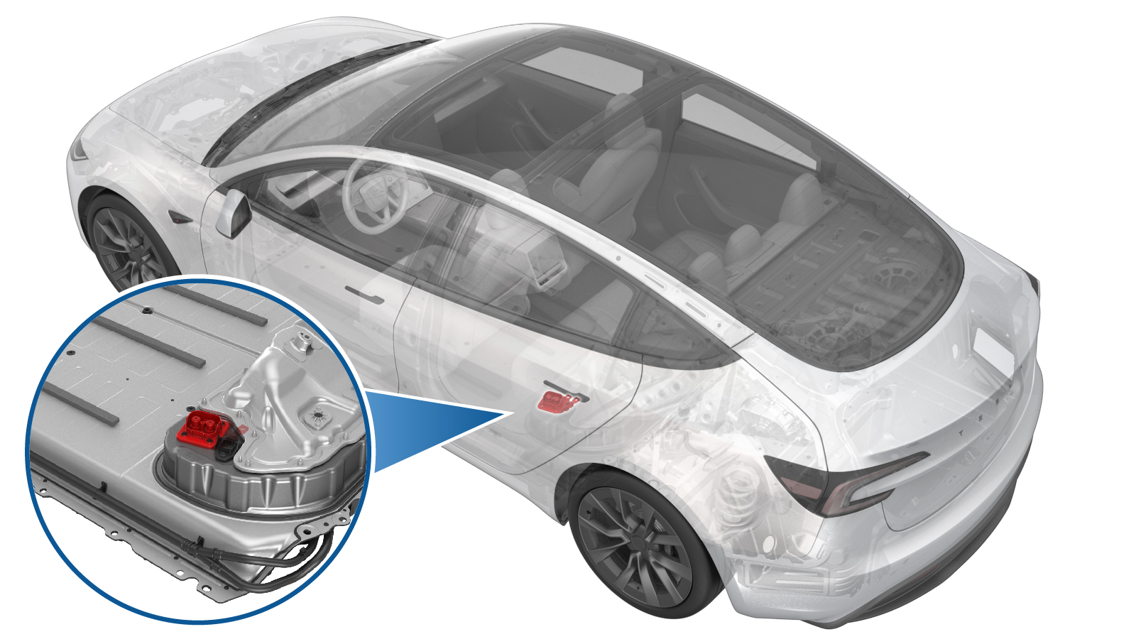
Header - Busbar DC Input (Remove and Replace)
 Código de corrección
1630010292
FRT
1.26
NOTA: Salvo que se indique lo contrario explícitamente en el procedimiento, el código de corrección anterior y el FRT reflejan todo el trabajo necesario para realizar este procedimiento, incluidos los procedimientos vinculados. No acumule códigos de corrección a menos que se le indique explícitamente que lo haga.
NOTA: Consulte Tiempos de tarifa plana (FRT) para obtener más información sobre los FRT y cómo se crean. Para enviar sus comentarios sobre los valores de FRT, escriba a ServiceManualFeedback@tesla.com.
NOTA: Consulte Protección personal para asegurarse de llevar el EPI adecuado al realizar el siguiente procedimiento.
NOTA: Consulte Precauciones ergonómicas para ver información sobre prácticas de trabajo seguras.
- 2025-06-04: Added instruction to zero adjust the Hioki resistance meter prior to measurement, added max. resistance value and updated torque values.
Retirar
- Remove the ancillary bay cover. See Ancillary Bay Cover (Remove and Replace).
- Inspect ancillary bay for any missing insulators and install the new insulators if necessary.
-
Remove bolt (X1) securing pyro disconnect to ancillary bay, and the remove the pyro from ancillary bay.
TIpSe recomienda utilizar las siguientes herramientas:
- Extensión de 4 pulg.
- Vaso de 13 mm
-
Install pyro disconnect dummy.
-
Disconnect megaharness connector from DC input assembly
-
Remove insulator for DC input assembly to both fastcharge busbar inlet side
-
Remove bolt (X1) securing negative fastcharge busbar inlet side and negative DC input assembly busbar.
TIpSe recomienda utilizar las siguientes herramientas:
- Extensión de 4 pulg.
- Vaso de 13 mm
-
Remove bolt securing positive fastcharge busbar inlet side and positive DC input assembly busbar.
TIpSe recomienda utilizar las siguientes herramientas:
- Extensión de 4 pulg.
- Vaso de 13 mm
-
Remove bolts securing busbar DC input assembly to ancillary bay.
TIpSe recomienda utilizar las siguientes herramientas:
- Extensión de 4 pulg.
- Vaso de 13 mm
-
Remove Busbar DC input assembly from ancillary bay.
Instalar
-
Install Busbar DC input assembly to ancillary bay.
AvisoLos vídeos incluidos en este procedimiento se ofrecen únicamente a modo de descripción general complementaria. Siga todos los pasos indicados en el procedimiento para evitar daños en los componentes y/o lesiones personales.
-
Install the bolts (x4) securing busbar DC input assembly to ancillary bay.
 10 Nm (7.4 lbs-ft)TIpSe recomienda utilizar las siguientes herramientas:
- Extensión de 4 pulg.
-
Install and torque bolt securing negative fastcharge busbar inlet and negative DC input link to 15 Nm, loosen 180 degrees, and then torque to 5 Nm + 60 degrees.
TIpSe recomienda utilizar las siguientes herramientas:
- Extensión de 4 pulg.
- Vaso de 13 mm
-
Install and torque bolt securing positive fastcharge busbar inlet and positive DC input link to 15 Nm, loosen 180 degrees, and then torque to 5 Nm + 60 degrees.
TIpSe recomienda utilizar las siguientes herramientas:
- Extensión de 4 pulg.
- Vaso de 13 mm
- Perform zero adjust to Hioki meter. See Medidor de resistencia (Ajuste a cero).
-
Perform Hioki resistance test at both HV joints of DC input assembly busbar.
NotaResistance must be 60 𝜇Ω or less. Test from negative fastcharge busbar to negative DC input busbar and positive fastcharge busbar to positive DC input busbar.
-
Install insulator for DC input assembly to both fast charge busbars inlet side.
-
Connect megaharness connector to DC input assembly.
-
Remove pyro disconnect dummy.
- Install the ancillary bay cover. See Ancillary Bay Cover (Remove and Replace).