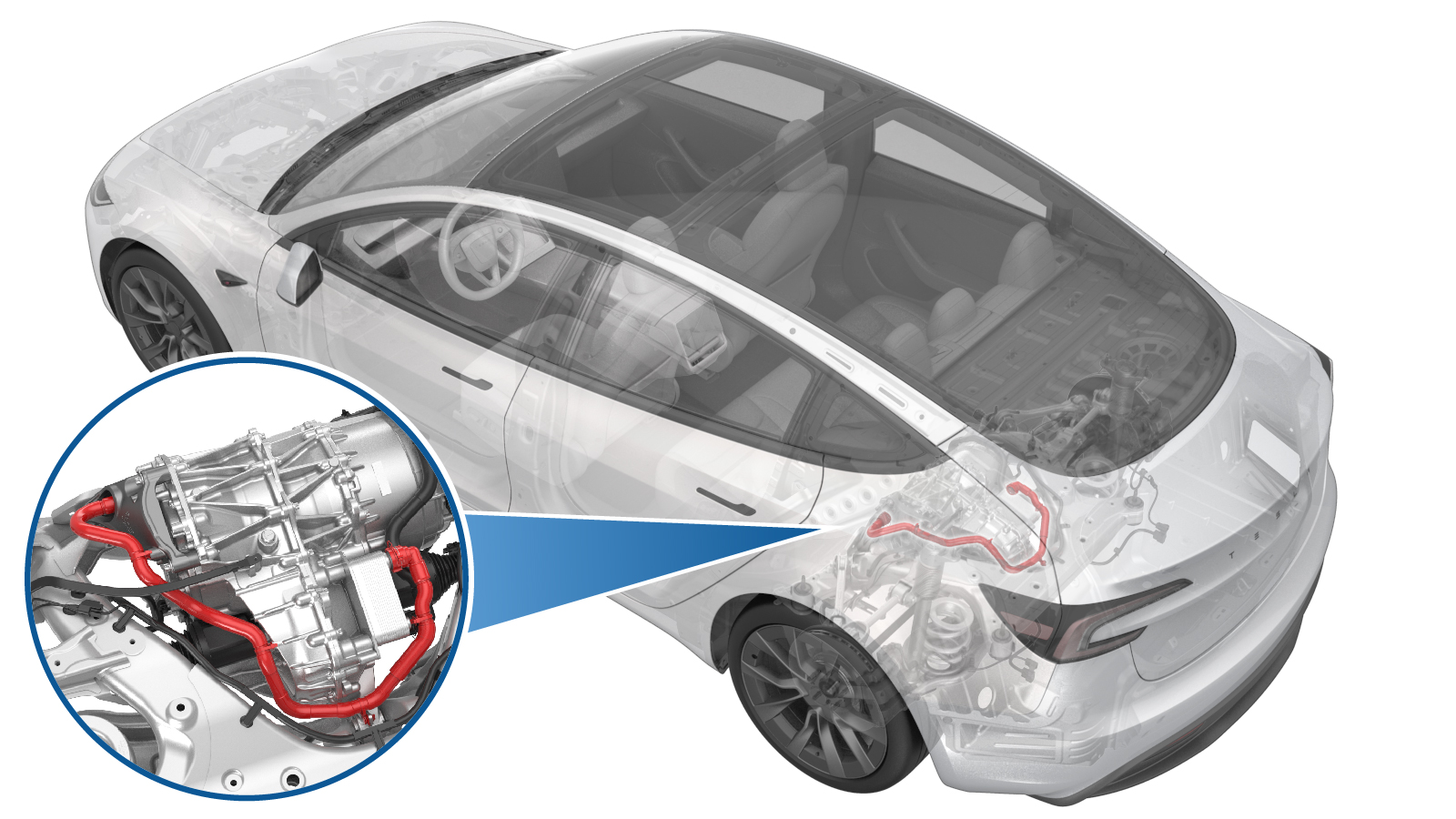
Hose - Rear Drive Unit to Oil Coller (Remove and Replace)
 Código de corrección
1830020022
FRT
1.98
NOTA: Salvo que se indique lo contrario explícitamente en el procedimiento, el código de corrección anterior y el FRT reflejan todo el trabajo necesario para realizar este procedimiento, incluidos los procedimientos vinculados. No acumule códigos de corrección a menos que se le indique explícitamente que lo haga.
NOTA: Consulte Tiempos de tarifa plana (FRT) para obtener más información sobre los FRT y cómo se crean. Para enviar sus comentarios sobre los valores de FRT, escriba a ServiceManualFeedback@tesla.com.
NOTA: Consulte Protección personal para asegurarse de llevar el EPI adecuado al realizar el siguiente procedimiento.
NOTA: Consulte Precauciones ergonómicas para ver información sobre prácticas de trabajo seguras.
Retirar
- Remove the rear subframe assembly. See Subframe Assembly - Rear (Remove and Replace).
-
Partially lower the rear subframe and drive unit assembly.
-
Tilt the subframe fixture
forward.
NotaAdjust the powertrain lift and tilt it forward in order to access motor mount fasteners.
-
Release the rear drive unit inverter
to oil cooler hose.
Nota1x hose clip, Image zoomed in for clarity.
-
Release the rear drive unit inverter
coolant hose from heat exchanger.
NotaUse a foldable funnel as required.
-
Release clips (x4) that attach the
rear drive unit inverter to oil cooler hose and remove the hose.
Instalar
-
Position and secure the clips (x4)
that secure the rear drive unit inverter to coolant hose.
-
Secure the rear drive unit inverter to
oil cooler hose onto the heat exchanger.
NotaClean excess coolant from the area. Perform a push-pull-push test to make sure the hose is fully engaged.
-
Secure the inverter to cooler hose to
inverter.
NotaPerform a push-pull-push test to make sure the hose is fully engaged.
-
Tilt the subframe fixture backwards to
original position.
-
Raise the partially lowered
subframe.
PRECAUCIÓNUse caution to not damage components while raising the subframe.
- Install the rear subframe assembly. See Subframe Assembly - Rear (Remove and Replace).