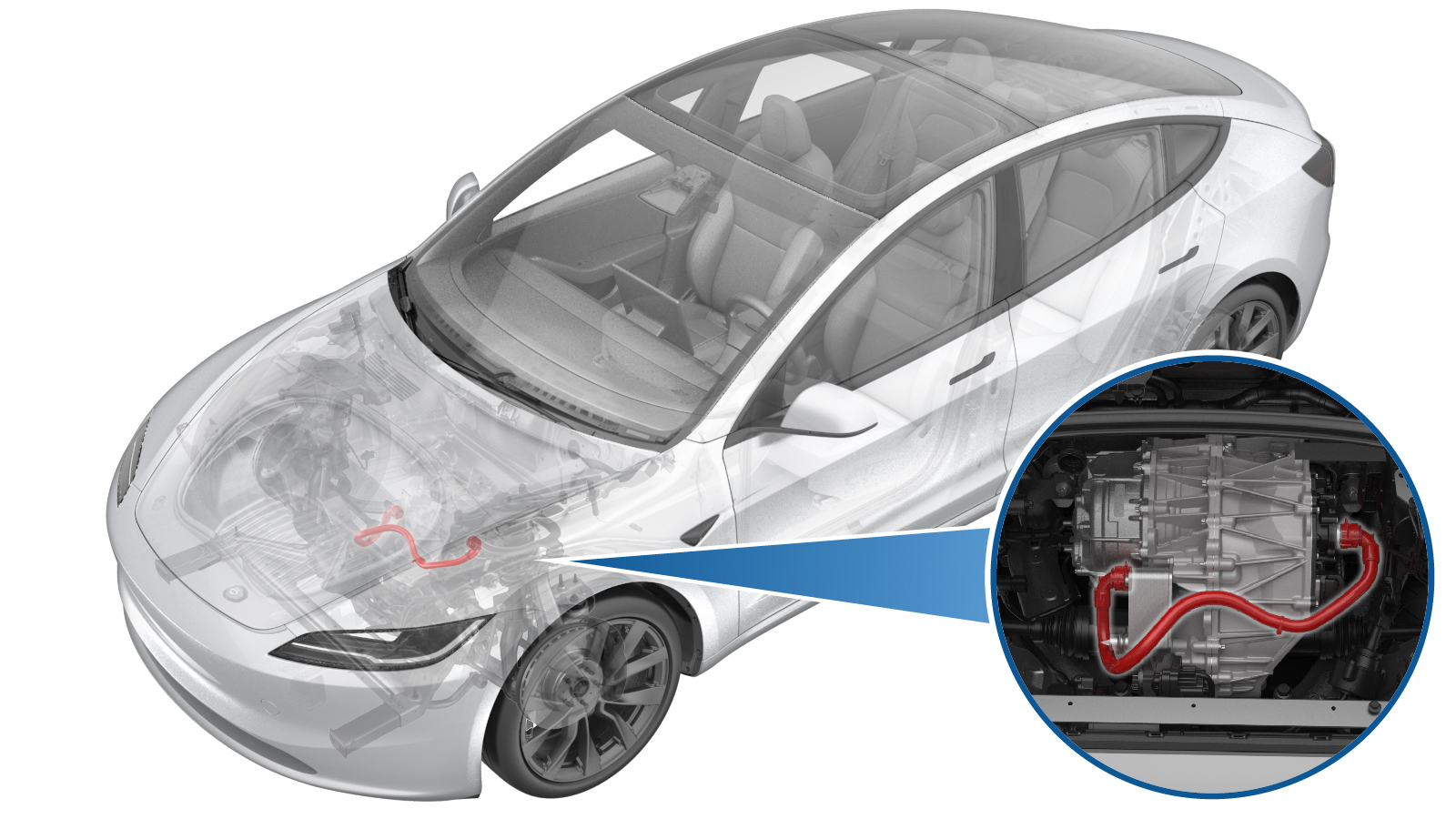
Hose - Front Drive Unit to Oil Cooler (Remove and Replace)
 Código de corrección
1830020122
FRT
0.42
NOTA: Salvo que se indique lo contrario explícitamente en el procedimiento, el código de corrección anterior y el FRT reflejan todo el trabajo necesario para realizar este procedimiento, incluidos los procedimientos vinculados. No acumule códigos de corrección a menos que se le indique explícitamente que lo haga.
NOTA: Consulte Tiempos de tarifa plana (FRT) para obtener más información sobre los FRT y cómo se crean. Para enviar sus comentarios sobre los valores de FRT, escriba a ServiceManualFeedback@tesla.com.
NOTA: Consulte Protección personal para asegurarse de llevar el EPI adecuado al realizar el siguiente procedimiento.
NOTA: Consulte Precauciones ergonómicas para ver información sobre prácticas de trabajo seguras.
Código de corrección
1830020122
FRT
0.42
NOTA: Salvo que se indique lo contrario explícitamente en el procedimiento, el código de corrección anterior y el FRT reflejan todo el trabajo necesario para realizar este procedimiento, incluidos los procedimientos vinculados. No acumule códigos de corrección a menos que se le indique explícitamente que lo haga.
NOTA: Consulte Tiempos de tarifa plana (FRT) para obtener más información sobre los FRT y cómo se crean. Para enviar sus comentarios sobre los valores de FRT, escriba a ServiceManualFeedback@tesla.com.
NOTA: Consulte Protección personal para asegurarse de llevar el EPI adecuado al realizar el siguiente procedimiento.
NOTA: Consulte Precauciones ergonómicas para ver información sobre prácticas de trabajo seguras.
- 1135762-00-A Kit, tapón de mantenimiento, manguera de refrigeración, Model 3
- 1080568-00-A Fluid Catcher
- 1065131-00-A Battery Coolant Drain Kit
Retirar
- Raise and support the vehicle. See Elevación del vehículo - Elevador de 2 columnas.
- Disconnect the LV power. See LV Power (Disconnect and Connect).
- Remove the underhood storage unit. See Underhood Storage Unit (Remove and Replace).
-
Raise the vehicle fully and lower the lift onto locks.
PRECAUCIÓN
Make sure there is an audible click of the locks on both sides before lowering, otherwise the vehicle may tilt to one side.
Make sure that the doors are clear of surrounding objects.
- Remove the front aero shield panel. See Panel - Aero Shield - Front (Remove and Replace).
-
Position a coolant drain container underneath LH front of the HV battery.
-
Disconnect the front drive unit inverter inlet hose from the fluid coupling, and plug the ends of both fittings as soon as possible to avoid coolant loss.
NotaCoolant loss greater than 1L requires vacuum fill.
-
Position the coolant drain underneath RH front of the front drive unit.
-
Disconnect the front drive unit inverter inlet hose from the heat exchanger, and plug the ends of both fittings as soon as possible to avoid coolant loss.
NotaCoolant loss greater than 1L requires vacuum fill.
- Remove the coolant drain container from underneath the vehicle.
- Raise the lift off locks, hold the lock release lever to keep locks free while the vehicle is lowered, and then set the vehicle to a comfortable working height, then set the lift onto locks.
-
Release the inverter to oil cooler hose clip, and then remove the inverter to oil cooler hose from the front drive unit.
Instalar
-
Install the inverter to oil cooler hose to the front drive unit by securing the inverter to oil cooler hose clip.
-
Raise the vehicle fully and lower the lift onto locks.
PRECAUCIÓN
Make sure there is an audible click of the locks on both sides before lowering, otherwise the vehicle may tilt to one side.
Make sure that the doors are clear of surrounding objects.
-
Position a coolant drain container underneath the LH front of the HV battery.
-
Remove the plugs from the ends of both fittings, and then connect the front drive unit inverter inlet hose to the fluid coupling.
Nota
Perform a push-pull-push test to make sure the hose is fully engaged. Coolant loss greater than 1L requires vacuum fill.
-
Position the coolant drain underneath the RH front of the front drive unit.
-
Remove the plugs from the ends of both fittings, and then connect the front drive unit inverter inlet hose to the heat exchanger.
Nota
Perform a push-pull-push test to make sure the hose is fully engaged. Coolant loss greater than 1L requires vacuum fill.
- Remove the coolant drain container from underneath the vehicle.
- Install the front aero shield panel. See Panel - Aero Shield - Front (Remove and Replace).
- Raise the lift off locks, hold the lock release lever to keep locks free while the vehicle is lowered, and then fully lower the vehicle.
- Connect the LV power. See LV Power (Disconnect and Connect).
-
Remove the coolant cap and fill the coolant to MAX line.
- Unlock the gateway. See Desbloqueo de la puerta de enlace.
-
Tap the Service Mode "wrench" (at the bottom of the touchscreen UI), and then tap to perform the Coolant Air Purge.
Nota
- Make sure that the vehicle is not in Drive. Putting the vehicle into Drive will stop this routine.
- The pumps will still run for some time after the Routine Passed message displays. Do not start another routine before the coolant pumps stop running.
- The speed in the test varies from 3500-6500 RPM (idle speed = ~1500 RPM) and the actuated valve varies between SERIES and PARALLEL.
- Si el régimen ronda las 7000 rpm, significa que las bombas están bloqueadas por el aire. Vuelva a realizar el llenado de vacío. Continúe añadiendo refrigerante y purgue hasta que el nivel de refrigerante esté entre las líneas NOM y MAX de la botella.
- Inspect the coolant level and top off as necessary, make sure that the fluid level is at the MAX line, and then install the coolant bottle cap.
- Install the underhood storage unit. See Underhood Storage Unit (Remove and Replace).
- Install the rear underhood apron. See Underhood Apron - Rear (Remove and Replace).
- Raise the LH front window and close the LH front door.
- Remove the lift arms from below the vehicle.