2022-01-11
Battery Assembly
Correction code 16010102
Remove
- Remove rear diffuser tray panel (refer to procedure).
- Raise vehicle on 2 post ramp (refer to procedure).
- Remove both rear wheels (torque 105 Nm).
- Inhibit the APS via the touchscreen.
- Disengage park brake.
-
Remove the Power Electronics Module (PEM).
- Roadster 1.5: (refer to procedure)
- Roadster 2.X: (refer to procedure)
- Position container to collect coolant.
- Release clamps securing feed and return hoses to coolant manifold.
- Remove bolts (x2) securing motor cable to transmission (torque 35 Nm). Release cable and allow to hang.
-
Disconnect hoses from coolant manifold and allow coolant to drain.
CAUTIONCover the motor cable connector using tool 1001017 to prevent damage/contamination.
- Remove clip and clevis pin securing park brake primary cable to the park brake equalizer bracket.
- Disengage park brake.primary cable and remove LH and RH equalizer brackets.
- Remove Patchbolts (x6) securing park brake cable brackets to crossmember (torque 15 Nm).
-
Remove bolts (x3) securing mounting to transmission (torque 35 Nm).
NoteWhen installing, apply Loctite®242™ thread locking compound to bolt/screw threads.
- Remove bolt securing mounting to subframe and remove mounting (torque 80 Nm).
- Remove nuts (x2) securing brake hose P-clips to lower wishbones and release hoses (torque 9 Nm).
-
Remove bolts (x2) securing lower wishbones to crossmember (torque 45 Nm).
CAUTIONOnly tighten wishbone pivot bolts when the suspension is in ride height position. This can be achieved by either using the ride height tools or when the vehicle is on its wheels.
- Remove Nyloc nuts and bolts (x2) securing lower wishbones/track control arms to subframe (torque 60 Nm).
- Remove LH rear wheel arch liner (refer to procedure).
- Remove RH rear wheel arch liner (refer to procedure).
- Remove Nyloc nuts (x2) securing sway bar drop links to wishbones and release links (torque 45 Nm).
- Remove Nyloc nuts and bolts (x2) securing spring/damper assemblies to lower wishbones (torque 45 Nm).
- Remove Nyloc nuts and bolts (x2) securing spring/damper assemblies to subframe (torque 45 Nm).
- Disconnect the spring/damper assemblies.
- Position both lower wishbone assemblies aside, clear of the battery assembly.
-
Use side cutters or a rotary tool, such as a Dremel, to remove and discard clamps (x2) securing APS hoses to coolant hoses.
CAUTIONTake care not damage hoses when removing clamps.
- Disconnect APS hoses from coolant hoses.
- Disconnect the J4 ESS logic connector.
- Disconnect HVAC cable from battery.
- Disconnect 2-pin harness connector, battery to PEM.
- Remove nut and disconnect APS ground cable from post on chassis.
- Release cover on junction box.
- Remove nut and disconnect APS power cable from stud (torque 8 Nm). Wrap the APS power cable with electrical tape.
- Disconnect inertia switch and battery logic connectors in LH wheel arch.
- Remove bolt securing expansion tank to battery assembly.
- Remove bolts RH (x4) and LH (x4) bolts that secure the upper brackets on the PEM.
-
Remove bolts (x2) securing battery assembly to chassis (torque 18 Nm).
NoteWhen installing, apply Loctite®242™ thread locking compound to bolt/screw threads.
- Assemble components of battery lifting table (alignment pins, bearing table top and electric table lift).
- Position lift table and fixture below battery assembly to support its weight, level feet on fixture as required to support battery assembly evenly.
- Remove Patchbolts (x12) securing LH and RH support brackets to battery and subframe (torque 35 Nm).
- Remove support brackets.
- Remove bolts (x6) securing cross member to chassis (torque 35 Nm).
-
Remove bolts (x3) securing battery assembly to chassis (torque 18 Nm).
NoteWhen installing, apply Loctite®242™ thread locking compound to bolt/screw threads.
- With assistance, carefully lower battery assembly. Once the front of the battery assembly is clear of the chassis, push forward 30mm to gain access for the rear of the battery assembly.
- Remove nuts (x6) securing cross member to battery assembly and remove cross member (torque 35 Nm).
-
Disconnect the Battery Monitoring Board (BMB):
-
Remove the screws (x7) that attach the BMB cover to the battery assembly.

-
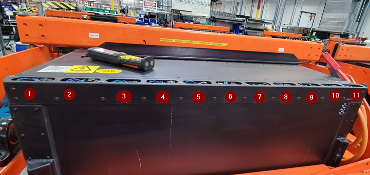
Locate the 11 cavities that need to have the BMB connector disconnected. The BMB connector must be disconnected in every cavity.
-
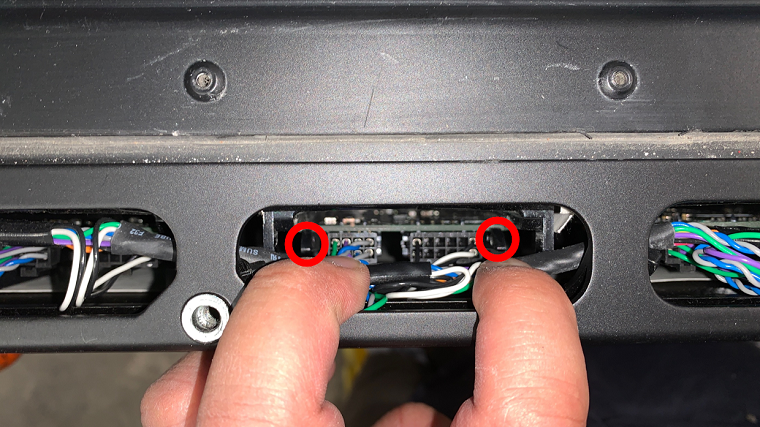
In Cavity 1, disconnect the electrical connector from the BMB by pressing the locking tab on each side of the electrical connector and pulling straight up.
TIpPlace a plastic trim tool between the locking tab and BMB on each side, and then use a pick to pull up the BMB between connectors.CAUTIONTake care not to damage components.CAUTIONMake sure the wires are out of the way so that they do not get pinched when the BMB cover is reinstalled.

-
Inspect the BMB cover gasket to confirm there is no damage. Replace if damaged.

-
Install the screws (x7) that attach the BMB cover to the battery assembly. Torque 1.7 Nm.
NoteReplace the screws before installing the battery assembly into the vehicle. If returning the battery assembly to remanufacturing the old screws can be used temporarily.
-
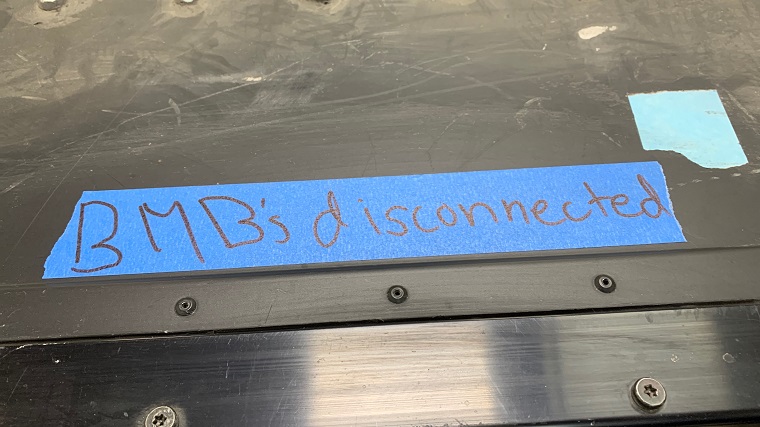
Place a strip of masking tape on the BMB cover and write "BMBs disconnected".
-
Remove the screws (x7) that attach the BMB cover to the battery assembly.


Install
-
Connect the Battery Monitoring Board (BMB):
-
Remove and discard the screws (x7) that attach the BMB cover to the battery assembly.
-
Locate the 11 cavities that need to have the BMB connector connected. The BMB connector must be connected in every cavity.
-
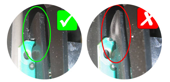
In Cavity 1, connect the electrical connector to the BMB by pressing the connector straight down and making sure the locking tabs are secure.
TIpInsert a pick into BMB between the connectors and push down for leverage.CAUTIONTake care not to damage components.CAUTIONMake sure the wires are out of the way so that they do not get pinched when the BMB cover is reinstalled.
-
Install new screws (x7) that attach the BMB cover to the battery assembly. Torque 1.7 Nm.
-
Remove and discard the screws (x7) that attach the BMB cover to the battery assembly.
- If a new battery is to be fitted, clean top of battery assembly and fit decking panel drain channels (x2).
- Position battery guide plates 1001018 (Battery Guide Plate) to subframe and secure with bolts (x6).
- If not already installed, position enclosure bumpers 1001021 (Battery Enclosure Bumpers) on battery.
- Install cross member to battery assembly and lightly tighten nuts prior to installing battery assembly.
- Make sure that motor cable, park brake cable, coolant hoses and electrical harnesses are positioned aside so as not to become trapped when raising the battery into position.
-
Slowly raise battery into position in vehicle until the front lip of the battery assembly is 50 mm from the chassis. Use the battery guide plates to direct the rear of the battery into the aperture.
NoteObserve all clearances between the battery, transmission and chassis.
- Release bearing table lock pins and adjust position of battery assembly to allow guide pins 1001009 (Battery Guide Pins) to be installed through the outermost holes on the lip of the battery assembly into the chassis.
- Raise battery fully into position ensuring that cross member is fully seated on chassis.
-
Install bolts (x3) securing battery assembly to chassis. Do not torque bolts at this time.
NoteWhen installing, apply Loctite®242™ thread locking compound to bolt/screw threads.
- Remove battery guide pins 1001009 (Battery Guide Pins) and battery guide plates 1001018 (Battery Guide Plate).
- Using alignment dowels 1001008 (Cross Member Alignment Dowels) to locate cross member on chassis. Fit and tighten bolts securing cross member to chassis (torque 35 Nm).
-
Using new Patchbolts, install LH and RH battery support brackets (torque 35 Nm).
CAUTIONAlways tighten the bolts to the battery assembly before tightening the bolts to the subframe otherwise structural damage to the battery assembly may occur.
- Lower lift table and position away from work area.
-
Install bolts (x2) securing battery assembly to chassis (torque 18 Nm).
NoteWhen installing, apply Loctite®242™ thread locking compound to bolt/screw threads.
- Tighten bolts (x3) securing battery assembly to chassis (torque 18 Nm).
- Tighten nuts (x6) securing cross member to battery assembly (torque 35 Nm).
- Working from right to left, check, and tighten bolts (x22) securing toe mount to battery assembly (torque 8 Nm).
- Working in the sequence shown, check and tighten bolts (x10) securing front lip to battery assembly (torque 6 Nm).


Installation procedure for remaining components is the reverse of removal, except for the following:
CAUTION
Replace all patchbolts.
CAUTION
Relace all nyloc nuts.
Refill and bleed the cooling system (refer to procedure).