2025-05-01
Power Electronics Module (PEM) - Roadster 2.x - Service Assessment
Correction code 39010800
- 2025-05-01: Released new procedure.
Inspection
- Remove the Power Electronics Module (PEM). See Power Electronics Module (PEM) - Roadster 2.x.
- Remove the VOID warranty labels (x2) and patch.
-
Remove the screws (x14) securing the PEM cover.
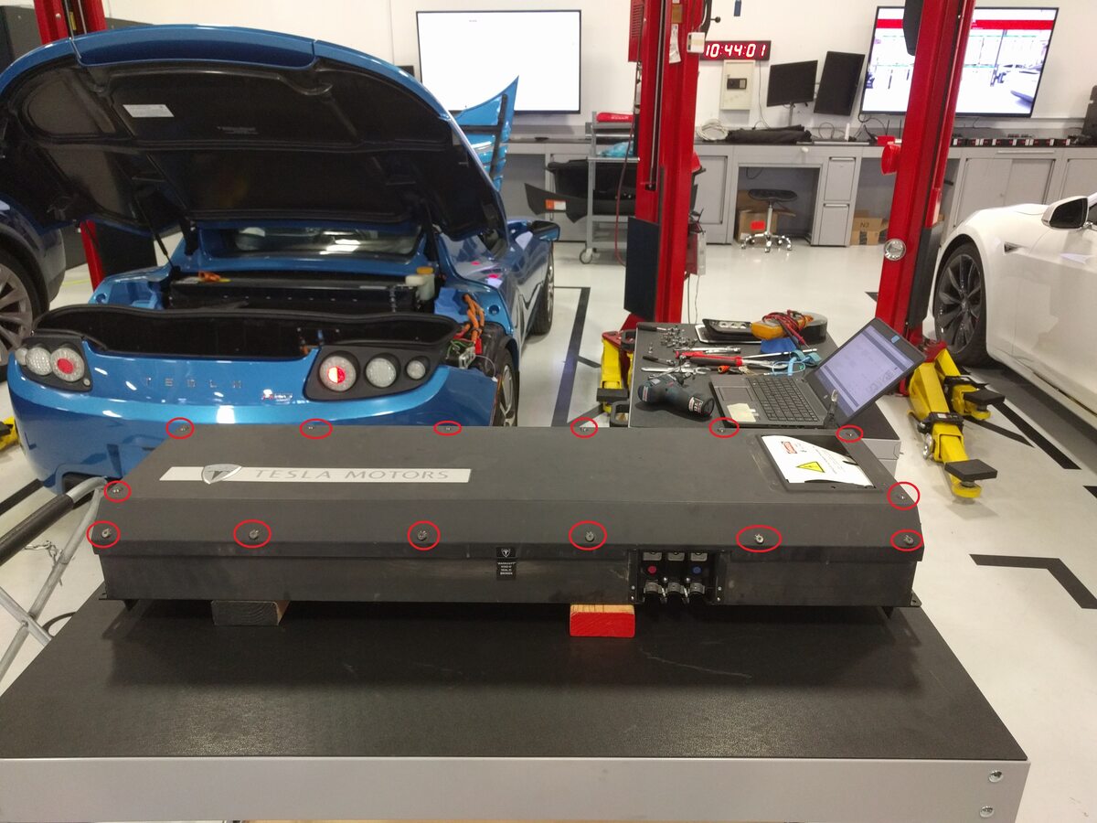
- Remove the PEM cover.
-
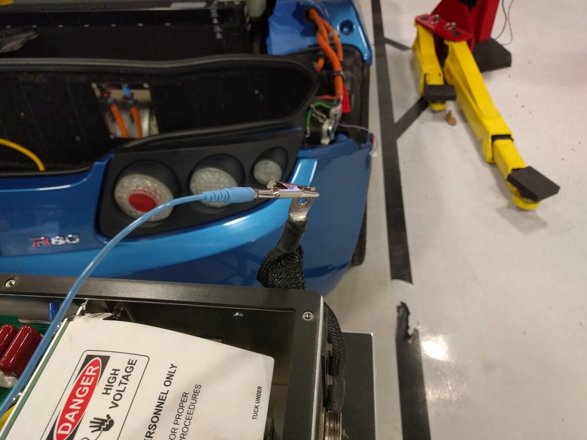
Attach the ESD ground strap to the PEM ground stud.
-
Set the multimeter to read Ohms.
WarningIf any of the following voltage readings are not within specification, contact Service Engineering before performing any further voltage checks.
-
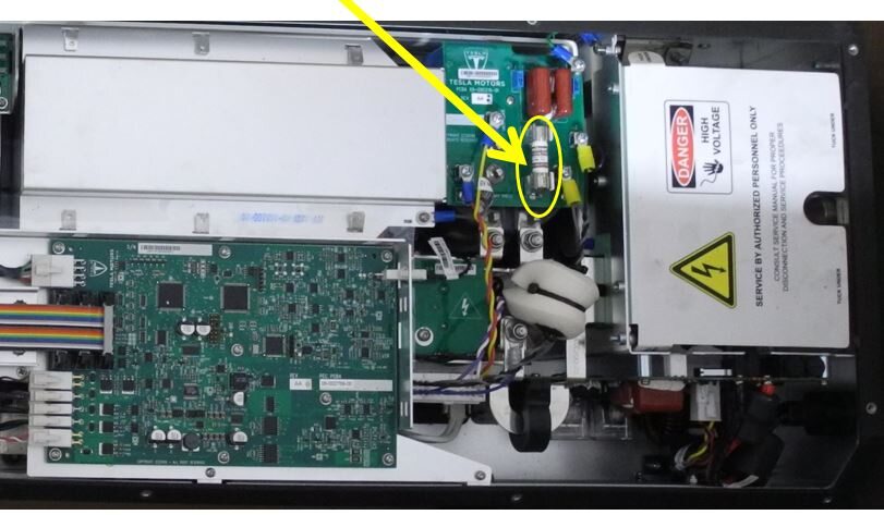
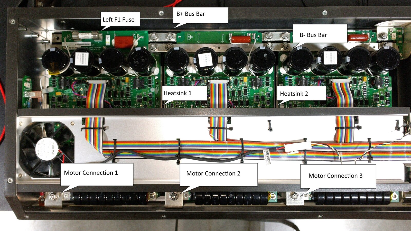
Check reading for B+ to B- bus bar.
NotePositive lead on B+, Negative lead on B-. Starts low and ramps to ~.715MΩ.
-
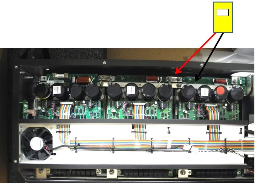
Check right F1 Fuse.
NoteLeads on both ends of fuse. Target = 0Ω - 0.2Ω.
-
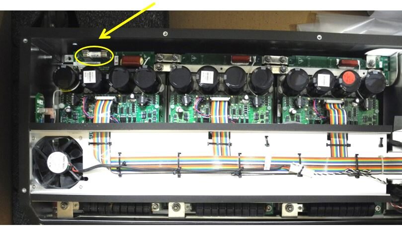
Check left F1 Fuse.
NoteLeads on both ends of fuse. Target = 0Ω - 0.2Ω.
-
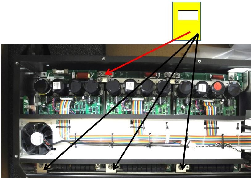
Check B+ to Motor 1.
NotePositive lead on B+ bus bar. Resistance ramps up to high MΩ.
-
Check B+ to Motor 2.
NotePositive lead on B+ bus bar. Resistance ramps up to high MΩ.
-
Check B+ to Motor 3.
NotePositive lead on B+ bus bar. Resistance ramps up to high MΩ.
-
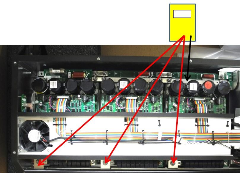
Check B- to Motor 1.
NotePositive lead on B- bus bar. Resistance ramps up to high MΩ.
-
Check B- to Motor 2.
NotePositive lead on B- bus bar. Resistance ramps up to high MΩ.
-
Check B- to Motor 3.
NotePositive lead on B- bus bar. Resistance ramps up to high MΩ.
-
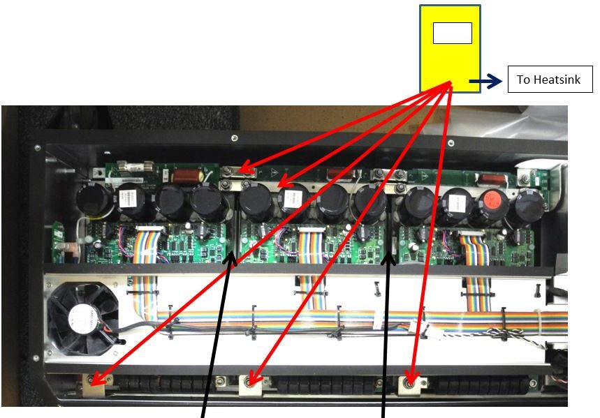
Check B+ to heatsink 1.
NoteNegative lead on heatsink screw. Resistance ramps up to very high MΩ.
-
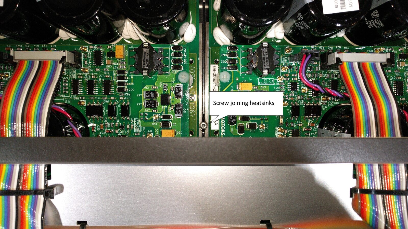
Check GND reference, PCBA to Heatsink 1.
NoteTarget = 0Ω - 0.2Ω. If not, check heatsink screw for proper torque (1.5 Nm).
-
Check B- to heatsink 1.
NoteNegative lead on heatsink screw. Resistance ramps up to very high MΩ.
-
Check Motor 1 to heatsink 1.
NoteNegative lead on heatsink screw. Resistance ramps up to very high MΩ.
-
Check Motor 2 to heatsink 1.
NoteNegative lead on heatsink screw. Resistance ramps up to very high MΩ.
-
Check Motor 3 to heatsink 1.
NoteNegative lead on heatsink screw. Resistance ramps up to very high MΩ.
-
Install the PEM cover and screws (x14) (torque 1.5 Nm).

- Install the PEM. See Power Electronics Module (PEM) - Roadster 2.x.