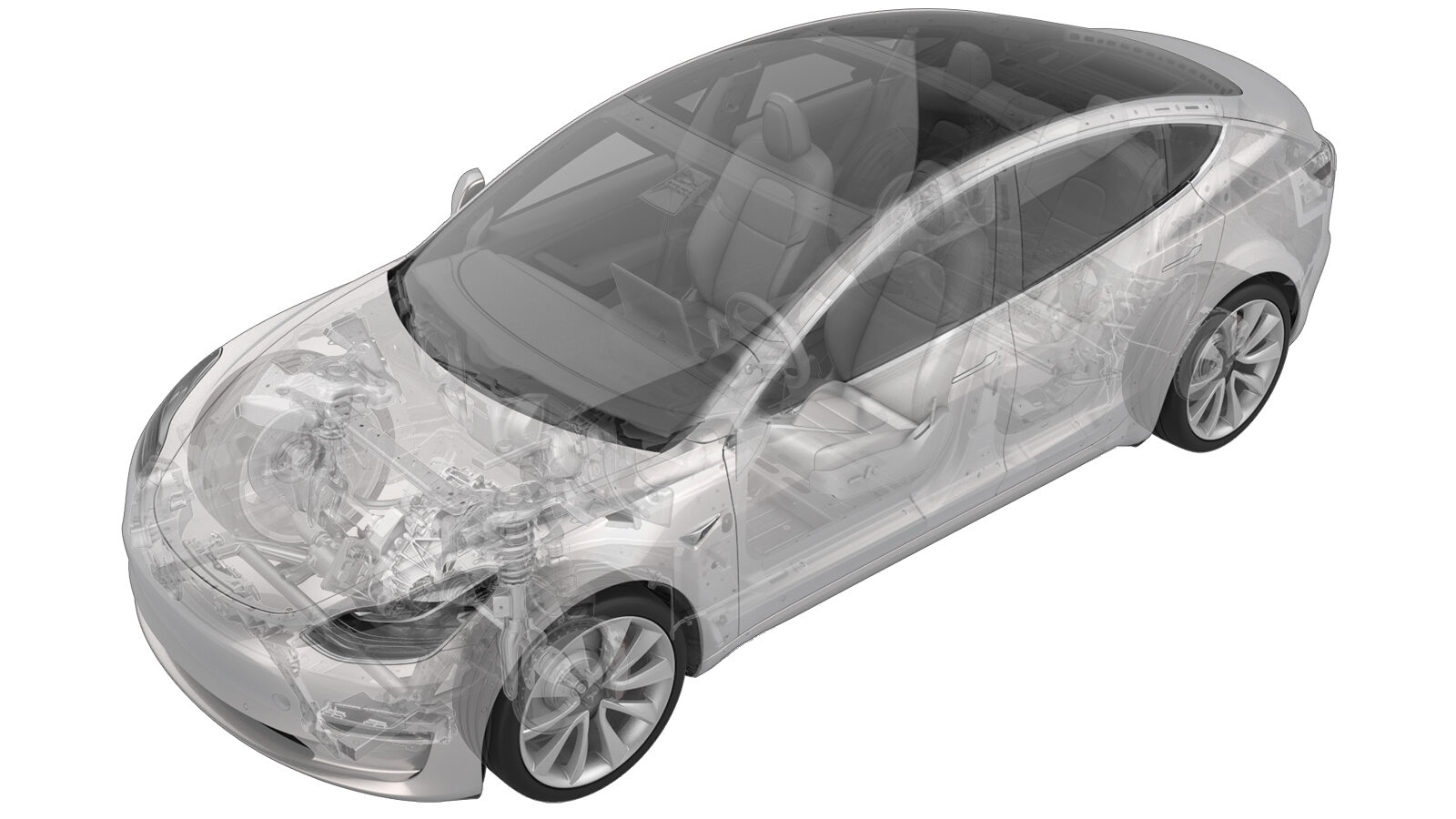
Módulo - Sistema de sujeción (bomba de calor) (Desinstalación y sustitución)
 Código de corrección
20015012 0.42
NOTA: Salvo que se indique lo contrario explícitamente en el procedimiento, el código de corrección anterior y el FRT reflejan todo el trabajo necesario para realizar este procedimiento, incluidos los procedimientos vinculados. No acumule códigos de corrección a menos que se le indique explícitamente que lo haga.
NOTA: Consulte Tiempos de tarifa plana (FRT) para obtener más información sobre los FRT y cómo se crean. Para enviar sus comentarios sobre los valores de FRT, escriba a ServiceManualFeedback@tesla.com.
NOTA: Consulte Protección personal para asegurarse de llevar el EPI adecuado al realizar el siguiente procedimiento. Consulte Precauciones ergonómicas para ver prácticas de trabajo seguras.
- 2026-01-30: Added steps to disarm the restraint control module.
- 2024-05-14: Replaced Toolbox 3 routines by routines using the touchscreen.
- 2024-04-18: Eliminated redundant ODIN routine and refined instructions on headlight adjustment.
- 2023-10-20: Added step to aim the headlights.
- 2023-09-26: Updated links to Center Console 2.0 (Remove and Install).
- 2023-08-24: Added additional warning to make sure LV is disconnected.
- 2023-09-05: Updated the Toolbox routine steps.
Retirar
-
Open all the doors and lower the windows.
NotaIf the vehicle is being powered down, latch the rear doors to prevent accidental closure.
- Enable Service Mode Plus. See Modo Servicio Plus.
-
En la pantalla táctil, toque , toque Ejecutar y deje que finalice la rutina.
NotaAsegúrese de que los airbags estén desactivados después de completar la rutina.
Se muestra el Model Y; los demás modelos son similares
- Open the hood.
-
Remove the center console assembly from the vehicle. See Consola central (2.0) (Desinstalación e instalación).
AvisoAsegúrese de que la baja tensión está desconectada antes de continuar con el siguiente paso.
-
Release the locking tabs, release the connector levers, and disconnect the restraint control module connectors (x2).
-
Remove and discard the nuts (x3) that attach the restraint control module to the vehicle, and then remove the module from the vehicle.
NotaSe recomienda utilizar las siguientes herramientas:
- Vaso de 10 mm
Instalar
-
Position the restraint control module into vehicle, and then install new nuts (x3) that attach the module to the vehicle.
 8 Nm (5.9 lbs-ft)NotaVerify that the part number on the new module is correct.TIpSe recomienda utilizar las siguientes herramientas:
- Vaso de 10 mm
-
Connect the restraint control module connectors (x2), and then engage the locking levers and connector locks.
- Install the center console assembly into the vehicle. See Consola central (2.0) (Desinstalación e instalación).
- Reinstall the vehicle software. See Reinstalación de software - Pantalla táctil.
- Entre al Modo Servicio Plus. Consultar Modo Servicio Plus
-
En la pantalla táctil, toque .
-
En la siguiente pantalla, toque Ejecutar y deje que finalice la rutina.
-
On the touchscreen, check the headlight leveling system.
- If the headlight leveling system is "Ride Height Sensor", exit Service Mode, see Modo de servicio, and discontinue this procedure.
- If the headlight leveling system is "Virtual Pitch Sensor", exit Service Mode, see Modo de servicio, and continue to the next step.
- Adjust the headlights: