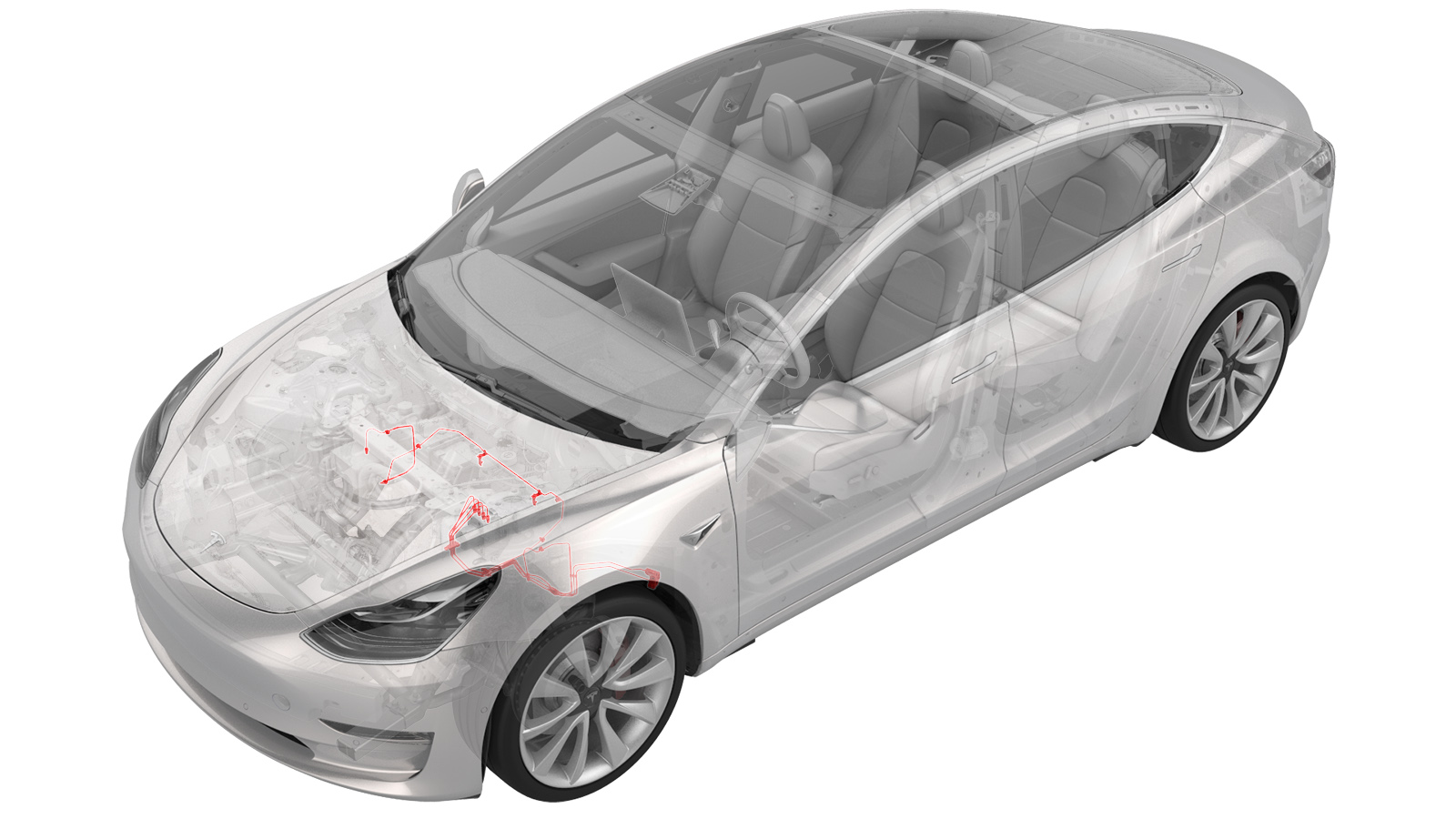
Latiguillos de freno - Conjunto de 4 tubos - ABS a ruedas (Motor dual) (Desinstalación y sustitución)
 Código de corrección
330339524.62
NOTA: Salvo que se indique lo contrario explícitamente en el procedimiento, el código de corrección anterior y el FRT reflejan todo el trabajo necesario para realizar este procedimiento, incluidos los procedimientos vinculados. No acumule códigos de corrección a menos que se le indique explícitamente que lo haga.
NOTA: Consulte Tiempos de tarifa plana (FRT) para obtener más información sobre los FRT y cómo se crean. Para enviar sus comentarios sobre los valores de FRT, escriba a ServiceManualFeedback@tesla.com.
NOTA: Consulte Protección personal para asegurarse de llevar el EPI adecuado al realizar el siguiente procedimiento. Consulte Precauciones ergonómicas para ver prácticas de trabajo seguras.
El líquido de frenos disuelve la pintura. Tenga trapos limpios y abundante agua cerca para limpiar el líquido de frenos en caso de que se derrame sobre superficies pintadas.
Deseche el líquido de frenos usado de acuerdo con las normas medioambientales locales.
- Remove the front subframe. See Conjunto del bastidor auxiliar - Parte delantera (motor dual) (Desinstalación e instalación).
- Remove the 12V battery bracket. See Soporte - Batería de 12 V (motor dual) (Desinstalación y sustitución).
-
Remove the bolts (x2) that attach the ground leads (G098 and G099) to the LH side of the body.
NotaDiscard thread-cutting tri-lobular bolts after removal. If equipped with new bolts (1447438-00-A), the bolts can be reused.
-
Release the white harness clip from the body.
-
Release the black harness clip from the body.
-
Remove the front harness clip from the LH frame rail area.
-
Disconnect the ground connector (G011) from the LH frame rail area.
-
Move the LH side of the front harness aside for access.
-
Disconnect the ABS modulator connector.
NotaDisengage locking tab and pull up on the connector to release.
-
Release the front harness clips (x2) at the LH frame rail area.
- Coloque un recipiente de drenaje de aceite debajo de la unidad del ABS.
-
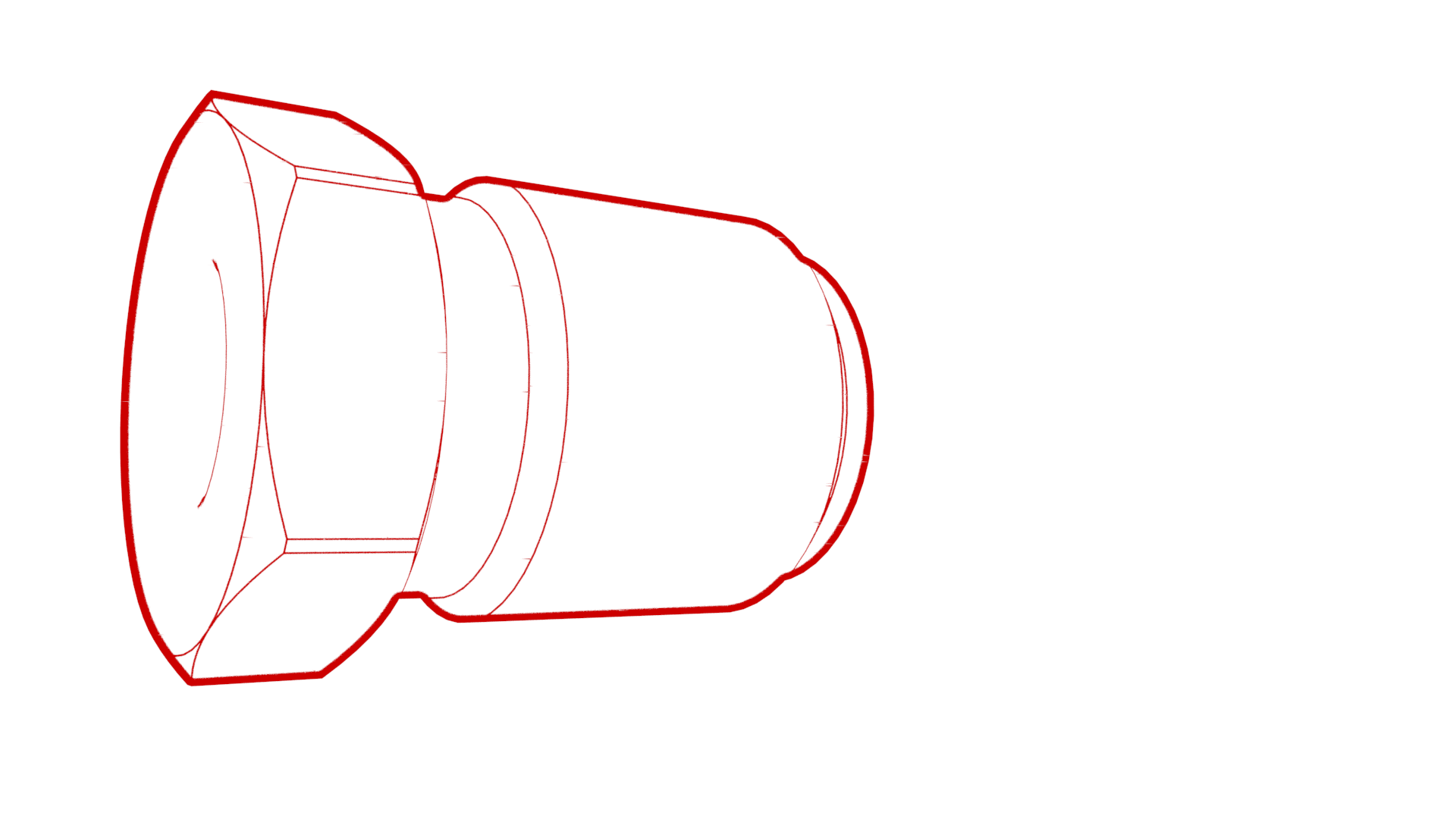
Retire las tuercas de los tubos de los latiguillos de freno de la unidad del ABS y deje que el líquido salga.
-
Remove the front brake line bundle clip at the LH front rail area.
-
Remove the RH front brake line from the front brake line bundle clip at the LH front rail area.
- Remove the oil drain container from underneath the vehicle.
- Partially raise the vehicle.
-
Remove the thermal beam hose clips (x2) from the body.
- Coloque un recipiente de drenaje de aceite debajo del bloque de conexiones de los latiguillos de freno delanteros.
-
Retire las tuercas de los tubos de los latiguillos de freno del bloque de conexiones y deje que el líquido salga.
-
Remove the black clip from the LH front junction block.
-
Release the brake lines from the LH front junction block.
- Coloque el recipiente de drenaje de aceite debajo de la manguera del freno delantero izquierdo.
-
Quite de la manguera del freno la tuerca del tubo del latiguillo del freno, en el soporte del latiguillo, y deje que el líquido salga.
-
Remove the LH front brake line clip from the body.
- Coloque el recipiente de drenaje de aceite debajo de la manguera del freno delantero derecho.
-
Quite de la manguera del freno la tuerca del tubo del latiguillo del freno, en el soporte del latiguillo, y deje que el líquido salga.
-
Remove the RH front brake line clips (x2) from the body.
- Fully raise the vehicle.
-
Release the coolant hose clip on the LH fender.
-
Remove the front brake line bundle clip from the LH body rail area.
-
Remove the LH front side 3 bundle brake lines from the vehicle.
NotaRoute the front brake line bundle out of steering column area, then route it through LH front wheel liner and front subframe area.
-
Release the clips (x3) that attach the 12V harness to the body.
-
Release the clips (x7) that attach the HV cables to the body.
-
Release the clips (x2) that attach the coolant manifold line from the body.
-
Release the clips (x4) that attach the coolant hoses to the body.
-
Release the clip that attaches the coolant hose to the RH side of the body.
-
Remove the clips (x5) that attach the RH front brake line to the body.
-
Remove the RH front brake line from the vehicle.
NotaRoute the brake line out of steering column area, then move it towards the RH side, and the remove it out between the front subframe area.
Instalar
- Remove the RH front brake line from the new front 4 tube brake bundle.
-
Position the RH front brake line to vehicle for installation.
NotaRoute the RH front brake line through the front subframe area out toward the RH front wheel liner area, then route it to LH frame rail area.
-
Install the clips (x5) that attach the RH front brake line to the body.
-
Install the clip that attaches the RH side coolant hose to the body.
-
Install the clips (x4) that attach the coolant hoses to the body.
-
Install the clips (x2) that attach the coolant manifold line to the body.
-
Install the clips (x7) that attach the HV cables to the body.
-
Install the clips (x3) that attach the 12V harness to the body.
-
Install the left side 3 tube bundle to the vehicle.
NotaRoute the brake line bundle through the LH front wheel liner and front subframe area, then route it to LH frame rail area.
-
Install the clip that attaches the coolant hose to the LH fender.
-
Install the clip that attaches the front brake line bundle to LH body rail area.
- Partially lower the vehicle.
-
Install the RH front brake line into the brake hose at the jounce hose bracket, and then use a crowfoot extension to install the brake line tube nut into the brake hose.
 16 Nm (11.8 lbs-ft)
 -
Install the RH front brake line clips (2) to the body.
-
Inserte el latiguillo del freno en la manguera del freno, en el soporte del latiguillo; a continuación, utilice una extensión para llaves de pata de cabra para instalar la tuerca del tubo del latiguillo de freno en la manguera del freno.
 16 Nm (11.8 lbs-ft)
 -
Install the clip that attaches the LH front brake line clip to body
Nota1x clip
-
Install the brake lines into the LH front junction block.
-
Install the clip that secures the brake lines at the LH front junction block.
-
Use a crowfoot extension to install the brake line tube nuts into the junction block.
 16 Nm (11.8 lbs-ft)
 -
Install the thermal beam hose clips (x2) to the body.
- Lower the vehicle.
-
Install the RH front brake line to front brake line bundle clip at the LH front rail area.
-
Install the front brake line bundle clip at the LH front rail area.
-
Install the master cylinder brake lines to the 4 tube bundle clip.
-
Inserte los latiguillos de freno en la unidad del ABS; a continuación, utilice una extensión para llaves de pata de cabra para instalar las tuercas de los tubos de los latiguillos de freno en la unidad del ABS.
 16 Nm (11.8 lbs-ft)
 -
Re-position the LH side of the front harness to the LH frame rail for installation.
-
Install the front harness clips (x2) at the LH frame rail area.
-
Connect the LH frame rail ground connector (G011).
-
Install the front harness clip to the LH frame rail area.
-
Install the white harness clip to the left front fender.
-
Install the black harness clip to the left front fender.
-
Install the bolts (x2) that attach the grounds leads (G098 and G099) to the body (torque 10 Nm).
NotaInstall new bolts if thread-cutting tri-lobular bolts were installed previously. Hand-start bolts at least 6 rotations before applying torque to avoid damaging the weld nut.
-
Install the ABS modulator connector
NotaGently push connector downward, then engage locking tab
- Reinstall the 12V battery bracket. See Soporte - Batería de 12 V (motor dual) (Desinstalación y sustitución).
- Install the 12V battery into the vehicle. See Batería de 12 V/baja tensión (Desinstalación y sustitución).
- Install the front subframe. See Conjunto del bastidor auxiliar - Parte delantera (motor dual) (Desinstalación e instalación).
- Connect 12V power. See Alimentación de 12 V/baja tensión (Desconexión y conexión).
- Remove the HVAC plenum outer duct. See Cámara - Entrada - HVAC (Desinstalación y sustitución).
- Perform a coolant air purge. See Sistema de refrigeración (llenado parcial y purga).
- Bleed the brakes. See Purga/limpieza del líquido de frenos.
- Install the underhood storage unit. See Unidad de almacenamiento del vano del motor (Desinstalación y sustitución).
- Install the HVAC plenum outer duct. See Cámara - Entrada - HVAC (Desinstalación y sustitución).
- Install the rear underhood apron. See Faldón del vano del motor - Parte trasera (Desinstalación y sustitución).
- Install the front aero shield. See Panel - Deflector aerodinámico - Delantero (Desinstalación y sustitución).
- Install the LH and RH wheel liner. See Revestimiento del paso de la rueda - Parte delantera - Lado izquierdo (Desinstalación y sustitución).
- Install all wheels. See Conjunto de rueda (Desinstalación e instalación).
- Torque the LH and RH front halfshaft nuts to 300 Nm.
- Perform a 4-wheel alignment check. See Comprobación de la alineación de las cuatro ruedas.