2026-09-08
Drive Unit - Rear (4DU) (Structural Pack) (Remove and Install)
 Korrigeringskode
40011021
FRT
3.78
MERK: Hvis ikke noe annet er uttrykkelig oppgitt i prosedyren, gjenspeiler korrigeringskoden og dens tilhørende FRT alt arbeidet som kreves for å gjennomføre denne prosedyren, inkludert de tilknyttede prosedyrene. Ikke stable korrigeringskoder med mindre du bli uttrykkelig bedt om det.
MERK: Se Flat rate-tider for mer informasjon om FRT-er og hvordan de lages.
MERK: Se Personlig beskyttelse for å forsikre deg om at du bruker riktig PVU når du gjennomfører prosedyren nedenfor.
MERK: Se Forholdsregler for ergonomi for trygge og sunne arbeidspraksiser.
Korrigeringskode
40011021
FRT
3.78
MERK: Hvis ikke noe annet er uttrykkelig oppgitt i prosedyren, gjenspeiler korrigeringskoden og dens tilhørende FRT alt arbeidet som kreves for å gjennomføre denne prosedyren, inkludert de tilknyttede prosedyrene. Ikke stable korrigeringskoder med mindre du bli uttrykkelig bedt om det.
MERK: Se Flat rate-tider for mer informasjon om FRT-er og hvordan de lages.
MERK: Se Personlig beskyttelse for å forsikre deg om at du bruker riktig PVU når du gjennomfører prosedyren nedenfor.
MERK: Se Forholdsregler for ergonomi for trygge og sunne arbeidspraksiser.
- 2026-09-01: Released new procedure.
ADVARSEL
Denne prosedyren er et UTKAST. Selv om den har blitt godkjent, kan det hende at advarsler og forholdsregler mangler. Følg sikkerhetskravene, og vær ytterst forsiktig ved arbeid på eller nær høyspenningssystemer og -komponenter.
Fjerne
- Position the vehicle behind the lift, ensuring all four doors have enough clearance to open fully, and lower all four windows.
- While performing the courtesy inspection, note any abnormal tire wear that could indicate the need for an alignment.
- Remove the RH rocker panel carrier. See Holder – kanalpanel – venstre (Strukturell pakke) (fjerne og skifte ut).
- Raise and support the vehicle. See Heve bil – løftebukk med 2 stolper.
- Remove the LH and RH rear wheel caps. See Hjulenhet (fjerne og skifte ut).
- Loosen the LH and RH rear wheel lug nuts.
- Enable Service Mode Plus. See Servicemodus Pluss.
- On the touchscreen, touch , and allow the routine to complete.
-
On the touchscreen, touch , and choose Both under EPB Selection and Start under Action Selection, then touch Runand allow the routine to complete.
ADVARSELThe vehicle can slide freely. Maintain braking during the routine.
- Disconnect the LV power. See 12 V-/lavspenningsstrøm (koble fra og koble til).
- Raise the vehicle partially and lower the lift onto locks.
- Remove the LH and RH rear wheels. See Hjulenhet (fjerne og skifte ut).
- Raise the vehicle fully and lower the lift onto locks.
- Remove the rear aero shield panel. See Panel – luftskjerm – bakre (fjerne og skifte ut).
- Perform the vehicle HV disablement procedure. See Deaktiveringsprosedyre for bilens høyspenning (Strukturell pakke).
- Remove the LH and RH rear suspension covers. See Deksel – fjæring bak – venstre (fjerne og skifte ut).
-
Remove the clips that secure the LH and RH rear wheel liners to rear fascia assembly.
Figur 1. LH shown; RH similar Figur 2. LH shown; RH similar - Remove the rear diffuser. See Diffuser – bakfanger (fjerne og skifte ut).
- Lower the vehicle partially and set onto locks.
-
Remove the nut that attaches the rear drive unit ground strap to the body, and then remove the ground strap from the body.
MerkUse of the following tool(s) is recommended:
- 10 mm deep socket
- Cordless Ratchet/Impact Driver
-
Remove and discard the bolts (x2) that attach the LH rear brake caliper to the LH rear knuckle, remove the caliper from the knuckle, and then hang the caliper from an S-hook.
MerkUse of the following tool(s) is recommended:
- External Torx E18
- Cordless Ratchet/Impact Driver
- 3 in extension
-
Install the spring compressor onto the LH rear coil spring, and slightly compress the spring to take the load off of the suspension.
MerkRefer to the Tooling Profile for additional information.
-
Remove the bolts (x2) that attach the LH rear strut to the body at the LH top mount.
- Repeat step 21 through step 23 on the RH side of the vehicle.
- Raise the vehicle fully and lower the lift onto locks.
-
Release the red locking tab and then disconnect the electrical harness from the rear subframe harness RH connector.
-
Release the clip that attaches the rear subframe harness to the body on the RH side.
-
Release the red locking tab and then disconnect the electrical harness from the rear subframe harness LH connector.
-
Release the clip that attaches the rear subframe harness to the body on the LH side.
-
Remove and discard the nut that attaches the LH rear stabilizer bar end link to the rear stabilizer bar.
MerkUse of the following tool(s) is recommended:
- 15 mm socket
- Ratchet/torque wrench
- Flex head ratchet/flex head torque wrench
MerkUse a 5mm allen wrench to prevent the ball joint stud from turning and damaging the ball joint. -
Remove LH rear stabilizer bar end link from the rear stabilizer bar.
MerkMove the stabilizer bar up and down to ease removal of the end link.
-
Remove and discard the nut that attaches the RH rear stabilizer bar end link to the rear stabilizer bar.
MerkUse of the following tool(s) is recommended:
- 15 mm socket
- Ratchet/torque wrench
- Flex head ratchet/flex head torque wrench
MerkUse a 5mm allen wrench to prevent the ball joint stud from turning and damaging the ball joint. -
Remove RH rear stabilizer bar end link from the rear stabilizer bar.
MerkMove the stabilizer bar up and down to ease removal of the end link.
-
Remove and discard the bolts (x4) that attach the rear stabilizer bar to the rear subframe, and then remove the stabilizer bar from the subframe.
MerkUse of the following tool(s) is recommended:
- 11 mm socket
- 3 in extension
- Ratchet/torque wrench
-
Position a coolant drain collector underneath the LH rear of the HV battery.
-
Remove the RDU inverter inlet hose by rotating it between the subframe and battery out of the vehicle, then plug the hose connections as needed.
Merk1x spring clip, 1x clip
-
Position the coolant drain container underneath the LH RDU area.
-
Disconnect the RDU inverter inlet hose from the fluid coupling, allow the coolant to drain from the inverter, then plug the ends as needed.
-
Release the RDU inverter hose clip from the RDU HV cable harness.
-
Remove the RDU inverter inlet hose from between the subframe and the drive unit.
-
Position a coolant drain collector underneath the RH rear of the HV battery.
-
Disconnect the RDU oil cooler outlet pipe and plug the hose connections as needed.
-
Remove the coolant drain collector from under the vehicle.
-
Release the locking tab, push the handle downward, and then disconnect the rear subframe electrical harness from the rear drive unit inverter logic connector.
ADVARSELOnce disconnected, make sure that coolant does not get into the connectors.
-
Release the clip that attaches the rear subframe electrical harness to the rear drive unit inverter.
-
Remove the bolt that attaches the rear drive unit HV harness bracket to the rear drive unit inverter.
MerkUse of the following tool(s) is recommended:
- 10 mm socket
- Ratchet/torque wrench
- Remove all items from pockets and ensure not wearing metal items.
- Put on HV insulating gloves and leather over gloves.
-
Slide the locking tab, raise the black handle, disconnect the rear drive unit HV harness from the rear drive unit inverter HV header,and then set the HV harness aside.
-
Remove the nut(s) that attach(es) the rear drive unit HV harness bracket to the HV battery.
-
Slide the red locking tab, raise the black handle, and then disconnect the rear drive unit HV harness from the HV battery header.
-
Remove the rear drive unit HV harness down and out from between the rear subframe and the HV battery.
MerkRotate the harness as it is removed to allow access for the bracket.
- Remove leather over gloves and HV insulating gloves.
-
Position the subframe lifting tool under, and up against the rear subframe.
-
With the help of an assistant, fully secure the straps (x3) that attach the rear subframe to the subframe lifting tool.
-
Use a paint pen to trace around the LH and RH rear subframe mounting bolts, so that the bolts can be realigned later during the subframe installation.
-
Use a paint pen to apply a witness mark where the rear subframe contacts the body at the LH and RH rear subframe mounting bolts, so that the subframe can be realigned to the body later during subframe installation.
-
Remove the small bolts (x2) that attach the LH shear plate to the HV battery.
MerkUse of the following tool(s) is recommended:
- Ratchet/torque wrench
- 3 in extension
- 13 mm socket
-
Remove the large bolt that attaches the LH shear plate and rear subframe to the body, and then remove shear plate.
-
Remove the small bolts (x2) that attach the RH shear plate to the HV battery.
- Ratchet/torque wrench
- 3 in extension
- 13 mm socket
-
Remove the large bolt that attaches the RH shear plate and rear subframe to the body, and then remove shear plate.
-
Remove and discard the LH and RH rear subframe bolts that attache the subframe to the body.
Figur 3. LH shown; RH similar -
Lower the subframe lifting tool to remove the subframe assembly and the rear drive unit from the vehicle.
ADVARSELDo not damage hoses or harnesses while lowering the subframe.
-
Disconnect the air supply from the subframe lifting tool.
-
Move the subframe lifting tool and the subframe away from vehicle.
MerkRaise the vehicle if necessary.
-
Release the clip that attaches the rear drive unit ground strap to the rear subframe.
-
Remove the bolt that attaches the rear drive unit ground strap to the rear drive unit, and then remove the ground strap from the drive unit.
MerkUse of the following tool(s) is recommended:
- 10 mm socket
- 4 in extension
- Cordless 1/4in Dr Ratchet
-
Position a coolant catcher under the RH side of the subframe and rear drive unit assembly, and position a foldable funnel to direct coolant drain from the heat exchanger.
-
Release the clip, disconnect the rear drive unit coolant outlet hose from the rear drive unit heat exchanger, and allow the heat exchanger and hose to drain.
-
Release clips (x3) that attach the rear drive unit coolant outlet hose to rear drive unit, and then manuever the hose out from between the drive unit and rear subframe.
-
Release the clips (x2) that attach the rear drive unit inverter outlet to heat exchanger hose to the rear drive unit.
-
Cut the rear drive unit inverter NVH cover at the line indicated so as to access the clip for the rear drive unit inverter to heat exchanger hose.
MerkOpen the cut in the NVH cover, but be carefull not to remove any of the cover in doing so.
-
Release the clip, disconnect the rear drive unit inverter to heat exchanger hose from the rear drive unit inverter outlet, and allow to drain.
-
Release the clip, disconnect the rear drive unit inverter to heat exchanger hose from the rear drive unit heat exchanger, and allow to drain.
-
Release the remaining clips (x2) that attach the rear drive unit inverter outlet to heat exchanger hose to the rear drive unit, and then manuever the hose out from between the drive unit and rear subframe.
-
Pull the red tab to release, and then pull the red tab again to disconnect the rear subframe harness from the oil pump connector.
-
Pull the red tab to release, pull the red tab again to disconnect the rear subframe harness from the resolver connector, and then release the clips (x2) that attach the subframe harness to the rear drive unit.
-
Remove the bolt that attaches the LH rear wheel speed sensor to LH rear knuckle, and then remove the sensor from the knuckle.
MerkUse of the following tool(s) is recommended:
- 10 mm socket
- Ratchet/torque wrench
- 4 in extension
-
Release the grommet that attaches the LH rear wheel speed sensor harness to LH rear knuckle.
-
Remove the nut and bolt that attach the LH rear upper aft link to the LH rear knuckle.
-
Remove the nut and bolt that attach the LH rear upper fore link to the LH rear knuckle.
-
Remove the nut and bolt that attach the LH rear toe link to the LH rear knuckle.
-
Loosen, but do not remove, the nut and bolt that attach the LH rear lower fore link to the LH rear knuckle.
-
Position the axle remover cable around the inner joint of the LH rear drive unit halfshaft, and then use the U-bolt to hold the axle remover cable in position.
-
Hook the axle remover slide hammer onto the 2 axle remover cable loops, and then use the slide hammer to remove the LH halfshaft from the rear drive unit.
MerkBe carefull not to damage the halfshaft boots and drive unit seals when separating the halfshaft from the drive unit.
- Repeat step 78 through step 85 on the RH side of the rear subframe assembly.
-
Position the rear subframe assembly under the gantry.
-
Use the shackles (x3) to attach the drive unit sling tool to the rear drive unit.
-
Attach the drive unit sling tool to the gantry.
-
Use the gantry to raise the drive unit sling tool so that there is slight tension in the cables.
-
Remove the bolt that attaches the rear drive unit to the LH side of the rear subframe.
MerkUse of the following tool(s) is recommended:
- 18 mm socket
- Cordless 3/8in Dr Impact
-
Remove the bolt that attaches the rear drive unit to the RH side of the rear subframe.
MerkUse of the following tool(s) is recommended:
- 18 mm socket
- Cordless 3/8in Dr Impact
-
Remove the bolt that attaches the rear drive unit to the rear of the rear subframe.
MerkUse of the following tool(s) is recommended:
- 18 mm socket
- Cordless 3/8in Dr Impact
-
With the help of an assistant, use the gantry to raise the rear drive unit sling tool, guide halfshafts away from the rear drive unit, and separate the rear drive unit up from the rear subframe.
-
Move the rear subframe and subframe lift out from underneath the rear drive unit, and then lower the rear drive unit onto a protected surface.
Montere
-
Lift the rear drive unit off of the protective surface and position the rear subframe and subframe lift underneath the drive unit.
-
With the help of an assistant, use the gantry to lower the rear drive unit sling tool, guide halfshafts into the rear drive unit, and lower the rear drive unit into the rear subframe.
-
Lower the rear drive unit sling tool so as to install and hand tighten the bolt that attaches the rear drive unit to the rear of the rear subframe.
-
Install and hand tighten the bolt that attaches the rear drive unit to the RH side of the rear subframe.
-
Install and hand tighten the bolt that attaches the rear drive unit to the LH side of the rear subframe.
-
Lower the drive unit sling tool to release tension in the cables, and then remove the sling tool from the rear drive unit.
-
Remove the drive unit sling tool from the gantry.
-
Tighten the rear drive unit mount bolts (x3).
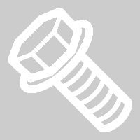 80 Nm (59.0 lbs-ft)MerkUse of the following tool(s) is recommended:
- 18 mm socket
- Flex head ratchet/flex head torque wrench
-
With the help of an assistant, slightly rotate the LH halfshaft so as to align the splines of the halfshaft to those in the rear drive unit, lift up on the LH rear knuckle to help move the halfshaft into the drive unit, and then apply force to seat the halfshaft in the drive unit.
MerkIf the halfshaft binds, back the halfshaft out, rotate it slightly, and try again.ADVARSELWhen installing the halfshaft(s) into the drive unit:
- Påse at åpningen til sprengringen vender mot bunnen på drivenheten.
- Ikke skad eller forskyv oljetetningen.
- Verifiser at halvakselen sitter som den skal:
- Skyv forsiktig halvakselen inn i drivenheten til du hører et klikk fra halvakseltappen som inneholder pinjongakselen.
- Du vil føle at det trekker litt på halvakselen når seegerringen til halvakselen låses på plass.
- Trekk på den indre halvakselskålen for å bekrefte at seegerringen er låst på plass. Hvis halvakselen løsner fra drivenheten, monterer du halvakselen på nytt og tester deretter at den sitter som den skal.
-
Install the LH rear toe link to the LH rear knuckle, and then install and hand-tighten the nut and bolt that attach the link to the knuckle.
-
Install the LH rear upper fore link to the LH rear knuckle, and then install and hand-tighten the nut and bolt that attach the link to the knuckle.
-
Install the LH rear upper aft link to the LH rear knuckle, and then install and hand-tighten the nut and bolt that attach the link to the knuckle.
-
Fasten the grommet that attaches the LH rear wheel speed sensor harness to LH rear knuckle.
-
Install the LH rear wheel speed sensor to LH rear knuckle, and then install the bolt that attaches the sensor to knuckle.5 Nm (3.7 lbs-ft)
- Repeat step 9 through step 14 on the RH side of the rear subframe assembly.
-
Connect the rear subframe harness to the resolver connector, push the red tab to secure, and then fasten the clips (x2) that attach the subframe harness to the rear drive unit.
-
Connect the rear subframe harness to the oil pump connector, and then push the red tab to secure.
-
Manuever the rear drive unit inverter outlet to heat exchanger hose in between the rear drive unit and rear subframe, and then fasten the clips (x2) that attach the hose to the drive unit.
-
Connect the rear drive unit inverter to heat exchanger hose to the rear drive unit heat exchanger, fasten the clip, and then perform a Push-Pull-Push check of the fitting.
-
Connect the rear drive unit inverter to heat exchanger hose to the rear drive unit inverter outlet, fasten the clip, and then perform a Push-Pull-Push check of the fitting.
-
Fasten the clips (x2) that attach the rear drive unit inverter outlet to heat exchanger hose to the rear drive unit.
-
Manuever the rear drive unit coolant outlet hose in between the rear drive unit and rear subframe, and then fasten the clips (x3) that attach the hose to drive unit.
-
Connect the rear drive unit coolant outlet hose to the rear drive unit heat exchanger, fasten the clip, and then perform a Push-Pull-Push check of the fitting.
-
Install the rear drive unit ground strap to the rear drive unit, and then install the bolt that attaches the ground strap to the drive unit.6 Nm (4.4 lbs-ft)MerkUse of the following tool(s) is recommended:
- 10 mm socket
- 4 in extension
- Ratchet/torque wrench
-
Fasten the clip that attaches the rear drive unit ground strap to the rear subframe.
-
Position the rear subframe and rear drive unit assembly under the vehicle.
-
Connect the air supply to the subframe lifting tool.
-
Carefully raise the subframe and rear drive unit assembly until they are up against the body.
ADVARSELDo not damage hoses or harnesses while raising the subframe.
-
Install and hand-tighten a new RH rear subframe bolt to attach the rear subframe to the body.
-
Install and hand-tighten a new LH rear subframe bolt to attach the rear subframe to the body.
-
Install the RH shear plate to the rear subframe, and then install a new large bolt to attach the RH shear plate and rear subframe to the body.
-
Install and hand-tighten the small bolts (x2) that attach the RH shear plate to the HV battery.
-
Install the LH shear plate to the rear subframe, and then install a new large bolt to attach the LH shear plate and rear subframe to the body.
-
Install and hand-tighten the small bolts (x2) that attach the LH shear plate to the HV battery.
-
Use a pry bar to shimmy the rear subframe with respect to the body, so that the subframe mounting bolts are centered in the tracings, and the witness marks align where the subframe contacts the body.
-
Tighten the RH rear subframe bolt that attaches the rear subframe to the body, and then mark the bolt after tightenting.160 Nm (118.0 lbs-ft)
-
Tighten the LH rear subframe bolt that attaches the rear subframe to the body, and then mark the bolt after tightenting.160 Nm (118.0 lbs-ft)
-
Tighten large bolt that attaches the LH shear plate and rear subframe to the body, and then mark the bolt after tightenting.130 Nm (95.9 lbs-ft)
-
Tighten large bolt that attaches the RH shear plate and rear subframe to the body, and then mark the bolt after tightenting.130 Nm (95.9 lbs-ft)
-
Tighten the small bolts (x2) that attach the RH shear plate to the HV battery.
35 Nm (25.8 lbs-ft)MerkSome vehicles are equipped with self-tapping bolts in bolt position #8-15 from the factory. If the vehicle is equipped with a bolt with a hexagonal indentation on the bolt head (1637725-00-A), the torque value is 64 Nm.
-
Tighten the small bolts (x2) that attach the LH shear plate to the HV battery.
35 Nm (25.8 lbs-ft)MerkSome vehicles are equipped with self-tapping bolts in bolt position #8-15 from the factory. If the vehicle is equipped with a bolt with a hexagonal indentation on the bolt head (1637725-00-A), the torque value is 64 Nm.
-
Release the straps (x3) that attach the rear subframe to the subframe lifting tool.
-
Lower the subframe lifting tool, and move it out from under the vehicle.
- Remove all items from pockets and ensure not wearing metal items.
- Put on HV insulating gloves and leather over gloves.
-
Install the rear drive unit HV harness in and up between the rear subframe and the HV battery.
MerkRotate the harness as it is installed to allow access for the bracket.
-
Verify that the black release lever of the rear drive unit HV harness connector is in the open position, install the connector flat and square to the HV battery header, secure the release lever to the closed position, and then slide the red connector locking tab.
-
Install the nut(s) that attach(es) the rear drive unit HV harness bracket to the HV battery.10 Nm (7.4 lbs-ft)
-
Verify that the black release lever of the rear drive unit HV harness connector is in the open position, install the connector flat and square to the rear drive unit inverter HV header, secure the release lever to the closed position, and then slide the connector locking tab.
- Remove leather over gloves and HV insulating gloves.
-
Install the bolt that attaches the rear drive unit HV harness bracket to the rear drive unit inverter.6 Nm (4.4 lbs-ft)
- Inspect the rear subframe electrical harness logic connector and the rear drive unit inverter logic connector for coolant, and use shop air and a clean dry shop towel to remove any coolant from the connectors.
-
Connect the rear subframe electrical harness to the rear drive unit inverter logic connector, raise the handle upward, and fasten the locking tab.
-
Fasten the clip that attaches the rear subframe electrical harness to the rear drive unit inverter.
-
Position a coolant drain collector underneath the LH rear of the HV battery.
-
Install the rear drive unit inverter inlet hose in and up between the rear subframe and the HV battery.
-
Fasten the clip that attaches the rear drive unit inverter inlet hose to rear drive unit HV harness.
-
Remove the plugs from the fittings, immediately connect the rear drive unit inverter inlet hose to the rear drive unit inverter, fasten the clip, and then perform a Push-Pull-Push check of the fitting.
-
Remove the plugs from the fittings, immediately connect the rear drive unit inverter inlet hose to the HV battery, fasten the clip, and then perform a Push-Pull-Push check of the fitting.
-
Position the coolant drain collector underneath the RH rear of the HV battery.
-
Connect the RDU oil cooler outlet pipe.
- Remove the coolant drain collector from under the vehicle.
-
Install the rear stabilizer bar to the rear subframe, and then install new bolts (x4) to attach the stabilizer bar to the subframe.30 Nm (22.1 lbs-ft)MerkUse of the following tool(s) is recommended:
- 11 mm socket
- 3 in extension
- Ratchet/torque wrench
-
Install the LH rear stabilizer bar end link into the rear stabilizer bar.
MerkMove the stabilizer bar up and down to ease installation of the end link.
-
Install a new nut to attach the LH rear stabilizer bar end link to the rear stabilizer bar and mark the bolt with a paint pen.55 Nm (40.6 lbs-ft)MerkUse a 5mm allen wrench to prevent the ball joint stud from turning and damaging the ball joint.
-
Install the RH rear stabilizer bar end link into the rear stabilizer bar.
MerkMove the stabilizer bar up and down to ease installation of the end link.
-
Install a new nut to attach the RH rear stabilizer bar end link to the rear stabilizer bar and mark the nut with a paint pen.55 Nm (40.6 lbs-ft)MerkUse a 5mm allen wrench to prevent the ball joint stud from turning and damaging the ball joint.
-
Fasten the clip that attaches the rear subframe harness to the body on the LH side.
-
Connect electrical harness to the rear subframe harness LH connector and then fasten the red locking tab.
-
Fasten the clip that attaches the rear subframe harness to the body on the RH side.
-
Connect electrical harness to the rear subframe harness RH connector and then fasten the red locking tab.
-
Install the rear drive unit ground strap to the body, and then install the nut that attaches the ground strap to the body.10 Nm (7.4 lbs-ft)
-
Install the LH rear strut to the body at the LH top mount, and then install the bolts (x2) that attach the strut to the body.41 Nm (30.2 lbs-ft)
-
Remove the S-Hook, install the LH rear brake caliper to the LH rear knuckle, and then install new bolts (x2) to attach the caliper to the knuckle.83 Nm (61.2 lbs-ft)
-
Remove the bolt that attaches the LH rear brake rotor to the hub.
-
Install the hub jack adapter onto the LH rear hub and hand-tighten the lug nuts (x5).
-
Use an underhoist stand to support the hub jack adapter and simulate the LH rear suspension at ride height.
-
Use the rear ride height torque gauge to verify the LH rear suspension is set to ride height specification.
MerkIt may be necessary to slightly adjust the underhoist stand or Gedore spring compressor tool.
-
The distance between the bottom of the quarter panel and the center of the rear axle should be 427 mm when the rear suspension is set to ride height.
MerkIt may be necessary to slightly adjust the underhoist stand or Gedore spring compressor tool.
-
Tighten the bolt and nut that attach the LH rear upper aft link to the knuckle, and then mark the fasteners with a paint pen after tightening134 Nm (98.8 lbs-ft)
-
Tighten the bolt and nut that attach the LH rear upper fore link to the knuckle, and then mark the fasteners with a paint pen after tightening84 Nm (61.9 lbs-ft)
-
Tighten the bolt and nut that attach the LH rear toe link to the knuckle, and then mark the fasteners with a paint pen after tightening76 Nm (56.0 lbs-ft)
-
Tighten the bolt and nut that attach the LH rear lower fore link to the knuckle, and then mark the fasteners with a paint pen after tightening76 Nm (56.0 lbs-ft)
-
Remove the underhoist stand from underneath the LH rear suspension.
-
Remove the lug nuts (x5) that attach the hub jack adapter, and then remove the hub jack adapter from the vehicle.
-
Install the bolt that attaches the LH rear brake rotor to the hub.5 Nm (3.7 lbs-ft)
-
Remove the Gedore spring compressor from the LH rear coil spring.
MerkRefer to the Tooling Profile for additional information.
- Repeat step 73 through step 87 for the RH side of the vehicle.
- Install the rear diffuser. See Diffuser – bakfanger (fjerne og skifte ut).
-
Install the clips that secure the LH and RH rear wheel liners to rear fascia assembly.
Figur 4. LH shown; RH similar Figur 5. LH shown; RH similar - Install the rear aero shield panel. See Panel – luftskjerm – bakre (fjerne og skifte ut).
- Install the LH and RH rear suspension covers. See Deksel – fjæring bak – venstre (fjerne og skifte ut).
- Lower the vehicle partially and set onto locks.
- Install the LH and RH rear wheels. See Hjulenhet (fjerne og skifte ut).
- Perform a cooling system vacuum refill. See Kjølesystem (vakuumfylling).
- Connect the LV power. See 12 V-/lavspenningsstrøm (koble fra og koble til).
- On the touchscreen, go to , choose BOTH under EPB Selection and choose STOP under Action selection, then click Run and allow the routine to complete.
-
Perform the following routine using Toolbox or Service Mode: TEST-SELF_VCFRONT_X_THERMAL-PERFORMANCEvia Service Mode:Thermal ➜
Actions ➜ Test Thermal Performancevia Service Mode Plus:
- Drive Inverter ➜ Front Drive Inverter Replacement ➜ Thermal System Test
- Drive Inverter ➜ Rear Drive Inverter Replacement ➜ Thermal System Test
- Drive Inverter ➜ Rear Left Drive Inverter Replacement ➜ Thermal System Test
- Drive Inverter ➜ Rear Right Drive Inverter Replacement ➜ Thermal System Test
- Drive Unit ➜ Front Drive Unit Replacement ➜ Thermal System Test
- Drive Unit ➜ Rear Drive Unit Replacement ➜ Thermal System Test
- Install the HEPA duct. See Kanal – HEPA (fjerne og skifte ut).
- Install the HEPA filter assembly. See Enhet – filter – HEPA (fjerne og skifte ut).
- Install the rear underhood apron. See Deksel under panser – bak (fjerne og skifte ut).
- Disable Service Mode. See Servicemodus.
- Remove the vehicle from the 2 post lift. See Heve bil – løftebukk med 2 stolper.
- Install the RH rocker panel carrier. See Holder – kanalpanel – venstre (Strukturell pakke) (fjerne og skifte ut).
-
Perform a validation test drive after repair: drive at a minimum speed of 25 mph in a straight line, check for excessive pull, verify the steering wheel is centered when driving straight, and determine whether an alignment is recommended.
MerkAdd correction code 00040100 as needed.