04/06/2024 21:11:17
副车架总成 - 后 (4DU)(拆卸和更换)
校正代码 30010222 3.01 注意:除非本程序中另有明确规定,否则上述校正代码和 FRT 反映的是执行本程序(包括关联程序)所需的所有工作。除非明确要求,否则请勿堆叠校正代码。注意:请参阅平均维修工时,深入了解 FRT 及其创建方式。要提供有关 FRT 值的反馈,请发送电子邮件至LaborTimeFeedback@tesla.com。注意:请参阅人员保护,确保在执行以下程序时穿戴适当的个人防护装备 (PPE)。
- 2024-04-16: Added a tool list.
- 1090880-00-A 方向盘座,**标准型,带 Hunter 定位装置**
- 1099645-00-C 副车架固定装置,Model 3
- 1066521-00-A OTC 1650 磅动力总成操作台举升机
- 10821717-00-A S 型挂钩
警告
本程序为“草案”。虽已通过验证,但可能仍有“警告”和“注意”事项缺失。请遵守安全要求,处理或靠近高压系统和部件时,请谨慎操作。请将校正修理内容及反馈发送至ServiceDevelopment@teslamotors.com。
拆卸
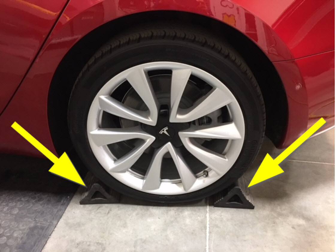
- Move the vehicle to a 2 post lift. See 举升车辆 - 双柱举升机.
-
Chock a front wheel to prevent the
vehicle from rolling in subsequent steps.
- Connect a laptop with Toolbox 3 to the vehicle. See Toolbox 3(连接和断开).
- In Toolbox 3, click the Actions tab, type "EPB" in the search field, click Start EPBL Service Mode, click Run, and allow the routine to complete.
- Hold down the brake pedal, click Start EPBR Service Mode, click Run, and allow the routine to complete.
- Click the Actions tab, type "Thermal" in the search field, click Start Thermal Fluid Fill/Drain (Coolant only), click Run, and allow the routine to complete.
- Disconnect the laptop with Toolbox 3 from the vehicle. See Toolbox 3(连接和断开).
- Remove the rear underhood apron. See 前备箱挡板 - 后部(拆卸和更换).
- Remove the cabin intake duct. See 槽 - 驾驶室进气(拆卸和更换).
- Disconnect LV power. See 12V/低压电源(断开和连接).
- 执行车辆高压禁用程序。请参阅车辆高压禁用程序。
- Remove the LH and RH rear wheels. See 轮毂(拆卸和更换).
- Remove the LH and RH rear suspension covers. See 盖板 - 后悬架 - LH(拆卸和更换).
- Remove the mid aero shield panel. See 面板 - 流线型护板 - 中间(拆卸和更换).
- Remove the rear diffuser. See 扩散器 - 后饰板(拆卸和更换).
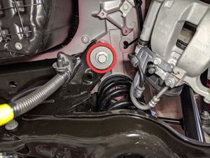
-
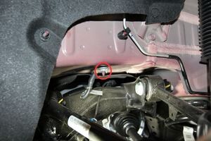
Remove the nut that attaches the rear
drive unit ground strap to the body in the LH rear wheel arch, and then remove the
ground strap from the body.
-
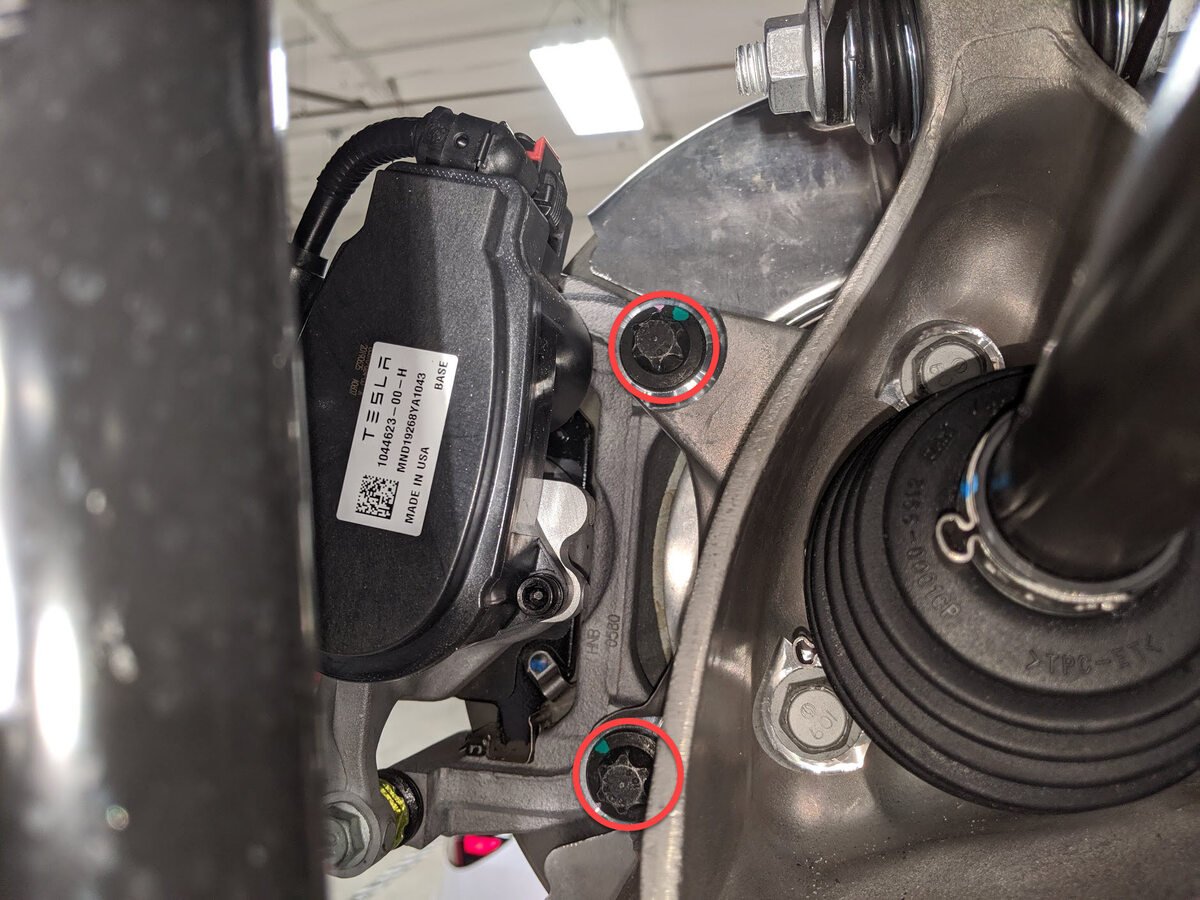
Remove and discard the bolts (x2) that
attach the LH rear brake caliper to the LH rear knuckle, remove the caliper from the
knuckle, and then hang the caliper from an S-hook.
-
Install the Gedore spring compressor
onto the LH rear coil spring, and slightly compress the spring to take the load off of
the suspension.
注Refer to the Tooling Profile for additional information.
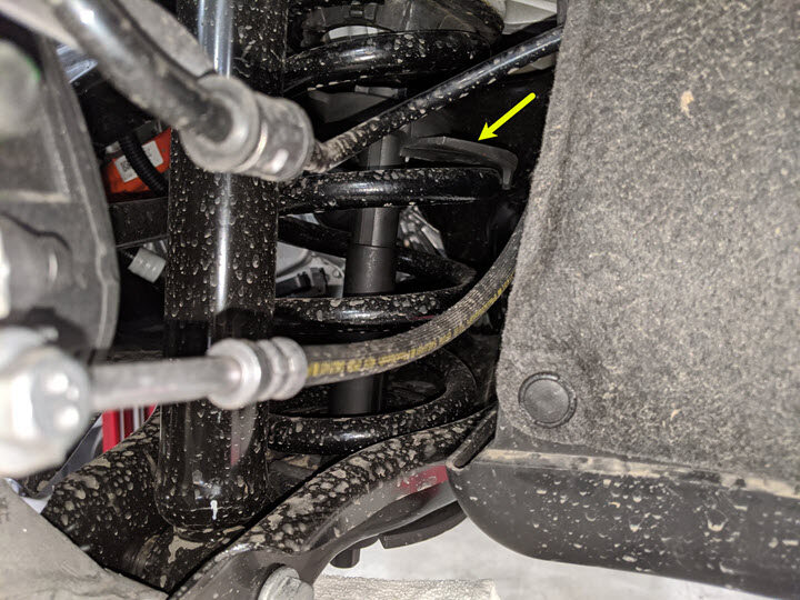
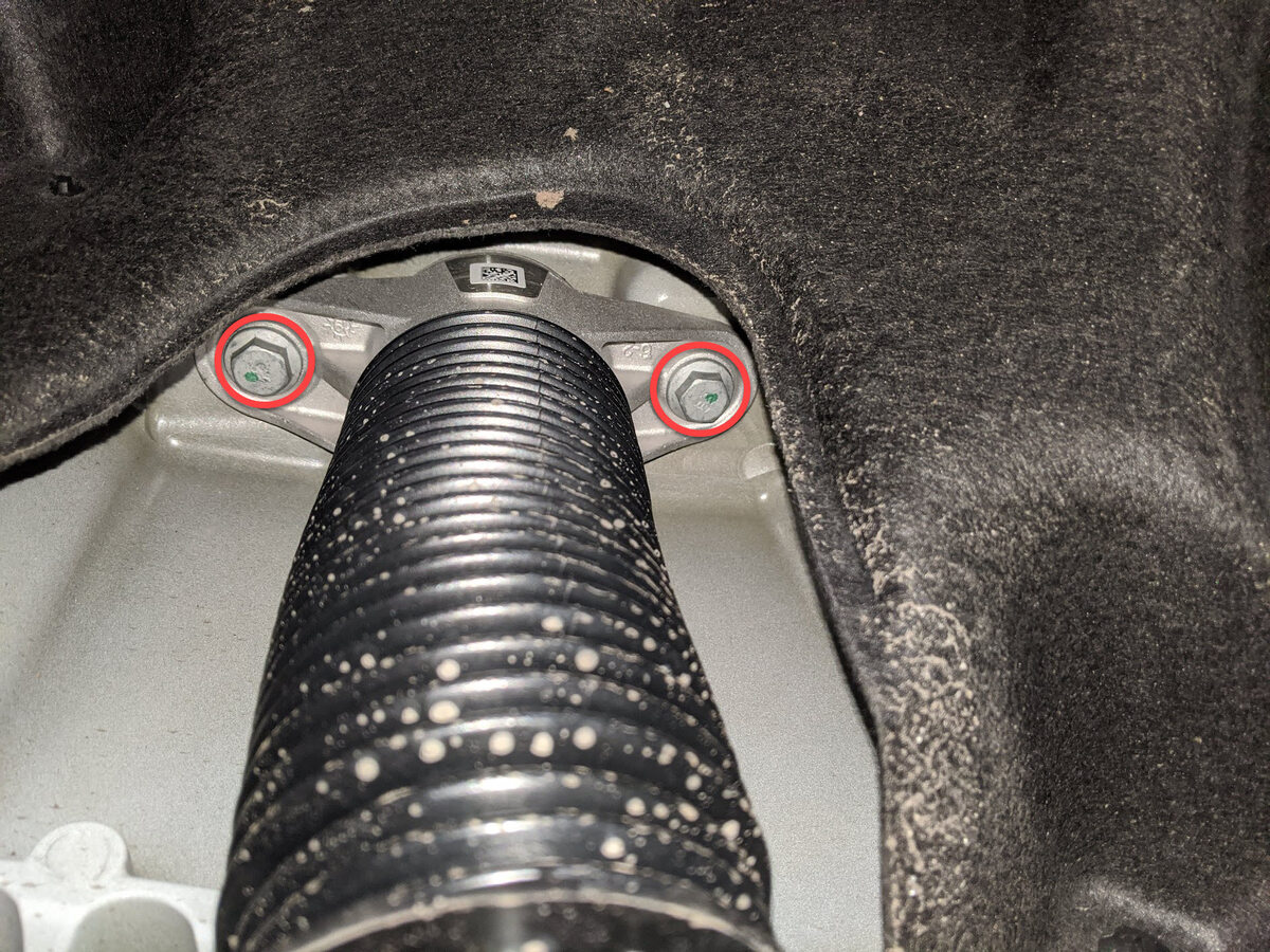
-
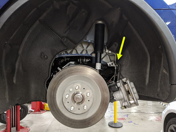
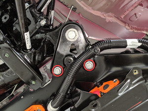
Remove the bolts (x2) that attach the
LH rear strut to the body at the LH top mount.
- Repeat step 17 through step 19 on the RH side of the vehicle.
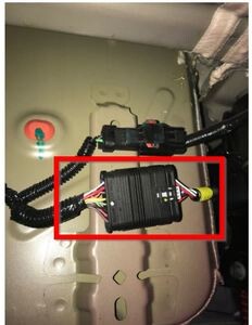
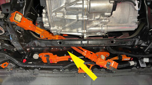
-
Disconnect the electrical harness from the rear subframe harness RH
connector.
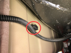
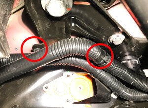
-
Release the clip that attaches the
rear subframe harness to the body on the RH side.
-
Disconnect the electrical harness from the rear subframe harness LH
connector.
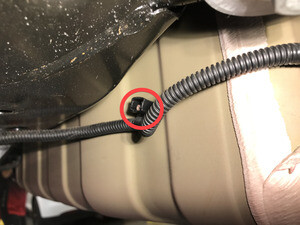
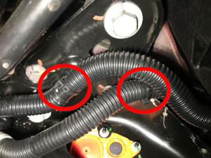
-
Release the clip that attaches the
rear subframe harness to the body on the LH side.
-
Remove and discard the nut that
attaches the LH rear stabilizer bar end link to the rear stabilizer bar.
注Use a 5mm allen wrench to prevent the ball joint stud from turning and damaging the ball joint.
-
Remove LH rear stabilizer bar end link
from the rear stabilizer bar.
注Move the stabilizer bar up and down to ease removal of the end link.
-
Remove and discard the nut that
attaches the RH rear stabilizer bar end link to the rear stabilizer bar.
注Use a 5mm allen wrench to prevent the ball joint stud from turning and damaging the ball joint.
-
Remove RH rear stabilizer bar end link
from the rear stabilizer bar.
注Move the stabilizer bar up and down to ease removal of the end link.
-
Remove and discard the bolts (x4) that
attach the rear stabilizer bar to the rear subframe, and then remove the stabilizer bar
from the subframe.
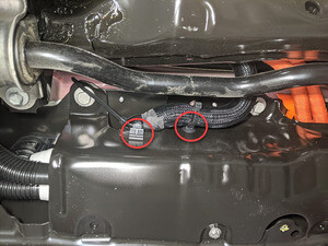
-
Release the clips (x2) that attach the
coolant hoses to LH shear plate.
-
Release the clips (x4) that attach the
coolant hoses to the rear skid plate.
注Clip quantity varies with older vehicles.
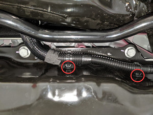
-
Release the clips (x2) that attach the
coolant hoses to RH shear plate.
- Remove the HV battery rear skid plate. See 滑板 - 高压电池 - 后部(拆卸和更换).
-
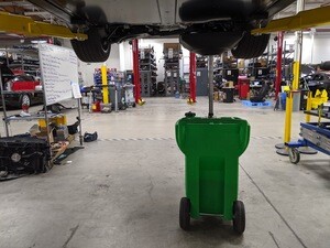
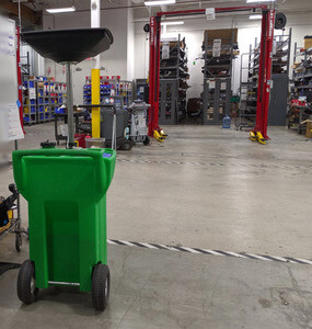
Position a coolant drain collector
underneath the LH rear of the HV battery.
-
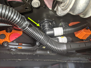
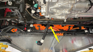
Release the clip, disconnect the rear
drive unit inverter inlet hose from the HV battery, and then immediately plug both
fittings.
-
Release the clip, disconnect the rear
drive unit inverter inlet hose from the rear drive unit inverter, and then immediately
plug both fittings.
-
Release the clip that attaches the
rear drive unit inverter inlet hose from rear drive unit HV harness.
-
Remove the rear drive unit inverter
inlet hose down and out from between the rear subframe and the HV battery.
-
Position a coolant drain collector
underneath the RH rear of the HV battery.

-
Release the clips (x2) that attach the
RH rear wheel arch liner to the RH rocker panel, and then move the liner aside for
access.
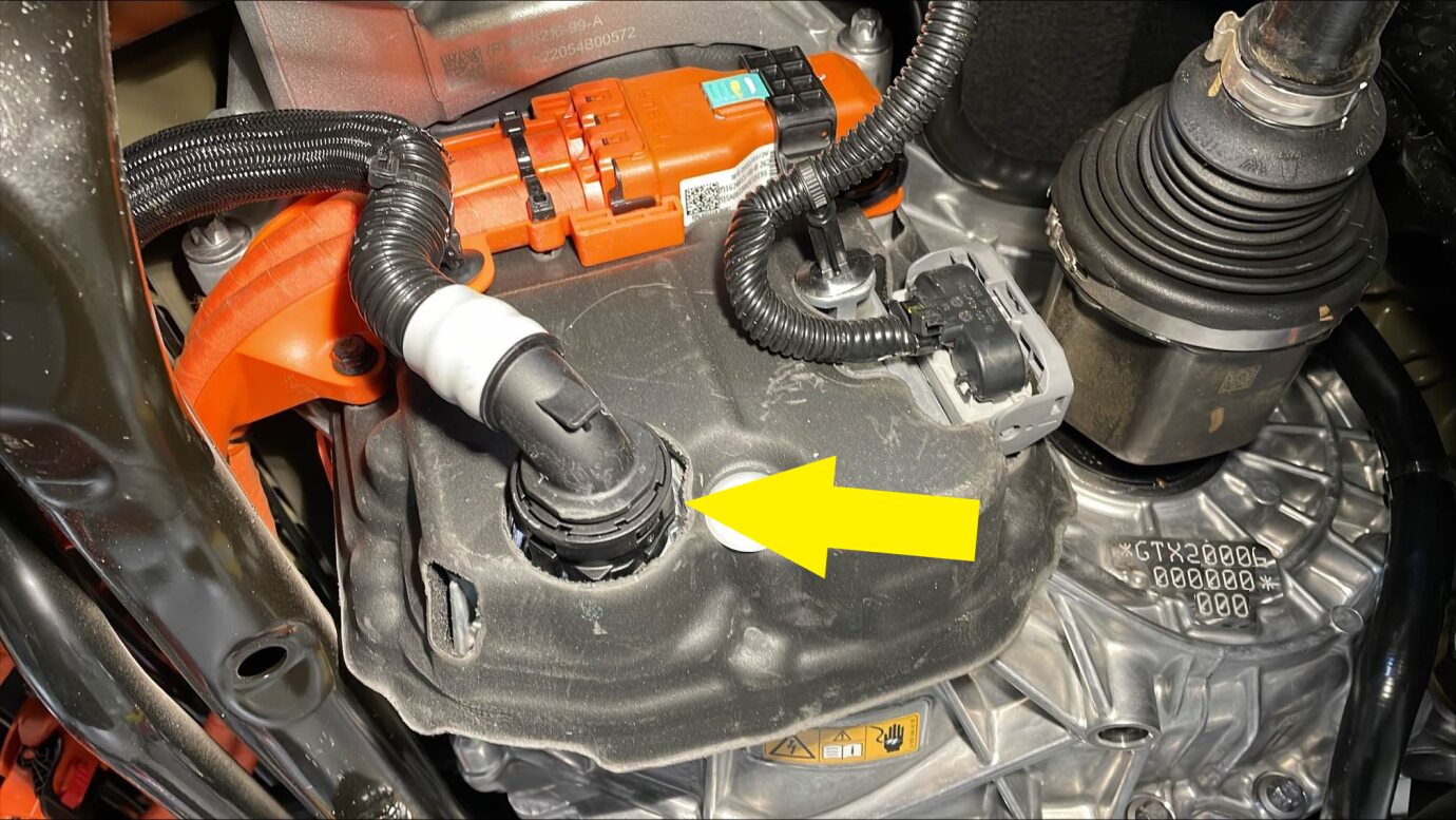
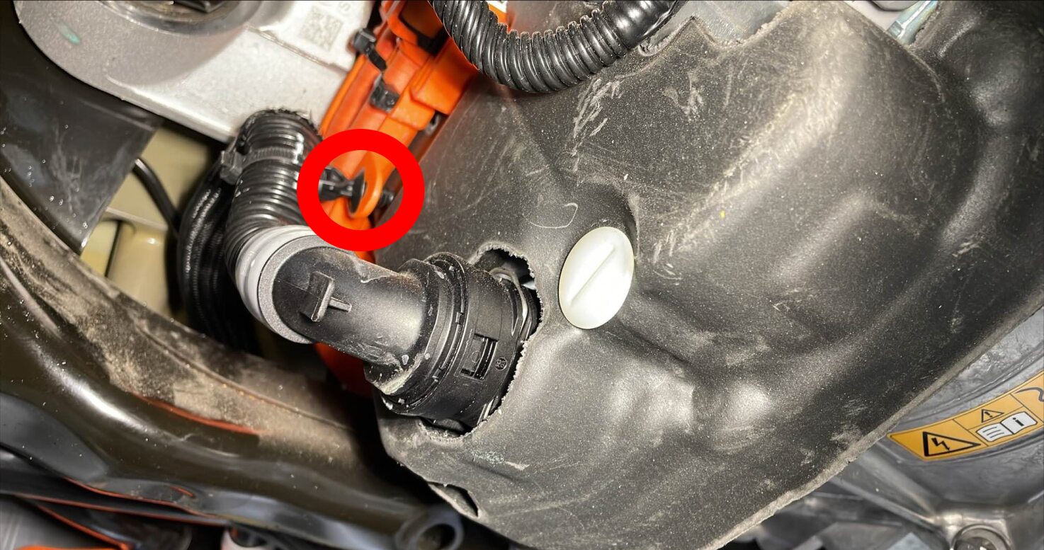
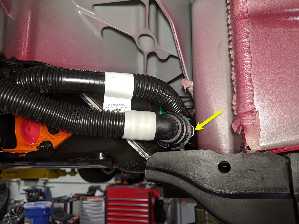
-
Release the clip, disconnect the rear
drive unit coolant outlet hose from the powertrain return hose, and then immediately
plug both fittings.
-
Remove the coolant drain collector
from under the vehicle.
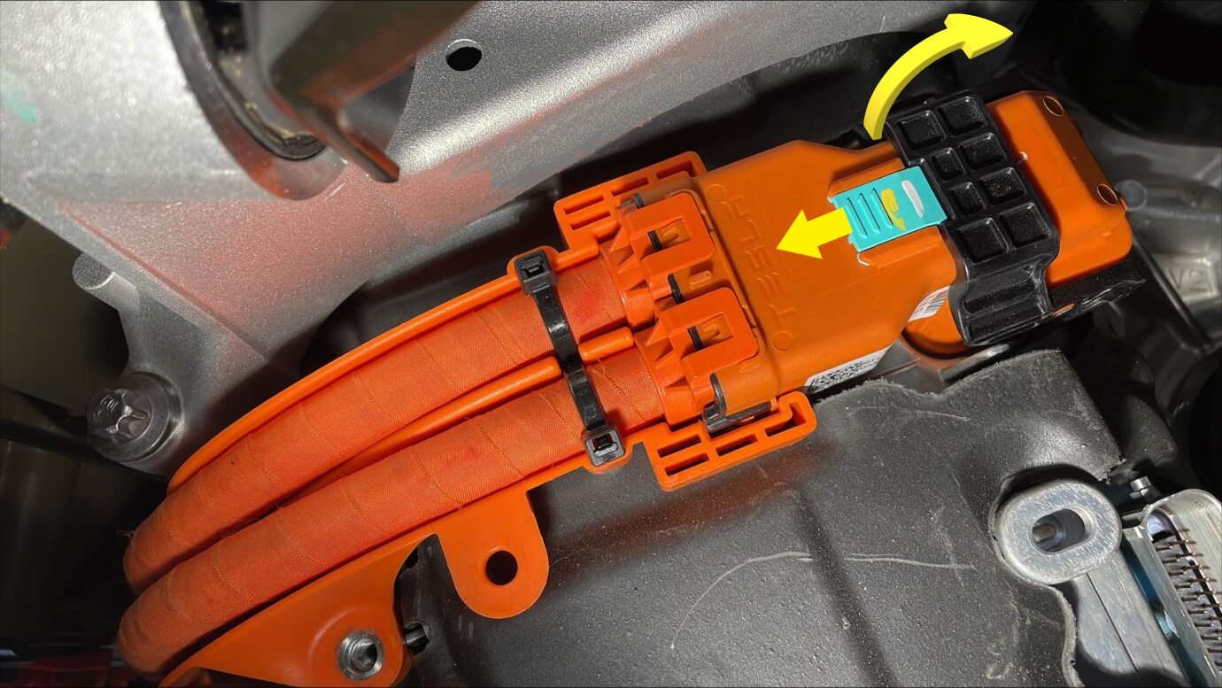
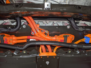
-
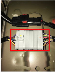
Release the locking tab, push the
handle downward, and then disconnect the rear subframe electrical harness from the rear
drive unit inverter logic connector.
警告Once disconnected, make sure that coolant does not get into the connectors.
-
Release the clip that attaches the
rear subframe electrical harness to the rear drive unit inverter.
-
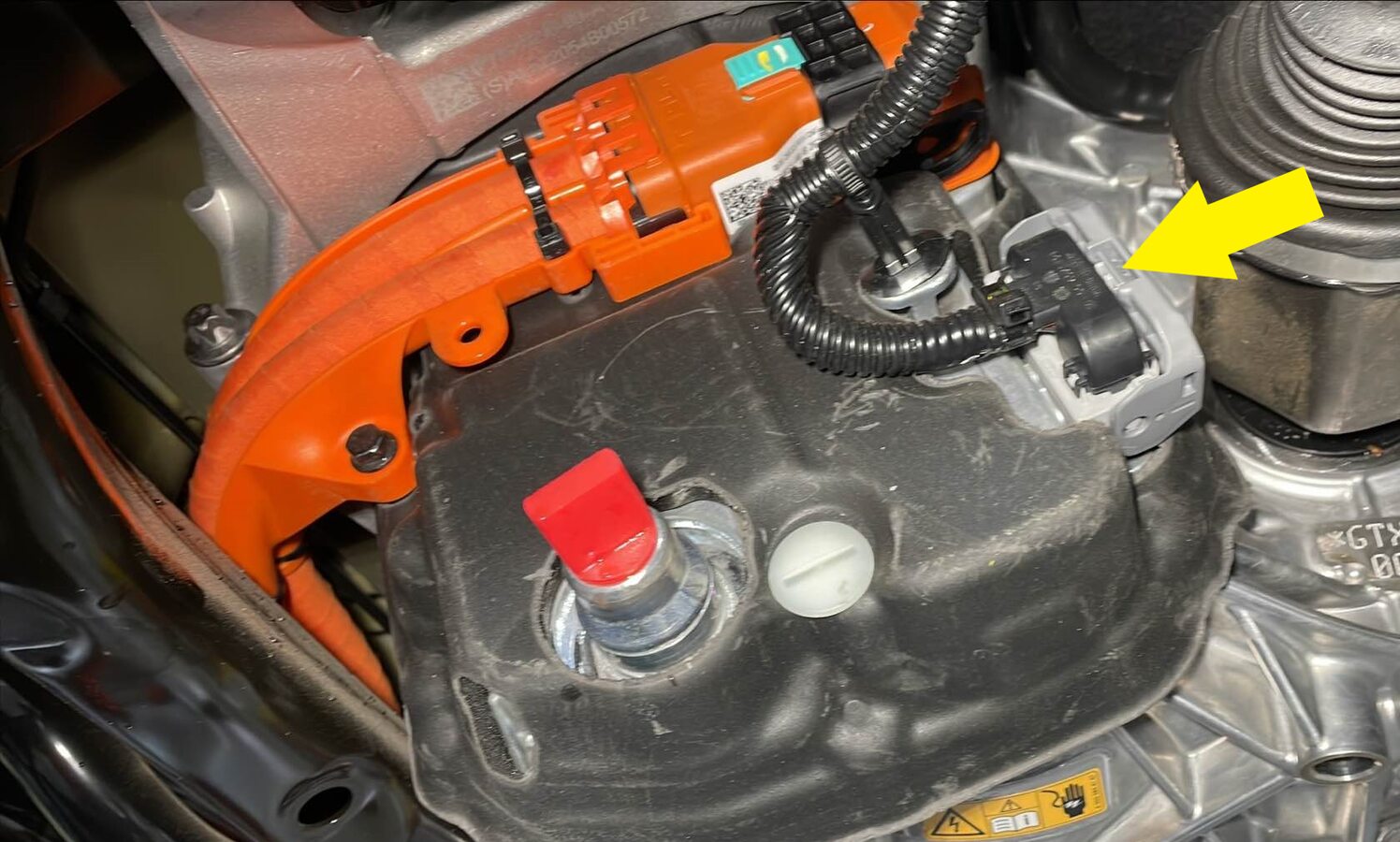
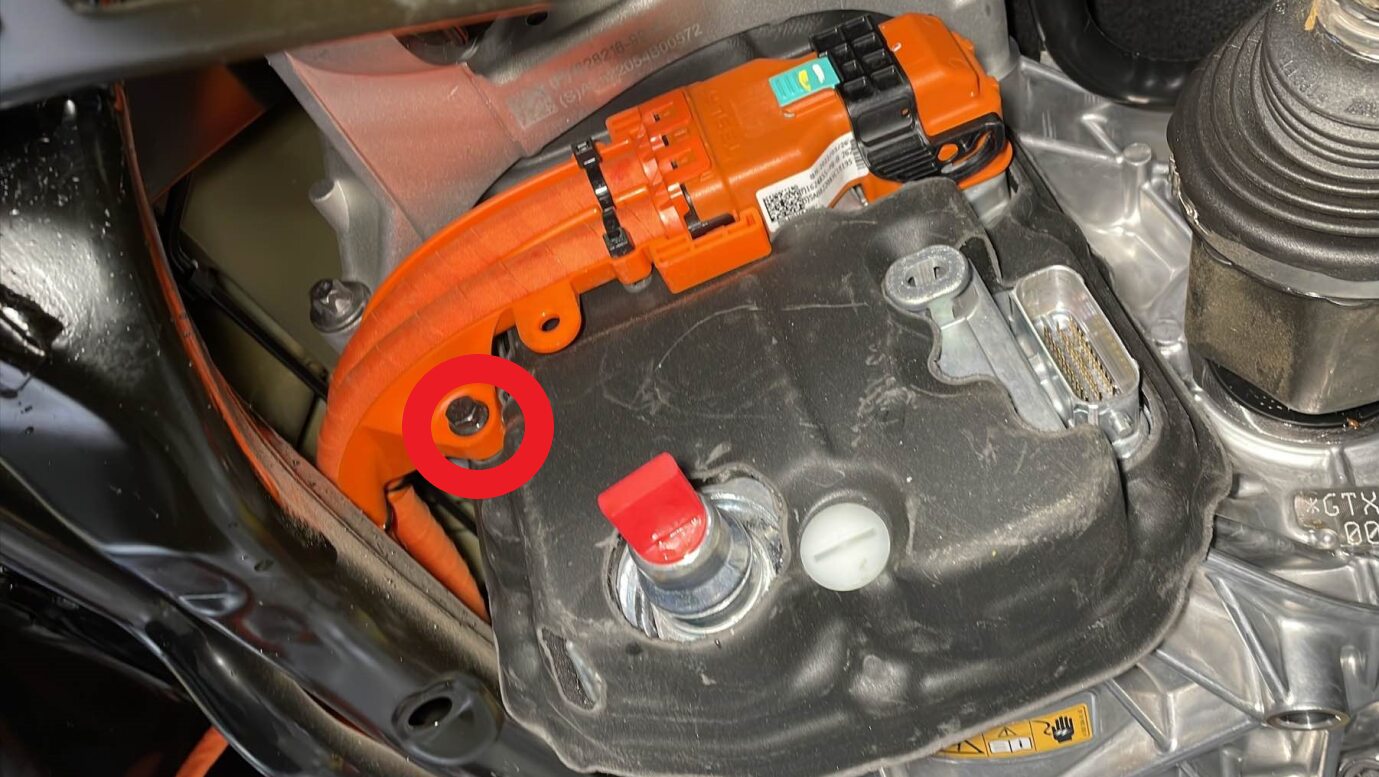
Remove the bolt that attaches the rear
drive unit HV harness bracket to the rear drive unit inverter.
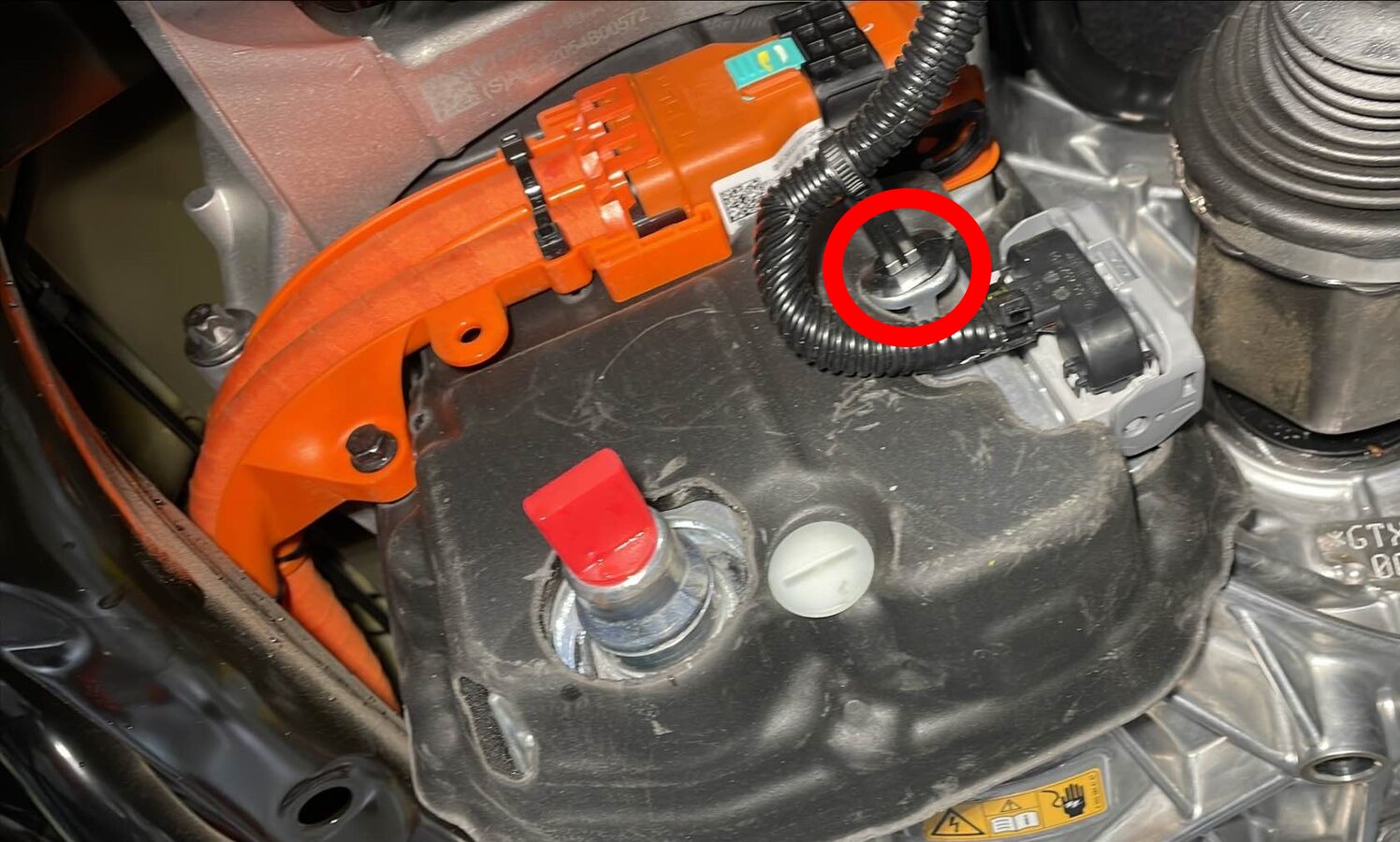
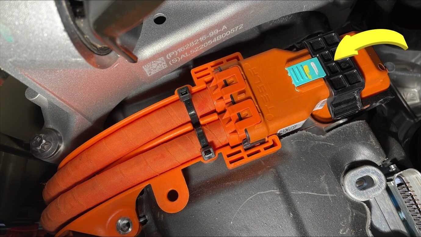
-
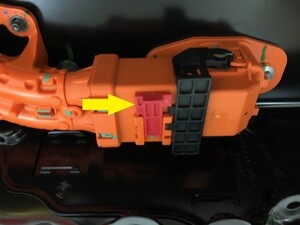
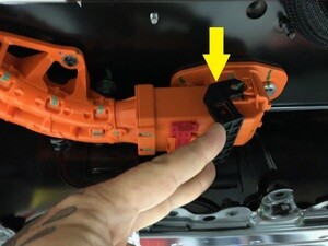
Slide the locking tab, raise the black
handle, disconnect the rear drive unit HV harness from the rear drive unit inverter HV
header,and then set the HV harness aside.
-
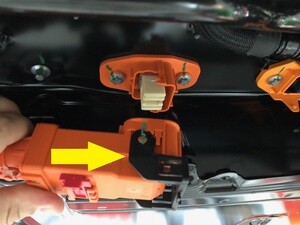
Remove the nut(s) that attach(es) the
rear drive unit HV harness bracket to the HV battery.
-
Slide the red locking tab, raise the
black handle, and then disconnect the rear drive unit HV harness from the HV battery
header.
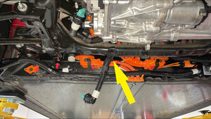
-
Remove the rear drive unit HV harness
down and out from between the rear subframe and the HV battery.
注Rotate the harness as it is removed to allow access for the bracket.

-
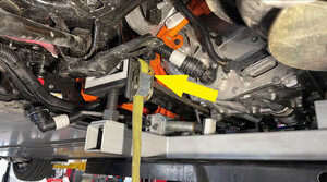
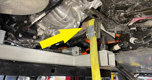
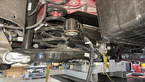
Position the subframe lifting tool
under, and up against the rear subframe.

-
With the help of an assistant, fully
secure the straps (x3) that attach the rear subframe to the subframe lifting tool.

-
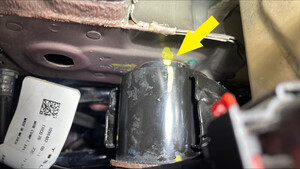
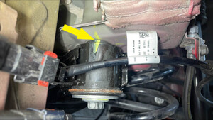
Use a paint pen to trace around the LH
and RH rear subframe mounting bolts, so that the bolts can be realigned later during the
subframe installation.
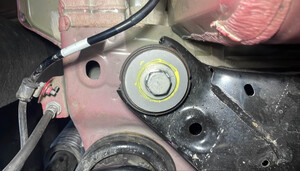
-
Use a paint pen to apply a witness
mark where the rear subframe contacts the body at the LH and RH rear subframe mounting
bolts, so that the subframe can be realigned to the body later during subframe
installation.
-
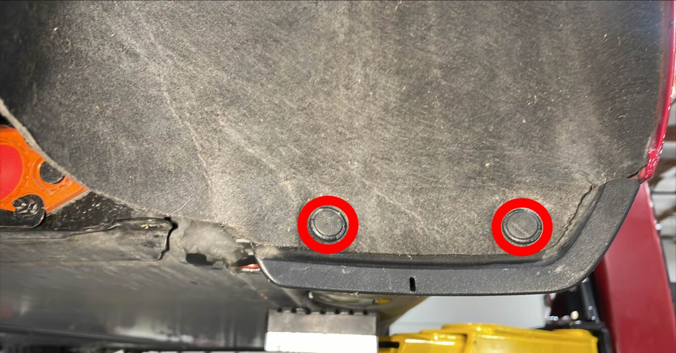
Remove the small bolts (x2) that
attach the LH shear plate to the HV battery.
-
Remove the large bolt that attaches
the LH shear plate and rear subframe to the body, and then remove shear
plate.
-
Remove the small bolts (x2) that
attach the RH shear plate to the HV battery.
-
Remove the large bolt that attaches
the RH shear plate and rear subframe to the body, and then remove shear
plate.

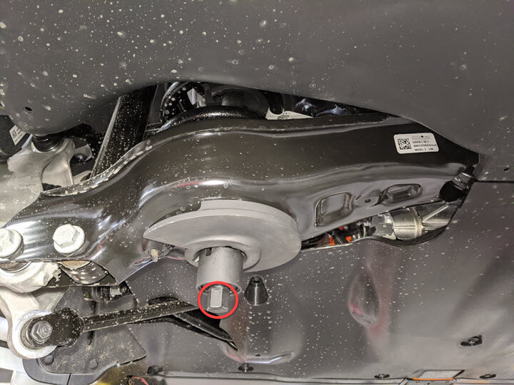
-
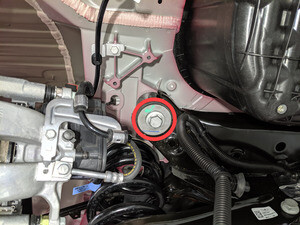
Remove and discard the LH rear
subframe bolt that attaches the subframe to the body.
-
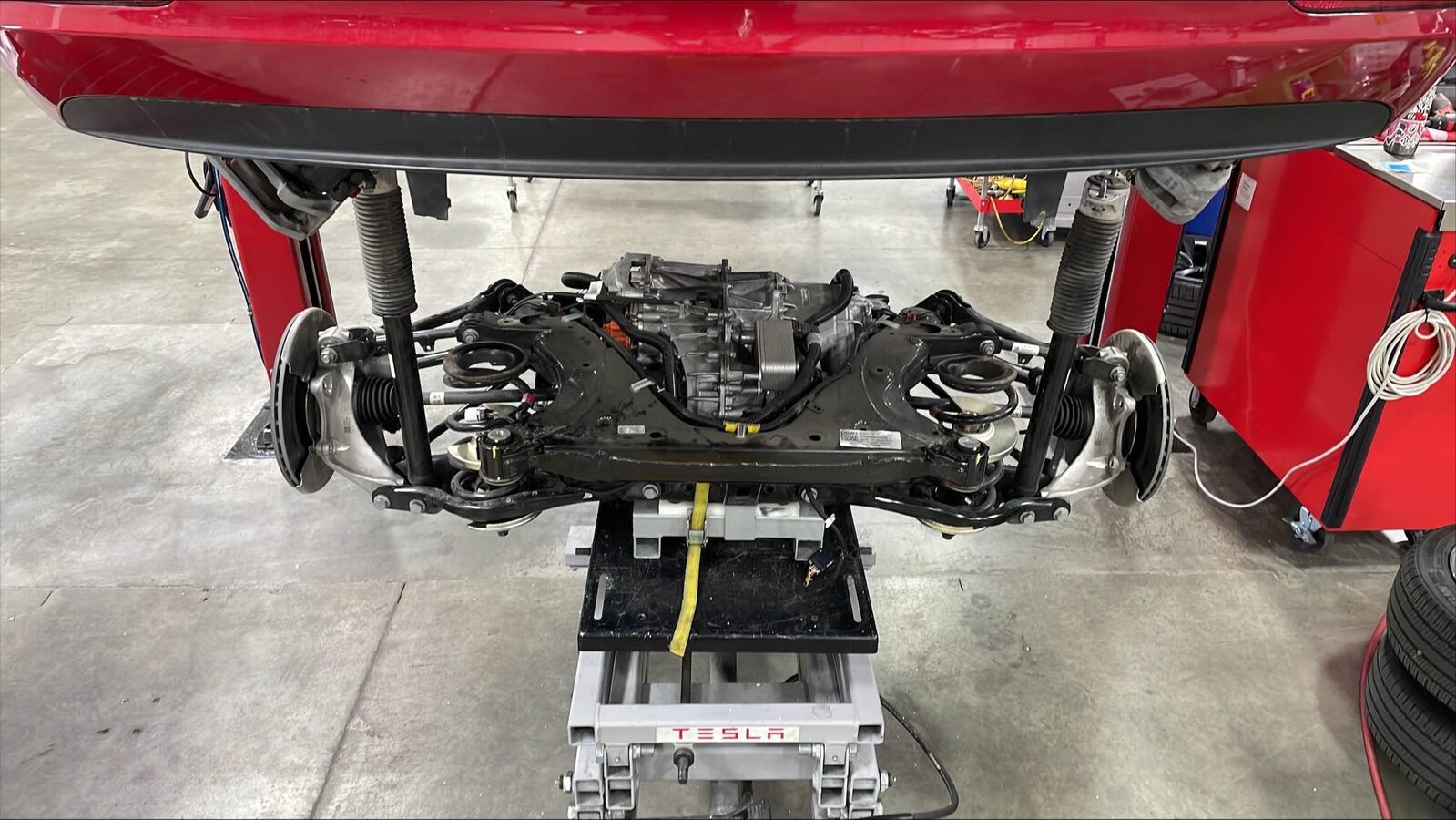
Carefully lower the rear subframe and
rear drive unit assembly from the vehicle, and move it out from under the vehicle.
警告Do not damage hoses or harnesses while lowering the subframe.
安装
-
Position the rear subframe and rear
drive unit assembly under the vehicle.
-
Carefully raise the subframe and rear
drive unit assembly until they are up against the body.
警告Do not damage hoses or harnesses while raising the subframe.
-
Install and hand-tighten a new RH rear
subframe bolt to attach the rear subframe to the body.
-
Install and hand-tighten a new LH rear
subframe bolt to attach the rear subframe to the body.
-
Install the RH shear plate to the rear
subframe, and then install a new large bolt to attach the RH shear plate and rear
subframe to the body.
-
Install and hand-tighten the small
bolts (x2) that attach the RH shear plate to the HV battery.
-
Install the LH shear plate to the rear
subframe, and then install a new large bolt to attach the LH shear plate and rear
subframe to the body.
-
Install and hand-tighten the small
bolts (x2) that attach the LH shear plate to the HV battery.
-
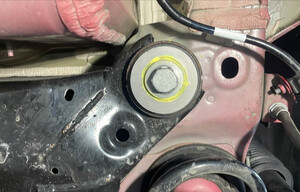
Use a pry bar to shimmy the rear
subframe with respect to the body, so that the subframe mounting bolts are centered in
the tracings, and the witness marks align where the subframe contacts the body.
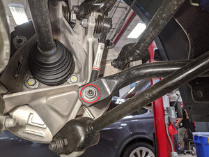
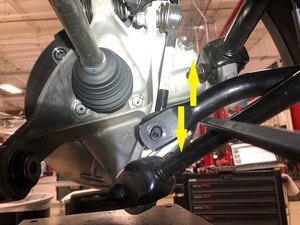
-
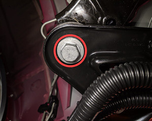
Tighten the RH rear subframe bolt that
attaches the rear subframe to the body, and then mark the bolt after
tightenting.
 165 Nm (121.7 lbs-ft)
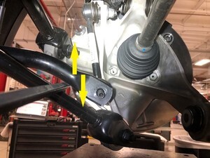
-
Tighten the LH rear subframe bolt that
attaches the rear subframe to the body, and then mark the bolt after
tightenting.165 Nm (121.7 lbs-ft)
-
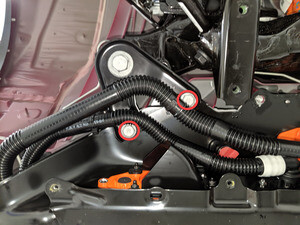
Tighten large bolt that attaches the
LH shear plate and rear subframe to the body, and then mark the bolt after
tightenting.130 Nm (95.9 lbs-ft)
-
Tighten large bolt that attaches the
RH shear plate and rear subframe to the body, and then mark the bolt after
tightenting.130 Nm (95.9 lbs-ft)
-
Tighten the small bolts (x2) that
attach the LH and RH shear plate to the HV battery.
图 1. LH side shown, RH side similar
TIp推荐使用以下工具:- 13 毫米套筒
- 3 英寸加长件
-
Release the straps (x3) that attach
the rear subframe to the subframe lifting tool.
-
Lower the subframe lifting tool, and
move it out from under the vehicle.
-
Install the rear drive unit HV harness
in and up between the rear subframe and the HV battery.
注Rotate the harness as it is installed to allow access for the bracket.
-
Verify that the black release lever of
the rear drive unit HV harness connector is in the open position, install the connector
flat and square to the HV battery header, secure the release lever to the closed
position, and then slide the red connector locking tab.
-
Install the nut(s) that attach(es) the
rear drive unit HV harness bracket to the HV battery.10 Nm (7.4 lbs-ft)
-
Verify that the black release lever of
the rear drive unit HV harness connector is in the open position, install the connector
flat and square to the rear drive unit inverter HV header, secure the release lever to
the closed position, and then slide the connector locking tab.
-
Install the bolt that attaches the
rear drive unit HV harness bracket to the rear drive unit inverter.6 Nm (4.4 lbs-ft)
- Inspect the rear subframe electrical harness logic connector and the rear drive unit inverter logic connector for coolant, and use shop air and a clean dry shop towel to remove any coolant from the connectors.
-
Connect the rear subframe electrical
harness to the rear drive unit inverter logic connector, raise the handle upward, and
fasten the locking tab.
-
Fasten the clip that attaches the rear
subframe electrical harness to the rear drive unit inverter.
-
Position a coolant drain collector
underneath the LH rear of the HV battery.
-
Install the rear drive unit inverter
inlet hose in and up between the rear subframe and the HV battery.
-
Fasten the clip that attaches the rear
drive unit inverter inlet hose to rear drive unit HV harness.
-
Remove the plugs from the fittings,
immediately connect the rear drive unit inverter inlet hose to the rear drive unit
inverter, fasten the clip, and then perform a Push-Pull-Push check of the fitting.
-
Remove the plugs from the fittings,
immediately connect the rear drive unit inverter inlet hose to the HV battery, fasten
the clip, and then perform a Push-Pull-Push check of the fitting.
-
Position the coolant drain collector
underneath the RH rear of the HV battery.
-
Remove the plugs from the fittings,
immediately connect the rear drive unit coolant outlet hose to the powertrain return
hose, fasten the clip, and then perform a Push-Pull-Push check of the fitting.
-
Return the RH rear wheel arch liner to
position, and then fasten the clips (x2) that attach the liner to the RH rocker
panel.
-
Remove the coolant drain collector
from under the vehicle.
- Install the HV battery rear skid plate. See 滑板 - 高压电池 - 后部(拆卸和更换).
-
Fasten the clips (x2) that attach the
coolant hoses to RH shear plate.
-
Fasten the clips (x4) that attach the
coolant hoses to the rear skid plate.
注Clip quantity varies with older vehicles.
-
Fasten the clips (x2) that attach the
coolant hoses to LH shear plate.
-
Install the rear stabilizer bar to the
rear subframe, and then install new bolts (x4) to attach the stabilizer bar to the
subframe.30 Nm (22.1 lbs-ft)
-
Install the LH rear stabilizer bar end
link into the rear stabilizer bar.
注Move the stabilizer bar up and down to ease installation of the end link.
-
Install a new nut to attach the LH
rear stabilizer bar end link to the rear stabilizer bar.55 Nm (40.6 lbs-ft)注Use a 5mm allen wrench to prevent the ball joint stud from turning and damaging the ball joint.
-
Install the RH rear stabilizer bar end
link into the rear stabilizer bar.
注Move the stabilizer bar up and down to ease installation of the end link.
-
Install a new nut to attach the RH
rear stabilizer bar end link to the rear stabilizer bar.55 Nm (40.6 lbs-ft)注Use a 5mm allen wrench to prevent the ball joint stud from turning and damaging the ball joint.
-
Fasten the clip that attaches the rear
subframe harness to the body on the LH side.
-
Connect electrical harness to the rear
subframe harness LH connector.
-
Fasten the clip that attaches the rear
subframe harness to the body on the RH side.
-
Connect electrical harness to the rear
subframe harness RH connector.
-
Install the rear drive unit ground
strap to the body in the LH rear wheel arch, and then install the nut that attaches the
ground strap to the body.10 Nm (7.4 lbs-ft)
-
Install the LH rear strut to the body
at the LH top mount, and then install the bolts (x2) that attach the strut to the
body.41 Nm (30.2 lbs-ft)
-
Remove the S-Hook, install the LH rear
brake caliper to the LH rear knuckle, and then install new bolts (x2) to attach the
caliper to the knuckle.83 Nm (61.2 lbs-ft)
-
Remove the Gedore spring compressor
from the LH rear coil spring.
注Refer to the Tooling Profile for additional information.
- Repeat step 48 through step 50 for the RH side of the vehicle.
- Install the rear diffuser. See 扩散器 - 后饰板(拆卸和更换).
- Install the mid aero shield panel. See 面板 - 流线型护板 - 中间(拆卸和更换).
- Install the LH and RH rear suspension covers. See 盖板 - 后悬架 - LH(拆卸和更换).
- Install the LH and RH rear wheels. See 轮毂(拆卸和更换).
- Perform a cooling system vacuum refill. See 冷却系统(真空重新加注).
- Connect LV power. See 12V/低压电源(断开和连接).
-
On the touchscreen, press and hold the
Park button to disable EPB service mode, and then remove any wheel chocks.
- Connect the laptop with Toolbox 3 to the vehicle. See Toolbox 3(连接和断开).
- In Toolbox 3, click the Actions tab, type "Thermal" in the search field, click Stop Thermal Fluid Fill/Drain, click Run, and allow the routine to complete.
- Click the Actions tab, type "Coolant" in the search field, click Coolant Air Purge, click Run, and allow the routine to complete.
- Click the Actions tab, type "Thermal" in the search field, click Thermal System Performance Test, click Run, and allow the routine to complete.
- Disconnect the laptop with Toolbox 3 from the vehicle. See Toolbox 3(连接和断开).
-
Add coolant to the reservoir as
necessary, and install the reservoir cap.
- Install the cabin intake duct. See 槽 - 驾驶室进气(拆卸和更换).
- Install the rear underhood apron. See 前备箱挡板 - 后部(拆卸和更换).
- Remove the vehicle from the 2 post lift. See 举升车辆 - 双柱举升机.
- 请参阅“定位要求”表,确定是否需要进行电动助力转向 (EPAS) 定位检查 (EC) 或四轮定位检查 (AC)。如果已执行,请作为一项单独的工项添加定位检查/调整。请参阅定位要求 - 悬架。