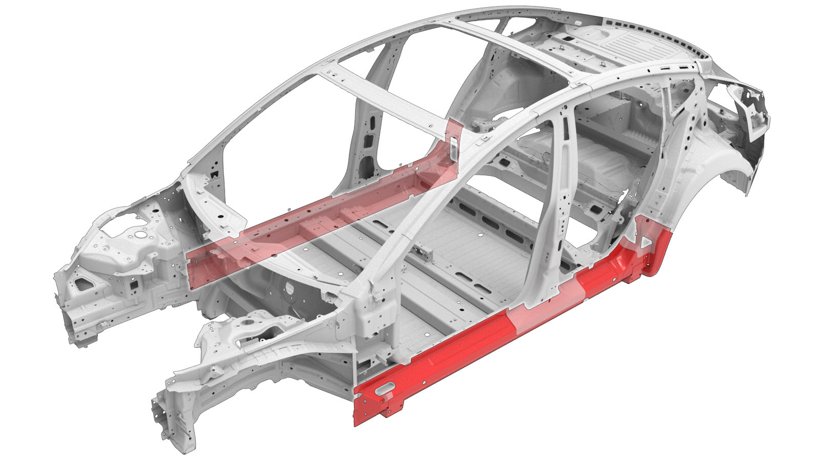
Sill Outer (Complete)
 Correction code:
10102900402
10102900702
NOTE:
Unless explicitly stated in the procedure, the above
correction code includes all Collision Repair and Service
repair work required to perform this procedure, including
the linked Collision Repair procedures and linked Service
procedures. Do not stack Collision Repair correction
codes unless explicitly told to do so. Depending
on the damage to the vehicle, additional repairs may be
required.
Correction code:
10102900402
10102900702
NOTE:
Unless explicitly stated in the procedure, the above
correction code includes all Collision Repair and Service
repair work required to perform this procedure, including
the linked Collision Repair procedures and linked Service
procedures. Do not stack Collision Repair correction
codes unless explicitly told to do so. Depending
on the damage to the vehicle, additional repairs may be
required.
Repair Information
- Review all collision repair general practices and safety documentation and wear the appropriate PPE (Personal Protective Equipment) before beginning this procedure.
- This procedure can be completed without using a frame bench.
Parts List
| Quantity | Description | Image / Notes |
|---|---|---|
| 1 | ASSY - Sill Outer (Sill Outer Assembly) | |
| 1 | Sill Insert | |
| 2 | Sill Insert Mounting Bracket | |
| 18 | High Strength Structural Rivet, 6.5 mm | |
| 6 | Structural Bulb Rivet, 6.5 mm | |
| 4 | Rivet, 4.8 mm | |
| 1 | Flow Form Rivet S08 | |
| 1 | Flow Form Rivet S18 | |
| 3 | Flow Form Rivet S38 |
When ordering parts, refer to the Parts Catalog and enter the VIN of the vehicle being repaired to find the correct parts (and the part numbers) for the vehicle. Alternatively, use the search function in the Parts Catalog to find a specific part for the vehicle.
Repair Procedure
- Remove the Sill Plate - Front - LH (Remove and Replace).
- Remove the Steering Column (LHD) (Remove and Replace).
- Remove the Cover - Rocker Panel - Lower - LH (Remove and Replace).
- Remove the Fender Assembly - Front - LH (Remove and Install).
- Remove the Door - Rear - LH (Remove and Install).
- Remove the Seal - Body - Side - Rear - Primary - LH (Remove and Replace).
- Remove the Door - Front - LH (Remove and Install).
- Remove the Seal - Body - Side - Front - Primary - LH (Remove and Replace).
- Remove the Module - Body Controller - RH (Remove and Replace).
- Remove the Module - Body Controller - LH (LHD)(Non-Heat Pump) (Remove and Replace).
- Remove the Beam - Cross Car (LHD) (Remove and Replace).
- Remove the IP Carrier (Remove and Install).
- Remove the Windshield (Reuse Humidity and Temperature Sensor) (Remove and Replace).
- Remove the Carpet - Interior Complete (Remove and Replace).
- Remove the Trim - A-Pillar - Upper - LH (Remove and Replace).
- Remove the Bolster - Side - Seat - 2nd Row - LH (Remove and Replace).
- Remove the Trim - Sill Panel - Rear - LH (Remove and Replace).
- Remove the Trim - B-Pillar - Lower - LH (Remove and Replace).
- Remove the HV Battery (RWD) (Remove and Install).
- Remove the Wheel Arch Liner - Front - LH (Remove and Replace).
- Remove the Cover - Rocker Panel - Lower - LH (Remove and Replace).
- Remove the Wheel Arch Liner - Rear - LH (Remove and Replace).
- Remove the Brake Lines - LH Sill (Remove and Replace).
- Remove the Brake Fluid Bleed - One Caliper.
-
Remove the necessary portion of the Body Side Outer Assembly to expose the underlying component being replaced.
-
Remove the Hinge Pillar (Section).
-
Remove the lower section of
the C–Pillar Reinforcement.
-
Remove the original component.
Cut Line
or Factory SPRs
or Factory Structural Rivets
or Factory Spot Welds
or Drill through factory spot weldsNoteWhen drilling out spot welds, use a drill bit that creates a hole correctly sized for the fastener that will replace the spot weld. -
Remove the Sill
Insert.
-
From the back side of the Sill Outer, separate the spot welds at the bottom
flange of the B–Pillar Outer (the area circled in red).
or Factory Spot WeldsNoteDo not drill through or damage the bottom flange of the B–Pillar Outer.
-
Mark the center line for the
installation for the Sill Insert Mounting Brackets on the new Sill Insert as
shown below.
- A = 260 mm
- B = 221 mm
NoteThe measurements are from the end of the Sill Insert to the center of the Sill Insert Mounting Bracket. -
Clamp the new Sill Insert to
the new Sill Outer in the locations indicated.
- C = 173 mm
- D = 51 mm
- Position the Sill Insert Mounting Brackets between the Sill Insert and the Sill Outer along the center line drawn in an earlier step, and adjust the brackets so that they make contact with the Sill Outer.
-
Prepare to install the Sill Insert Mounting Brackets.
- Apply structural adhesive to the mating surfaces of the Sill Insert Mounting Brackets and the Sill Insert.
- Install the Sill Insert Mounting Brackets on the Sill Insert.
-
Prepare to install the new Sill Insert in the new Sill
Outer.
- Apply structural adhesive to the mating surfaces on Sill Insert Mounting Brackets, the Sill Insert, and the Sill Outer.
- Install the Sill Insert in the new Sill Outer Assembly.
-
Prepare to install the new Sill Outer Assembly
NoteA red X indicates a location where a factory-installed fastener is not being replaced. Secure this location using structural adhesive only.
or Installation Spot Welds
or High Strength Structural Rivets, 6.5 mmNoteThe upper row of rivets securing the bottom of the B–Pillar should match the factory spot weld locations.- E = 15 mm
NoteThe center of all rivets in the bottom row of structural rivets must be at the indicated height from the lower edge of the new component, as shown below.or Rivets, 4.8 mm- F = 10 mm
- G = 74 mm
or Structural Bulb Rivets, 6.5 mm
GMA Weld
- Apply structural adhesive to the mating surfaces on the vehicle and the new component or components.
- Install the new component or components.
-
Perform resistance spot
welding.
or Installation Spot WeldsWarningFailure to follow all welding safety precautions, including the use of personal protective equipment, could result in serious injury or property damage. Only technicians who have completed Tesla’s approved welding training are authorized to weld structural components on Tesla vehicles.CAUTIONDo not weld on a Tesla vehicle before performing the Vehicle Electrical Isolation Procedure (refer to the vehicle-specific Service Manual for more information on the Vehicle Electrical Isolation Procedure). Welding on a Tesla vehicle with an energized high or low voltage system might damage vehicle components.
-
Perform GMA welding.
GMA Weld
WarningFailure to follow all welding safety precautions, including the use of personal protective equipment, could result in serious injury or property damage. Only technicians who have completed Tesla’s approved welding training are authorized to weld structural components on Tesla vehicles.WarningTo maintain vehicle crash integrity, use only approved welding wire and an approved GMA welder to perform GMA welding on Tesla vehicles. Refer to Approved Gas Metal Arc (GMA) Welders and Welding Wire for information on approved GMA welders and welding wire.CAUTIONDo not weld on a Tesla vehicle before performing the Vehicle Electrical Isolation Procedure (refer to the vehicle-specific Service Manual for more information on the Vehicle Electrical Isolation Procedure). Welding on a Tesla vehicle with an energized high or low voltage system might damage vehicle components.NoteBefore GMA welding, a test weld using material of the same gauge and type should be performed to make sure that the welding equipment settings produce a satisfactory joint. -
Install the lower section of
the C–Pillar Reinforcement.
-
Install the Hinge Pillar (Section).
-
Install the portion of the
Body Side Outer Assembly that was removed to expose the
component being replaced.
-
Install the fasteners as indicated.
- Perform any necessary post-repair operations.
- Install the Brake Fluid Bleed - One Caliper.
- Install the Brake Lines - LH Sill (Remove and Replace).
- Install the Wheel Arch Liner - Rear - LH (Remove and Replace).
- Install the Cover - Rocker Panel - Lower - LH (Remove and Replace).
- Install the Wheel Arch Liner - Front - LH (Remove and Replace).
- Install the HV Battery (RWD) (Remove and Install).
- Install the Trim - B-Pillar - Lower - LH (Remove and Replace).
- Install the Trim - Sill Panel - Rear - LH (Remove and Replace).
- Install the Bolster - Side - Seat - 2nd Row - LH (Remove and Replace).
- Install the Trim - A-Pillar - Upper - LH (Remove and Replace).
- Install the Carpet - Interior Complete (Remove and Replace).
- Install the Windshield (Reuse Humidity and Temperature Sensor) (Remove and Replace).
- Install the IP Carrier (Remove and Install).
- Install the Beam - Cross Car (LHD) (Remove and Replace).
- Install the Module - Body Controller - LH (LHD)(Non-Heat Pump) (Remove and Replace).
- Install the Module - Body Controller - RH (Remove and Replace).
- Install the Seal - Body - Side - Front - Primary - LH (Remove and Replace).
- Install the Door - Front - LH (Remove and Install).
- Install the Seal - Body - Side - Rear - Primary - LH (Remove and Replace).
- Install the Door - Rear - LH (Remove and Install).
- Install the Fender Assembly - Front - LH (Remove and Install).
- Install the Cover - Rocker Panel - Lower - LH (Remove and Replace).
- Install the Steering Column (LHD) (Remove and Replace).
- Install the Sill Plate - Front - LH (Remove and Replace).