Quarter Outer Skin
 Correction code:
10100122302
10100118102
NOTE:
Unless explicitly stated in the procedure, the above
correction code includes all Collision Repair and Service
repair work required to perform this procedure, including
the linked Collision Repair procedures and linked Service
procedures. Do not stack Collision Repair correction
codes unless explicitly told to do so. Depending
on the damage to the vehicle, additional repairs may be
required.
Correction code:
10100122302
10100118102
NOTE:
Unless explicitly stated in the procedure, the above
correction code includes all Collision Repair and Service
repair work required to perform this procedure, including
the linked Collision Repair procedures and linked Service
procedures. Do not stack Collision Repair correction
codes unless explicitly told to do so. Depending
on the damage to the vehicle, additional repairs may be
required.
Repair Information
- The lower section of the Quarter Outer Skin can be replaced so long as the referenced cut line from the Quarter Outer Skin Section Descriptions portion of this document are used.
- Review all collision repair general practices and safety documentation and wear the appropriate PPE (Personal Protective Equipment) before beginning this procedure.
- This procedure can be completed without using a frame bench.
Parts List
| Quantity | Description | Image / Notes |
|---|---|---|
| 1 | PANEL - REAR QUARTER OUTER (Quarter Outer Skin) | |
| 11 | Flow Form Rivet S18 |
When ordering parts, refer to the Parts Catalog and enter the VIN of the vehicle being repaired to find the correct parts (and the part numbers) for the vehicle. Alternatively, use the search function in the Parts Catalog to find a specific part for the vehicle.
Quarter Outer Skin Section Descriptions
- If a section repair requires the removal or installation of additional panels or assemblies, perform the necessary procedures using the specific repair procedure for each panel or assembly.
- It is allowable to cut through a clearance hole or a non functional hole (exterior trim hole), as described below.
- Do not cut within 25 mm. of the center of a bolt hole.
- Sections do not require fasteners at butt joints unless specifically indicated.
- A backing plate may be installed at a butt joint between sections (as described in create and install backing plates).
- Gaps between panels of butt joints should be as small as possible to maximize joint strength.
- GMA weld section butt joints.
- Seal all open seams after welding.
- If a butt joint includes a flange, do not weld on the flange (flanges are secured using only structural adhesive).
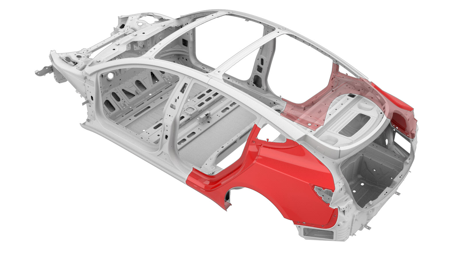
The images below show the Quarter Outer Skin. The colored areas indicate if sectioning is allowed. Compare the damaged area of the vehicle's Quarter Outer Skin to the images below, then use the repair criteria corresponding to the color of the highlighted area to find the criteria to use to determine if the damaged area of the component can be sectioned.
| Quarter Outer Skin Sectioning | |
|---|---|
|
Warning If sectioning
in this area, use caution when welding due to the underlying aluminum
panel. |
|
|
Note If sectioning in this area, do
not weld the butt joint in the indicated area; instead, fill the seam with
structural adhesive. |
Based on the colors used in the image above, the allowed repairs are as follows:
| Area Color | Area Repairability |
|---|---|
| Green areas: | Sectioning is allowed in these areas. |
| Yellow areas: | Sectioning is allowed in these areas. Foam is located behind
the panel. Note If sectioning in
this area, remove the foam and then clean the area to avoid weld
contamination. |
| Red areas: | Sectioning is not allowed. |
Repair Procedure
- Remove the Door Assembly - Charge Port (NA) (Harness Type) (Remove and Replace).
- Remove the Glass - Body - Rear Quarter - LH (Remove and Install).
- Remove the Seal - Secondary - Rear Door - LH (Remove and Replace).
- Remove the Wheel Arch Liner - Rear - LH (Remove and Replace).
- Remove the Trim - Side - Trunk - RH (Remove and Replace).
- Remove the Trim - Side - Trunk - LH (Remove and Replace).
- Remove the Air Extractor - LH (Remove and Replace).
- Remove the Trim - C-Pillar - Rear - LH (Remove and Replace).
- Remove the Seat Back - 2nd Row - RH (Remove and Replace).
- Remove the Seat Back - 2nd Row - LH (Remove and Replace).
- Remove the Bracket - Taillight - LH (Remove and Replace).
- Remove the Bracket - Rear Wing - LH (Remove and Replace).
- Remove the Cover - Rocker Panel - Lower - LH (Remove and Replace).
- Remove the Seal - Body - Side - Rear - Primary - LH (Remove and Replace).
- Remove the Reflex Lens - Rear - RH (Remove and Replace).
- Remove the Trim - Sill Panel - Rear - LH (Remove and Replace).
- Remove the Striker - Door - Rear - LH (Remove and Replace).
-
Remove the original component.
or Factory SPRs
or Factory Spot Welds
-
Separate the rear wheel arch
flange.
-
Prepare for installation.
NoteA red X indicates a location where a factory-installed fastener is not being replaced. Secure this location using structural adhesive only.
or Steel Plug Welds
-
Apply seam sealer in the area where the Charge Port Housing Bracket makes direct contact to the Quarter Panel skin and the factory foam baffle (shown here in orange).
CAUTIONThis procedure calls for a seam sealer with a cured elongation rating of greater than 150%. This is to prevent visible distortion of the quarter panel’s exterior surface where the Charge Port Housing Bracket is bonded to the inside of the panel.CAUTIONIf using a seam sealer not designed for application over bare metal surfaces, the mating surface on the inside of the quarter panel will require refinishing prior to installing the Charge Port Housing Assembly. Refer to the technical data sheet for the seam sealing product being used.
- Apply structural adhesive to the mating surfaces on the vehicle and the new component or components.
-
Install the new component or components.
NoteThe Body Side Outer lower flange is secured using structural adhesive only.
-
Fold over the wheel arch flange.
-
Perform GMA welding.
or Steel Plug Welds
GMA Weld
WarningDo not weld the panel where it directly contacts the high strength panels underneath. The heat from welding might weaken the strength of the underlying high strength steel structure.WarningFailure to follow all welding safety precautions, including the use of personal protective equipment, could result in serious injury or property damage. Only technicians who have completed Tesla’s approved welding training are authorized to weld structural components on Tesla vehicles.WarningTo maintain vehicle crash integrity, use only approved welding wire and an approved GMA welder to perform GMA welding on Tesla vehicles. Refer to Approved Gas Metal Arc (GMA) Welders and Welding Wire for information on approved GMA welders and welding wire.WarningBefore GMA welding, make sure that the structural adhesive is dry to the touch. If the structural adhesive is not dry to the touch before GMA welding, the strength of the adhesive bond might be compromised.CAUTIONDo not weld on a Tesla vehicle before performing the Vehicle Electrical Isolation Procedure (refer to the vehicle-specific Service Manual for more information on the Vehicle Electrical Isolation Procedure). Welding on a Tesla vehicle with an energized high or low voltage system might damage vehicle components.NoteBefore GMA welding, a test weld using material of the same gauge and type should be performed to make sure that the welding equipment settings produce a satisfactory joint. - For vehicles in China only: Install a new Manufacturing Certificate Label (refer to the Model 3 Service Manual procedure for more information).
- Perform any necessary post-repair operations.
- Install the Striker - Door - Rear - LH (Remove and Replace).
- Install the Trim - Sill Panel - Rear - LH (Remove and Replace).
- Install the Reflex Lens - Rear - RH (Remove and Replace).
- Install the Seal - Body - Side - Rear - Primary - LH (Remove and Replace).
- Install the Cover - Rocker Panel - Lower - LH (Remove and Replace).
- Install the Bracket - Rear Wing - LH (Remove and Replace).
- Install the Bracket - Taillight - LH (Remove and Replace).
- Install the Seat Back - 2nd Row - LH (Remove and Replace).
- Install the Seat Back - 2nd Row - RH (Remove and Replace).
- Install the Trim - C-Pillar - Rear - LH (Remove and Replace).
- Install the Air Extractor - LH (Remove and Replace).
- Install the Trim - Side - Trunk - LH (Remove and Replace).
- Install the Trim - Side - Trunk - RH (Remove and Replace).
- Install the Wheel Arch Liner - Rear - LH (Remove and Replace).
- Install the Seal - Secondary - Rear Door - LH (Remove and Replace).
- Install the Glass - Body - Rear Quarter - LH (Remove and Install).
- Install the Door Assembly - Charge Port (NA) (Harness Type) (Remove and Replace).