Rear Wheel Arch (Complete)
 Correction code:
10101909202
10101909102
NOTE:
Unless explicitly stated in the procedure, the above
correction code includes all Collision Repair and Service
repair work required to perform this procedure, including
the linked Collision Repair procedures and linked Service
procedures. Do not stack Collision Repair correction
codes unless explicitly told to do so. Depending
on the damage to the vehicle, additional repairs may be
required.
Correction code:
10101909202
10101909102
NOTE:
Unless explicitly stated in the procedure, the above
correction code includes all Collision Repair and Service
repair work required to perform this procedure, including
the linked Collision Repair procedures and linked Service
procedures. Do not stack Collision Repair correction
codes unless explicitly told to do so. Depending
on the damage to the vehicle, additional repairs may be
required.
Repair Information
- Review all collision repair general practices and safety documentation and wear the appropriate PPE (Personal Protective Equipment) before beginning this procedure.
- This procedure can be completed without using a frame bench.
- The Rear Wheel Arch Assembly can be:
- Replaced in a single repair as a single complete component, using the service part and the instructions in the Repair Procedure section of this document.
- Repaired in sections that are larger or smaller than the service part. Any individual section or any combination of sections of the Rear Wheel Arch can be replaced so long as the guidelines from the Sectioning Guidelines are followed.
Parts List
| Quantity | Description | Image / Notes |
|---|---|---|
| 1 | M3 ASY, RR W/H OUTER COMPLETE (Rear Wheel Arch) | |
| 13 | Rivet, 4.8 mm | |
| 4 | Structural Bulb Rivet, 6.5 mm | |
| 6 | Countersunk Rivet, 4.8 mm Long | |
| 1 | Flow Form Rivet S18 |
When ordering parts, refer to the Parts Catalog and enter the VIN of the vehicle being repaired to find the correct parts (and the part numbers) for the vehicle. Alternatively, use the search function in the Parts Catalog to find a specific part for the vehicle.
Sectioning Guidelines
- It is allowable to cut through a clearance hole or a non functional hole (exterior trim hole), as described below.
- Do not cut within 25 mm of the center of a stud.
- Seal all open seams after structural adhesive has cured.
- Seal all open seams after welding.
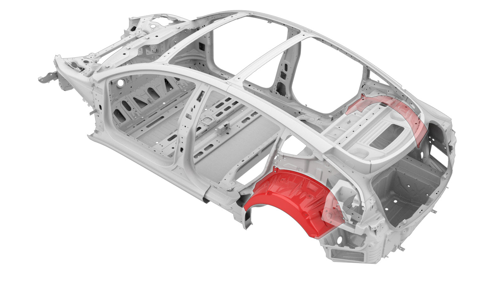
| Rear Wheel Arch Sectioning |
|---|
|
|
Based on the colors used in the image above, the allowed repairs are as follows:
| Area Color | Area Repairability |
|---|---|
| Green areas: | Sectioning is allowed in these areas. Overlap
joints must have an overlap of at least a 25 mm, which must be secured with
structural adhesive. Note When using an overlap joint between a red area and a
green area, the red area must overlap the green area by at least 25 mm. Do not
overlap from a green area into a red area. Note The gap between
the adjacent panels of the butt joint for this section should be as small as
possible to maximize joint strength. |
| Yellow areas: | Sectioning is allowed in these areas. Note Sectioning in these areas
requires the component be returned to its original geometry for proper function.
Overlap joints must have an overlap of at least a 25 mm, which must be
secured with structural adhesive. Note When using an overlap joint
between a red area and a yellow area, the red area must overlap the yellow
area by at least 25 mm. Do
not overlap from a yellow area into a red area. Areas shown
in yellow may include areas that allow water ingress, so use special care to
make sure that seals fit correctly in all repaired areas. Note Once the repair is complete,
make sure that all seals fit properly and make sure that water does not
ingress in the repair area. Other components may mount to the
Rear Wheel Arch in these areas. Use special care to make sure that openings in
repair area are the same size as the original openings, and ensure that mounting
areas allow components to fit properly. Note Once the repair is complete,
make sure that mounted components are flush with the Body Side Outer surface
and that the components fit correctly in all repaired
areas. |
| Red areas: | Sectioning is not allowed. |
Repair Procedure
- RH component only: Remove the Subwoofer (Remove and Replace).
- LH component only: Remove the ECU - Charge Port (Remove and Replace).
- Remove the Wheel Arch Liner - Rear - LH (Remove and Replace).
-
Remove the necessary portion of the
Quarter Outer Skin to expose the
underlying component being replaced.
-
Detach the original Rear Wheel
Arch.
or Factory Spot Welds
or Factory SPRs
-
Remove the indicated portion of the Rear Wheel Arch.
Cut Line
-
Remove the remaining portion of the original Rear Wheel Arch.
NoteA red X indicates a location where a factory-installed fastener is not being replaced. Secure this location using structural adhesive only.
or Factory Spot Welds
or Drill through factory spot weldsNoteWhen drilling out spot welds, use a drill bit that creates a hole correctly sized for the fastener that will replace the spot weld. -
Prepare for installation.
or Rivets, 4.8 mmNoteA red X indicates a location where a factory-installed fastener is not being replaced. Secure this location using structural adhesive only.
or Countersunk Rivets, 4.8 mm Long
- Apply structural adhesive to the mating surfaces on the vehicle and the new component or components.
- Install the new component or components.
-
Install the portion of the Quarter Outer Skin that was removed to
expose the component being replaced.
- Perform any necessary post-repair operations.
- Install the Wheel Arch Liner - Rear - LH (Remove and Replace).
- LH component only: Install the ECU - Charge Port (Remove and Replace).
- RH component only: Install the Subwoofer (Remove and Replace).