Body Side Outer
 Correction code:
10100102502
10100121502
NOTE:
Unless explicitly stated in the procedure, the above
correction code includes all Collision Repair and Service
repair work required to perform this procedure, including
the linked Collision Repair procedures and linked Service
procedures. Do not stack Collision Repair correction
codes unless explicitly told to do so. Depending
on the damage to the vehicle, additional repairs may be
required.
Correction code:
10100102502
10100121502
NOTE:
Unless explicitly stated in the procedure, the above
correction code includes all Collision Repair and Service
repair work required to perform this procedure, including
the linked Collision Repair procedures and linked Service
procedures. Do not stack Collision Repair correction
codes unless explicitly told to do so. Depending
on the damage to the vehicle, additional repairs may be
required.
Repair Information
- Review all collision repair general practices and safety documentation and wear the appropriate PPE (Personal Protective Equipment) before beginning this procedure.
- This procedure can be completed without using a frame bench.
- The Body Side Outer Assembly
can be:
- Replaced in a single repair as a single complete component, using the M3 ASY, BODY SIDE OUTER service part and the instructions in the Repair Procedure section of this document.
- Repaired using any of the pre-cut service assemblies shown in Service Assemblies. If replacing a portion of the Body Side Outer (not the entire Body Side Outer Assembly) using a service assembly, use only the relevant portions of each step in the Repair Procedure to determine which parts and fasteners are needed and the steps required to complete the repair.
- Repaired in sections that are larger or smaller than the service assemblies. Any individual section or any combination of sections of the Body Side Outer Assembly can be replaced so long as the guidelines from the Sectioning Guidelines are followed.
Parts List
| Quantity | Description | Image / Notes |
|---|---|---|
| 1 | M3 ASY, BODY SIDE OUTER (Body Side Outer) |
Note A pre-cut sub assembly may be
used if sectioning the Body Side Outer. |
| 1 | PLUG,ROUND,25MM,TPV,BLK |
Tesla part number 1077461-00-A.
Note Required only if repairing the
Quarter section on vehicles built before 5-October-20. Note This part
is not required if using the ASSEMBLY - REAR QUARTER OUTER - LEFT - NON POWER
TRUNK 1073677-S0-A. |
| 10 | Structural Bulb Rivet, 6.5 mm | |
| 2 | Countersunk Rivet, 4.8 mm Short | |
| 1 | Countersunk Rivet, 4.8 mm Long | |
| 2 | Structural Countersunk Rivet, 6.5 mm | |
| 11 | Flow Form Rivet S18 | |
| 1 | Flow Form Rivet S28 | |
| 2 | Bolt , SEMS,[FL],HX,M8X23.5,[109],G1009,PTC | Tesla part number 1063260-00-C. |
| 1 | Rivnut,M6x1,4.0mm GRP,STL,ZnNi | Tesla part number 1038174-00-A. Note Required only if repairing the
Quarter section and the vehicle has a Rivnut to attach the ground wire to the
Charge Port Housing Assembly. |
Service Assemblies
| Body Side Outer Service Assemblies | ||
|---|---|---|
| ASY, A PLR BODY SIDE OTR | ASY, B PLR BODY SIDE OTR | ASY, REAR QUARTER OUTER ASSY |
Sectioning Guidelines
- If a section repair requires the removal or installation of additional panels or assemblies, perform the necessary procedures using the specific repair procedure for each panel or assembly.
- It is allowable to cut through a clearance hole or a non functional hole (exterior trim hole), as described below.
- Do not cut within 25 mm. of the center of a bolt hole.
- Sections do not require fasteners at butt joints unless specifically indicated.
- A backing plate may be installed at a butt joint between sections (as described in create and install backing plates).
- Gaps between panels of butt joints should be as small as possible to maximize joint strength.
- GMA weld section butt joints.
- Seal all open seams after welding.
- If a butt joint includes a flange, do not weld on the flange (flanges are secured using only structural adhesive).
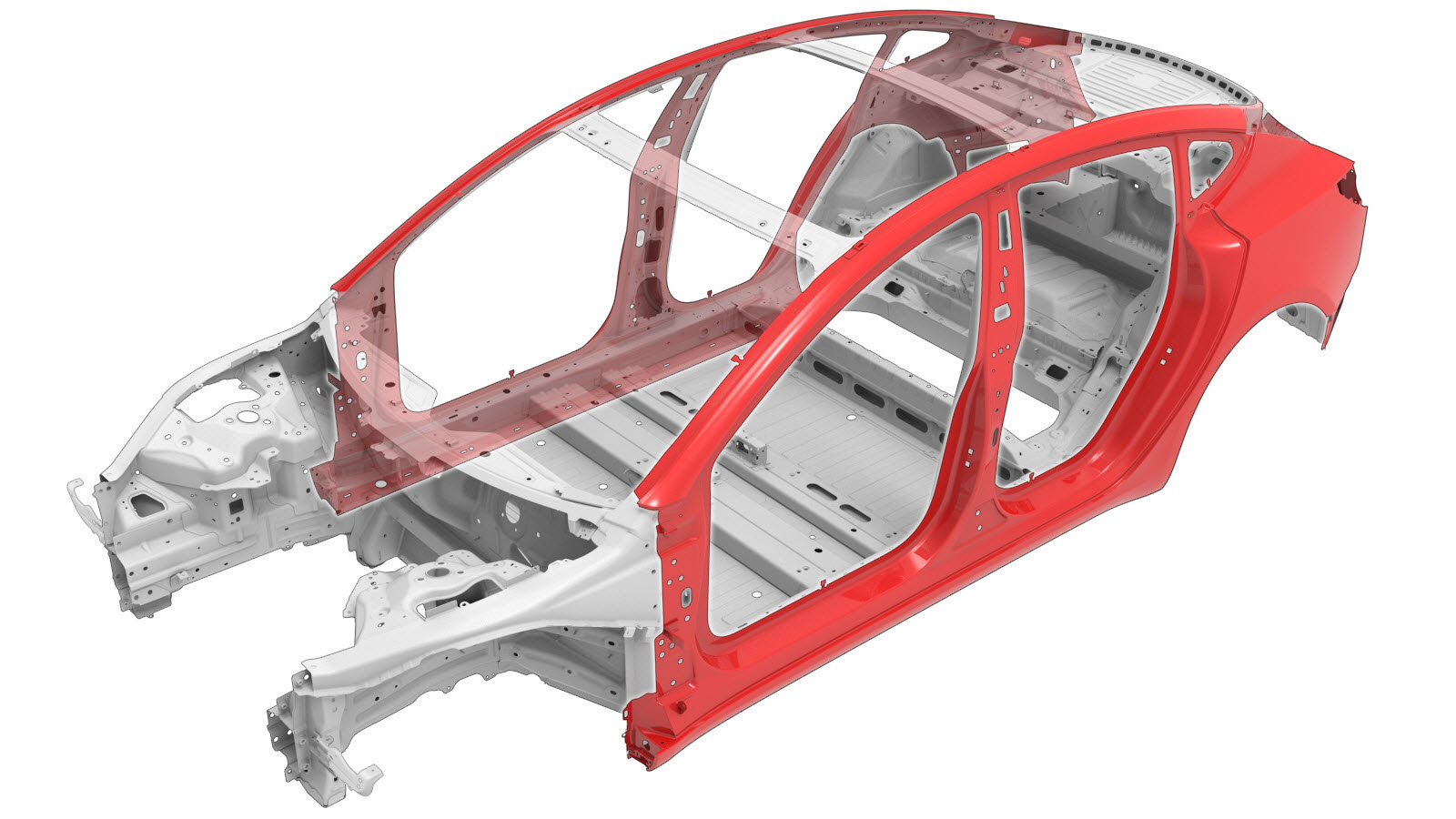
The images below show the Body Side Outer (complete). The colored areas indicate if sectioning is allowed. Compare the damaged area of the vehicle's Body Side Outer to the images below, then use the repair criteria corresponding to the color of the highlighted area to find the criteria to use to determine if the damaged area of the component can be sectioned.
| Body Side Outer Sectioning | |
|---|---|
|
Note Sectioning
of Service Assemblies is identical to the corresponding area
of the Body Side Outer (complete). |
|
|
Note If
sectioning in this area, do not weld the butt joint in the
indicated area; instead, fill the seam with strucrutal
adhesive. |
|
|
Warning If sectioning in
this area, use caution when welding due to the underlying aluminum panel. |
Based on the colors used in the image above, the allowed repairs are as follows:
| Area Color | Area Repairability |
|---|---|
| Green areas: | Sectioning is allowed in these areas. |
| Yellow areas: | Sectioning is allowed in these areas. Foam is located behind
the panel. Note If sectioning in
this area, remove the foam and then clean the area to avoid weld
contamination. |
| Red areas: | Sectioning is not allowed. |
Repair Procedure
- Remove the Cover - Rocker Panel - Lower - LH (Remove and Replace).
- Remove the Fender Assembly - Front - LH (Remove and Install).
- Remove the Windshield (Vehicles with 2nd Generation or Later Autopilot) (Remove and Replace).
- Remove the Bumper Beam - Rear (Remove and Replace).
- Remove the Bracket - Rear Wing - LH (Remove and Replace).
- Remove the Air Extractor - LH (Remove and Replace).
- Remove the Subwoofer (Remove and Replace).
- Remove the Charge Port (Busbar Type) (NACS) (Remove and Replace).
- Remove the Door Assembly - Charge Port (NA) (Harness Type) (Remove and Replace).
- Remove the Airbag - Curtain - LH (Remove and Replace).
- Remove the Glass - Roof - Fixed (Remove and Replace).
- Remove the Door - Front - LH (Remove and Install).
- Remove the Seal - Body - Side - Front - Primary - LH (Remove and Replace).
- Remove the Striker - Door - Front - LH (Remove and Replace).
- Remove the Hinge - Door - Front - Upper - LH (Remove and Replace).
- Remove the Hinge - Door - Front - Lower - LH (Remove and Replace).
- Remove the Door - Rear - LH (Remove and Install).
- Remove the Seal - Body - Side - Rear - Primary - LH (Remove and Replace).
- Remove the Striker - Door - Rear - LH (Remove and Replace).
- Remove the Hinge - Rear Door - Upper - LH (Remove & Replace).
- Remove the Hinge - Door - Rear - Lower - LH (Remove and Replace).
- Remove the Glass - Body - Rear Quarter - LH (Remove and Install).
- Remove the Brightwork - Upper - LH (Remove and Replace).
- Remove the Wheel Arch Liner - Rear - LH (Remove and Replace).
- Remove the Carpet - Rear Trunk (1-Piece) (Remove and Replace).
- Remove the Hinge - Trunk - LH (Remove and Replace).
- Remove the Hinge - Power Trunk - LH (Remove and Replace).
- Remove the Seatbelt - 2nd Row - LH (Remove and Replace).
- Remove the Trim - B-Pillar - Lower - LH (Remove and Replace).
- Remove the Trim - B-Pillar - Upper - LH (Remove and Replace).
- Remove the Reflex Lens - Rear - RH (Remove and Replace).
- Remove the Power Trunk (Remove and Install).
- Remove the Glass - Backlight (Heat Pump) (Remove and Install).
- If replacing a section of the Body Side Outer: Mark the Body Side Outer at the section cut line locations as described in the Sectioning Guidelines.
-
Remove the original component.
or Factory Spot Weldsor Drill through factory spot weldsNoteWhen drilling out spot welds, use a drill bit that creates a hole correctly sized for the fastener that will replace the spot weld.
or Factory SPRs
or Bolts
-
Separate the Wheel Arch flange.
-
Prepare for installation.
NoteIf replacing a section of the Body Side Outer (not the entire Body Side Outer Assembly), use the relevant portions of each step to determine which parts and fasteners are needed and the steps required to complete the repair.NoteA red X indicates a location where a factory-installed fastener is not being replaced.
or Countersunk Rivets, 4.8 mm Short
or Countersunk Rivets, 4.8 mm Long
or Structural Bulb Rivets, 6.5 mmNoteMake sure that the rivet circled in red connects all underlaying panels.or Structural Countersunk Rivets, 6.5 mm
or Installation Spot Welds
or Steel Plug Welds
-
If replacing the Quarter section of
the Body Side Outer of a vehicle built before 5-October-20 and the supplied part's
Upper Trough does not match the vehicle, modify the part by using the underlying
panel for reference to mark and cut 2 holes in the locations outlined in green (shown
below).
- Apply structural adhesive to the mating surfaces on the vehicle and the new component or components.
-
Install the new component or components.
Torque the bolts to 35 Nm.NoteThe Body Side Outer lower flange is secured using structural adhesive only.
-
Perform resistance spot
welding.
or Installation Spot Welds
or Steel Plug Welds
WarningFailure to follow all welding safety precautions, including the use of personal protective equipment, could result in serious injury or property damage. Only technicians who have completed Tesla’s approved welding training are authorized to weld structural components on Tesla vehicles.CAUTIONDo not weld on a Tesla vehicle before performing the Vehicle Electrical Isolation Procedure (refer to the vehicle-specific Service Manual for more information on the Vehicle Electrical Isolation Procedure). Welding on a Tesla vehicle with an energized high or low voltage system might damage vehicle components. -
If replacing a section of
the Body Side Outer,
perform GMA welding on the butt joints.
GMA WeldWarningDo not weld the panel where it directly contacts the high strength panels underneath. The heat from welding might weaken the strength of the underlying high strength steel structure.WarningFailure to follow all welding safety precautions, including the use of personal protective equipment, could result in serious injury or property damage. Only technicians who have completed Tesla’s approved welding training are authorized to weld structural components on Tesla vehicles.WarningTo maintain vehicle crash integrity, use only approved welding wire and an approved GMA welder to perform GMA welding on Tesla vehicles. Refer to Approved Gas Metal Arc (GMA) Welders and Welding Wire for information on approved GMA welders and welding wire.WarningBefore GMA welding, make sure that the structural adhesive is dry to the touch. If the structural adhesive is not dry to the touch before GMA welding, the strength of the adhesive bond might be compromised.CAUTIONDo not weld on a Tesla vehicle before performing the Vehicle Electrical Isolation Procedure (refer to the vehicle-specific Service Manual for more information on the Vehicle Electrical Isolation Procedure). Welding on a Tesla vehicle with an energized high or low voltage system might damage vehicle components.NoteBefore GMA welding, a test weld using material of the same gauge and type should be performed to make sure that the welding equipment settings produce a satisfactory joint.
-
Fold over the Wheel Arch flange.
-
If replacing the Quarter section of
the Body Side Outer of a vehicle built before 5-October-20 and the supplied part's
Upper Trough does not match the vehicle,
perform GMA welding to close the hole outlined in red.
WarningDo not weld the panel where it directly contacts the high strength panels underneath. The heat from welding might weaken the strength of the underlying high strength steel structure.WarningFailure to follow all welding safety precautions, including the use of personal protective equipment, could result in serious injury or property damage. Only technicians who have completed Tesla’s approved welding training are authorized to weld structural components on Tesla vehicles.WarningTo maintain vehicle crash integrity, use only approved welding wire and an approved GMA welder to perform GMA welding on Tesla vehicles. Refer to Approved Gas Metal Arc (GMA) Welders and Welding Wire for information on approved GMA welders and welding wire.WarningBefore GMA welding, make sure that the structural adhesive is dry to the touch. If the structural adhesive is not dry to the touch before GMA welding, the strength of the adhesive bond might be compromised.CAUTIONDo not weld on a Tesla vehicle before performing the Vehicle Electrical Isolation Procedure (refer to the vehicle-specific Service Manual for more information on the Vehicle Electrical Isolation Procedure). Welding on a Tesla vehicle with an energized high or low voltage system might damage vehicle components.NoteBefore GMA welding, a test weld using material of the same gauge and type should be performed to make sure that the welding equipment settings produce a satisfactory joint.
-
If replacing the Quarter section of
the Body Side Outer of a vehicle built before 5-October-20 and the supplied part's
Upper Trough does not match the vehicle, install the pass through plug in the
existing hole as shown.
-
If replacing the Quarter
section and the original Charge Port Housing had a ground wire or
harness attachment point, drill a hole in the new Charge Port Housing
for a Rivnut or a retainer clip.
Rivnut
Refer to the Charge Port Housing procedure for information about the size and location of the hole.
- Perform any necessary post-repair operations.
- Install the Glass - Backlight (Heat Pump) (Remove and Install).
- Install the Power Trunk (Remove and Install).
- Install the Reflex Lens - Rear - RH (Remove and Replace).
- Install the Trim - B-Pillar - Upper - LH (Remove and Replace).
- Install the Trim - B-Pillar - Lower - LH (Remove and Replace).
- Install the Seatbelt - 2nd Row - LH (Remove and Replace).
- Install the Hinge - Power Trunk - LH (Remove and Replace).
- Install the Hinge - Trunk - LH (Remove and Replace).
- Install the Carpet - Rear Trunk (1-Piece) (Remove and Replace).
- Install the Wheel Arch Liner - Rear - LH (Remove and Replace).
- Install the Brightwork - Upper - LH (Remove and Replace).
- Install the Glass - Body - Rear Quarter - LH (Remove and Install).
- Install the Hinge - Door - Rear - Lower - LH (Remove and Replace).
- Install the Hinge - Rear Door - Upper - LH (Remove & Replace).
- Install the Striker - Door - Rear - LH (Remove and Replace).
- Install the Seal - Body - Side - Rear - Primary - LH (Remove and Replace).
- Install the Door - Rear - LH (Remove and Install).
- Install the Hinge - Door - Front - Lower - LH (Remove and Replace).
- Install the Hinge - Door - Front - Upper - LH (Remove and Replace).
- Install the Striker - Door - Front - LH (Remove and Replace).
- Install the Seal - Body - Side - Front - Primary - LH (Remove and Replace).
- Install the Door - Front - LH (Remove and Install).
- Install the Glass - Roof - Fixed (Remove and Replace).
- Install the Airbag - Curtain - LH (Remove and Replace).
- Install the Door Assembly - Charge Port (NA) (Harness Type) (Remove and Replace).
- Install the Charge Port (Busbar Type) (NACS) (Remove and Replace).
- Install the Subwoofer (Remove and Replace).
- Install the Air Extractor - LH (Remove and Replace).
- Install the Bracket - Rear Wing - LH (Remove and Replace).
- Install the Bumper Beam - Rear (Remove and Replace).
- Install the Windshield (Vehicles with 2nd Generation or Later Autopilot) (Remove and Replace).
- Install the Fender Assembly - Front - LH (Remove and Install).
- Install the Cover - Rocker Panel - Lower - LH (Remove and Replace).