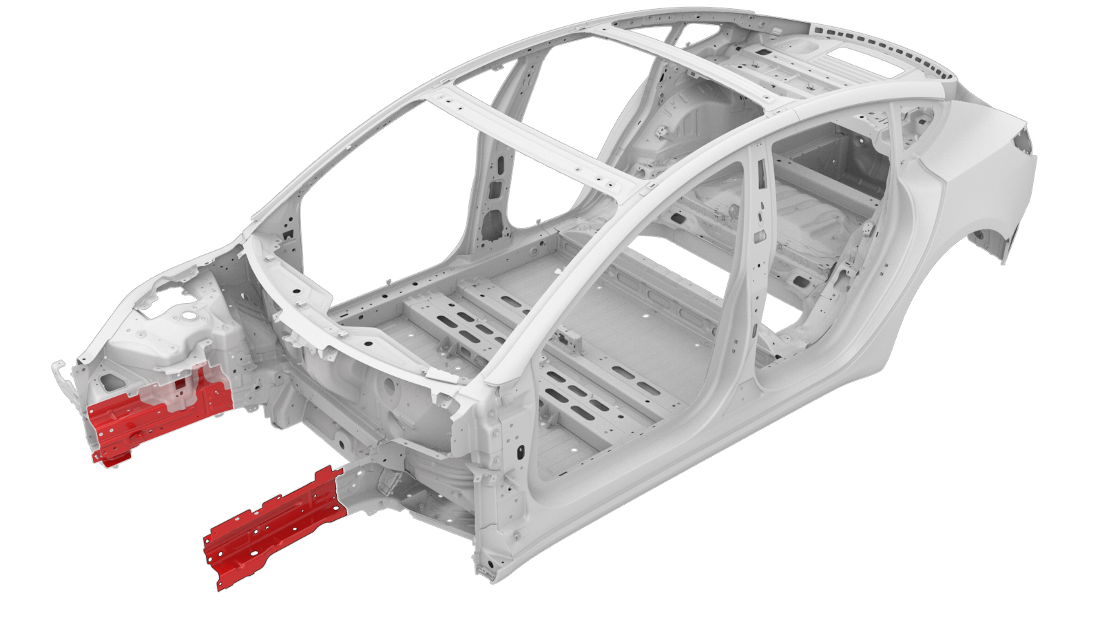
Front Frame Rail Inner (Large Front Section)
 Correction code:
10101001802
10101001702
NOTE:
Unless explicitly stated in the procedure, the above
correction code includes all Collision Repair and Service
repair work required to perform this procedure, including
the linked Collision Repair procedures and linked Service
procedures. Do not stack Collision Repair correction
codes unless explicitly told to do so. Depending
on the damage to the vehicle, additional repairs may be
required.
Correction code:
10101001802
10101001702
NOTE:
Unless explicitly stated in the procedure, the above
correction code includes all Collision Repair and Service
repair work required to perform this procedure, including
the linked Collision Repair procedures and linked Service
procedures. Do not stack Collision Repair correction
codes unless explicitly told to do so. Depending
on the damage to the vehicle, additional repairs may be
required.
Repair Information
- Review all collision repair general practices and safety documentation and wear the appropriate PPE (Personal Protective Equipment) before beginning this procedure.
- Depending on the damage to this component, it may be possible to repair this component. Refer to Front Frame Rail Inner Repair Guidelines for more information.
- Properly mount the vehicle on a frame bench when performing this procedure.
Parts List
| Quantity | Description | Image / Notes |
|---|---|---|
| 2 | M3 ASY - FRT RAIL INR PNL WITH BRACKETS (Front Frame Rail Inner) |
One Front Frame Rail Inner is needed for replacement and one is needed to make a backing plate. |
| 10 | High Strength Structural Rivet, 6.5 mm |
When ordering parts, refer to the Parts Catalog and enter the VIN of the vehicle being repaired to find the correct parts (and the part numbers) for the vehicle. Alternatively, use the search function in the Parts Catalog to find a specific part for the vehicle.
Repair Procedure
- Remove the ABS Modulator (Heat Pump) (Remove and Replace).
- Remove the Damper Assembly - Front - LH (RWD) (Remove and Replace).
- Remove the Hinge - Hood - LH (Remove and Replace).
- Remove the Reservoir - Windshield Washer (Remove and Replace).
- Remove the Front Upper Control Arm (FUCA) Mount - LH (Remove and Replace).
- Remove the Fender Assembly - Front - LH (Remove and Install).
- Remove the Hood (Remove and Install).
- Remove the Subframe Assembly - Front (Dual Motor) (Remove and Install).
- Remove the A/C Compressor, Supermanifold and Compressor to Supermanifold A/C Line (Heat Pump) (Remove and Replace).
- Remove the Radiator (Heat Pump) (Remove and Replace).
- Remove the Cooling System (Drain and Refill).
- Remove the Carrier - Front End (Heat Pump) (Remove and Replace).
- Remove the Ankle Catcher (Remove and Replace).
- Remove the Crush Can - Upper - Front - LH (Remove and Replace).
-
Remove the Front Frame Rail Inner Reinforcement (Complete).
-
Cut the original component at the indicated locations.
Reference Line/Point
Cut Line- A = 75 mm
-
Remove the original component.
- or Factory Spot Welds
-
Cut one of the new Front
Frame Rail Inner components as indicated below to make the new
component.
Reference Line/Point
Cut Line- A = 75 mm
-
Cut one of the new Front
Frame Rail Inner components as indicated below to make the backing
plate.
Reference Line/Point
Cut Line- B = 35 mm
- C = 115 mm
-
Cut the backing plate as
indicated.
Cut Line
-
Perform GMA welding.
WarningFailure to follow all welding safety precautions, including the use of personal protective equipment, could result in serious injury or property damage. Only technicians who have completed Tesla’s approved welding training are authorized to weld structural components on Tesla vehicles.WarningTo maintain vehicle crash integrity, use only approved welding wire and an approved GMA welder to perform GMA welding on Tesla vehicles. Refer to Approved Gas Metal Arc (GMA) Welders and Welding Wire for information on approved GMA welders and welding wire.CAUTIONDo not weld on a Tesla vehicle before performing the Vehicle Electrical Isolation Procedure (refer to the vehicle-specific Service Manual for more information on the Vehicle Electrical Isolation Procedure). Welding on a Tesla vehicle with an energized high or low voltage system might damage vehicle components.NoteBefore GMA welding, a test weld using material of the same gauge and type should be performed to make sure that the welding equipment settings produce a satisfactory joint.
-
Prepare for installation.
NoteAlign the holes in the Front Inner Front Subframe Bracket with the holes in the Front Frame Rail Inner.NoteA red X indicates a location where a factory-installed fastener is not being replaced. Secure this location using structural adhesive only.
- Reference Line/Point
- or High Strength Structural Rivets, 6.5 mm
- Installation Spot Weld
- D = 10 mm
- E = 8 mm
- Apply structural adhesive to the mating surfaces on the vehicle and the new component or components.
- Install the new component or components.
-
Perform resistance spot
welding.
WarningFailure to follow all welding safety precautions, including the use of personal protective equipment, could result in serious injury or property damage. Only technicians who have completed Tesla’s approved welding training are authorized to weld structural components on Tesla vehicles.CAUTIONDo not weld on a Tesla vehicle before performing the Vehicle Electrical Isolation Procedure (refer to the vehicle-specific Service Manual for more information on the Vehicle Electrical Isolation Procedure). Welding on a Tesla vehicle with an energized high or low voltage system might damage vehicle components.
-
Install the new Front Frame Rail Inner Reinforcement (Complete).
-
Install a new Front Trunk Bracket.
-
Install a new Front Subframe Mount (Front Inner).
-
Install the fasteners as indicated.
- Perform any necessary post-repair operations.
- Install the Crush Can - Upper - Front - LH (Remove and Replace).
- Install the Ankle Catcher (Remove and Replace).
- Install the Carrier - Front End (Heat Pump) (Remove and Replace).
- Install the Cooling System (Drain and Refill).
- Install the Radiator (Heat Pump) (Remove and Replace).
- Install the A/C Compressor, Supermanifold and Compressor to Supermanifold A/C Line (Heat Pump) (Remove and Replace).
- Install the Subframe Assembly - Front (Dual Motor) (Remove and Install).
- Install the Hood (Remove and Install).
- Install the Fender Assembly - Front - LH (Remove and Install).
- Install the Front Upper Control Arm (FUCA) Mount - LH (Remove and Replace).
- Install the Reservoir - Windshield Washer (Remove and Replace).
- Install the Hinge - Hood - LH (Remove and Replace).
- Install the Damper Assembly - Front - LH (RWD) (Remove and Replace).
- Install the ABS Modulator (Heat Pump) (Remove and Replace).