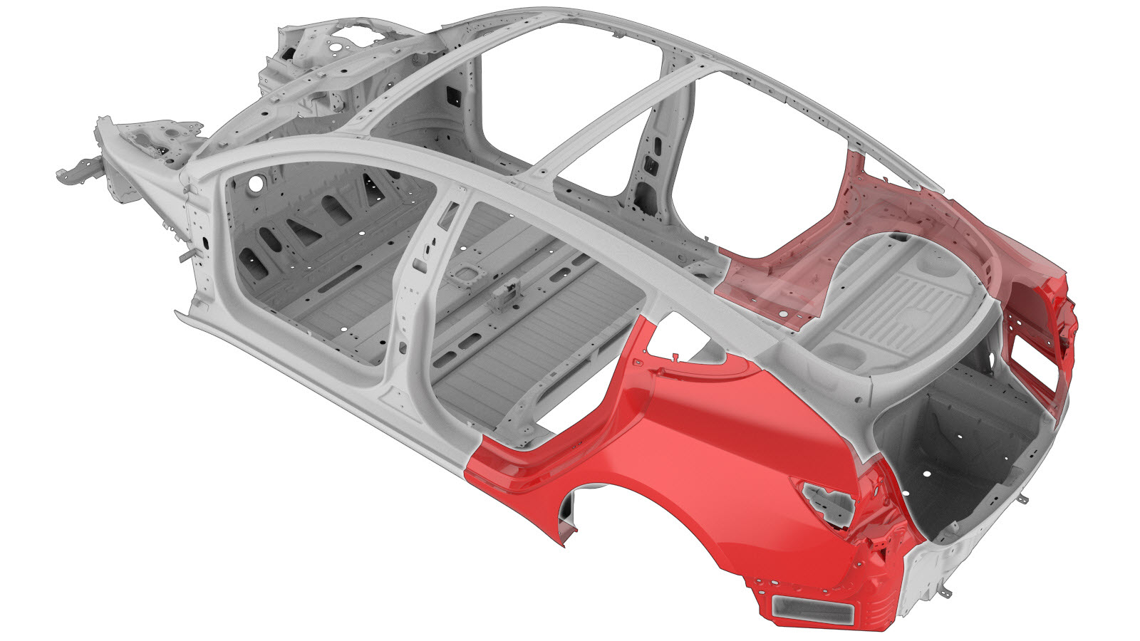
Quarter Outer Assembly (Without Upper Trough)
 Correction code:
10100121802
10100140402
NOTE:
Unless explicitly stated in the procedure, the above
correction code includes all Collision Repair and Service
repair work required to perform this procedure, including
the linked Collision Repair procedures and linked Service
procedures. Do not stack Collision Repair correction
codes unless explicitly told to do so. Depending
on the damage to the vehicle, additional repairs may be
required.
Correction code:
10100121802
10100140402
NOTE:
Unless explicitly stated in the procedure, the above
correction code includes all Collision Repair and Service
repair work required to perform this procedure, including
the linked Collision Repair procedures and linked Service
procedures. Do not stack Collision Repair correction
codes unless explicitly told to do so. Depending
on the damage to the vehicle, additional repairs may be
required.
Repair Information
- Review all collision repair general practices and safety documentation and wear the appropriate PPE (Personal Protective Equipment) before beginning this procedure.
- This procedure can be completed without using a frame bench.
- Any individual section or any combination of sections of the Body Side Outer Assembly can be replaced so long as the referenced cut lines from the Quarter Outer Assembly Section Descriptions portion of this document are used.
Using this Document
- Quarter Outer Assembly Section Descriptions provides information on
where and how to section the Quarter Outer Assembly (or subassemblies)
as necessary to replace damaged areas of the Quarter Outer assembly, or
to gain access to underlying parts of the vehicle structure. Use the
section descriptions to determine where to successfully section the Body
Side Outer Assembly as needed for the repair being performed.NoteSections of the Quarter Outer Assembly can be replaced individually or in any combination of sections so long as the referenced cut locations identified in this document are used.NoteMeasurements from bolt hole locations are from the center of the referenced holes unless stated differently in the section description.
- The Repair Procedure portion of this document contain the information necessary to replace the entire Quarter Outer Assembly. If replacing sections of the Quarter Outer (not the entire Quarter Outer Assembly), use the relevant portions of each step to determine which parts and fasteners are needed and the steps required to complete the repair.
Parts List
| Quantity | Description | Image / Notes |
|---|---|---|
| 1 | ASSEMBLY, REAR QUARTER OUTER (Rear Quarter Outer Assembly) | |
| 10 | Structural Bulb Rivet, 6.5 mm | |
| 12 LH or 11 RH | Flow Form Rivet S18 |
When ordering parts, refer to the Parts Catalog and enter the VIN of the vehicle being repaired to find the correct parts (and the part numbers) for the vehicle. Alternatively, use the search function in the Parts Catalog to find a specific part for the vehicle.
Quarter Outer Assembly Section Descriptions
| Quarter Outer Assembly Sectioning | ||
|---|---|---|
| The Quarter Outer Assembly is a single assembly, and can be replaced as a single repair, or instead of replacing the complete Quarter Outer Assembly, areas of the Quarter Outer can be replaced using portions of the complete Quarter Outer Assembly using the cut lines described in this document. | ||
|
|
| Quarter Outer Section Descriptions | Joint Descriptions |
|---|---|
|
Quarter Outer Skin Section Cut Line Warning Do not cut the Body Side Outer panel
directly over the underlying Rear Wheelhouse Reinforcement
panel. Reference Line/Point
Note Measure from the side of the hole as indicated in the
image. GMA Weld Note The gap
between the adjacent panels of the butt joint for this
section should be as small as possible to maximize joint
strength. Note Fill gaps
in welded seams using structural adhesive and seal any open
seams after welding. |
|
|
Dogleg Section Cut Line Reference Line/Point
Note Measure from the side of the hole as indicated in the
image. Warning Do not cut the steel Body Side Outer panel
directly over the underlying aluminum components. The
underlying components (highlighted in red) include both the
Rear Wheelhouse Reinforcement and the Rear Wheel Arch
Assembly. GMA Weld Note The gap
between the adjacent panels of the butt joint for this
section should be as small as possible to maximize joint
strength. Note Seal all open seams after welding. |
|
|
Rear Sill Section Cut Line Reference Line/Point
GMA Weld Note The cut can
be made within 50 mm. to either side of the specified cut
line. Note The gap
between the adjacent panels of the butt joint for this
section should be as small as possible to maximize joint
strength. Note Seal all open seams after welding. |
|
|
Rear Roof Rail Section Note If the repair area includes any portion of the Roof Rail,
do not use this procedure; instead, refer to the Body Side Outer. |
Repair Procedure
- Remove the Door - Rear - LH (Remove and Install).
- Remove the Door Assembly - Charge Port (NA) (Harness Type) (Remove and Replace).
- Remove the Charge Port (Busbar Type) (NACS) (Remove and Replace).
- Remove the Air Extractor - LH (Remove and Replace).
- Remove the Seatbelt - 2nd Row - LH (Remove and Replace).
- Remove the Cover - Rocker Panel - Lower - LH (Remove and Replace).
- Remove the Wheel Arch Liner - Rear - LH (Remove and Replace).
- Remove the Trim - Package Tray (Remove and Replace).
- Remove the Trim - Sill Panel - Rear - LH (Remove and Replace).
- Remove the Carpet - Rear Trunk (1-Piece) (Remove and Replace).
- Remove the Trim - Side - Trunk - LH (Remove and Replace).
- Remove the Glass - Body - Rear Quarter - LH (Remove and Install).
- Remove the Striker - Door - Rear - LH (Remove and Replace).
- Remove the Trunk (Remove and Install).
- Remove the Bracket - Rear Wing - LH (Remove and Replace).
- Remove the Bumper Beam - Rear (Remove and Replace).
-
Remove
the Upper Trough from the Rear Quarter Outer Assembly service
part.
or Factory Spot Weldsor Drill through factory spot weldsNoteWhen drilling out spot welds, use a drill bit that creates a hole correctly sized for the fastener that will replace the spot weld.
-
Remove the original component.
or Factory Spot WeldsNoteDo not remove spot welds in the areas highlighted with yellow circles.
or Factory SPRs
or Drill through factory spot weldsNoteWhen drilling out spot welds, use a drill bit that creates a hole correctly sized for the fastener that will replace the spot weld. -
Separate the Wheel Arch
flange.
-
Prepare for installation.
NoteA red X indicates a location where a factory-installed fastener is not being replaced. Secure this location using structural adhesive only.
or Installation Spot Welds
or Steel Plug Welds
GMA Weld
- Apply structural adhesive to the mating surfaces on the vehicle and the new component or components.
-
Install the new component or components.
NoteThe Body Side Outer lower flange is secured using structural adhesive only.
- Fold over the wheel arch flange.
-
Perform resistance spot
welding.
or Installation Spot WeldsWarningFailure to follow all welding safety precautions, including the use of personal protective equipment, could result in serious injury or property damage. Only technicians who have completed Tesla’s approved welding training are authorized to weld structural components on Tesla vehicles.CAUTIONDo not weld on a Tesla vehicle before performing the Vehicle Electrical Isolation Procedure (refer to the vehicle-specific Service Manual for more information on the Vehicle Electrical Isolation Procedure). Welding on a Tesla vehicle with an energized high or low voltage system might damage vehicle components.
-
Perform GMA welding.
or Steel Plug Welds
GMA Weld
WarningFailure to follow all welding safety precautions, including the use of personal protective equipment, could result in serious injury or property damage. Only technicians who have completed Tesla’s approved welding training are authorized to weld structural components on Tesla vehicles.WarningTo maintain vehicle crash integrity, use only approved welding wire and an approved GMA welder to perform GMA welding on Tesla vehicles. Refer to Approved Gas Metal Arc (GMA) Welders and Welding Wire for information on approved GMA welders and welding wire.CAUTIONDo not weld on a Tesla vehicle before performing the Vehicle Electrical Isolation Procedure (refer to the vehicle-specific Service Manual for more information on the Vehicle Electrical Isolation Procedure). Welding on a Tesla vehicle with an energized high or low voltage system might damage vehicle components.NoteBefore GMA welding, a test weld using material of the same gauge and type should be performed to make sure that the welding equipment settings produce a satisfactory joint. -
Fill the indicated seam with
structural adhesive.
-
For the plug weld circled in red, seal the hole left from drilling the
backside of the plug weld.
-
Fold over the Wheel Arch
flange.
- If the original Charge Port Housing had a ground wire or harness attachment point, drill a hole in the new Charge Port Housing for a Rivnut or a retainer clip. (Refer to the Charge Port Housing Assembly procedure for information about the size and location of the hole.)
- Perform any necessary post-repair operations.
- Install the Bumper Beam - Rear (Remove and Replace).
- Install the Bracket - Rear Wing - LH (Remove and Replace).
- Install the Trunk (Remove and Install).
- Install the Striker - Door - Rear - LH (Remove and Replace).
- Install the Glass - Body - Rear Quarter - LH (Remove and Install).
- Install the Trim - Side - Trunk - LH (Remove and Replace).
- Install the Carpet - Rear Trunk (1-Piece) (Remove and Replace).
- Install the Trim - Sill Panel - Rear - LH (Remove and Replace).
- Install the Trim - Package Tray (Remove and Replace).
- Install the Wheel Arch Liner - Rear - LH (Remove and Replace).
- Install the Cover - Rocker Panel - Lower - LH (Remove and Replace).
- Install the Seatbelt - 2nd Row - LH (Remove and Replace).
- Install the Air Extractor - LH (Remove and Replace).
- Install the Charge Port (Busbar Type) (NACS) (Remove and Replace).
- Install the Door Assembly - Charge Port (NA) (Harness Type) (Remove and Replace).
- Install the Door - Rear - LH (Remove and Install).