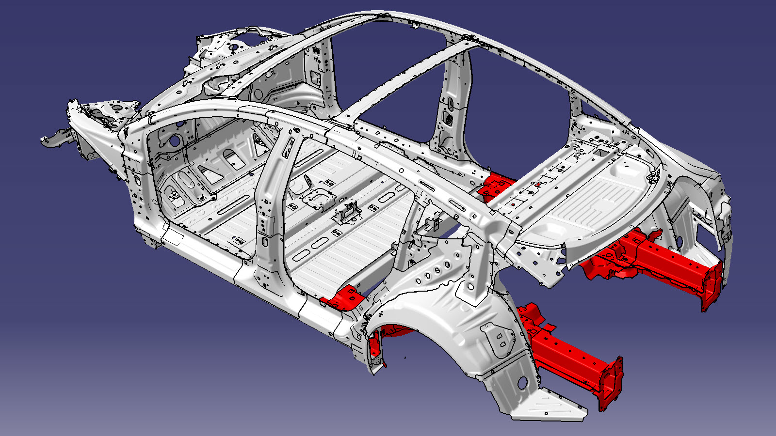
Rear Node (Complete)
 Correction code:
10101813302
10101813402
NOTE:
Unless explicitly stated in the procedure, the above
correction code includes all Collision Repair and Service
repair work required to perform this procedure, including
the linked Collision Repair procedures and linked Service
procedures. Do not stack Collision Repair correction
codes unless explicitly told to do so. Depending
on the damage to the vehicle, additional repairs may be
required.
Correction code:
10101813302
10101813402
NOTE:
Unless explicitly stated in the procedure, the above
correction code includes all Collision Repair and Service
repair work required to perform this procedure, including
the linked Collision Repair procedures and linked Service
procedures. Do not stack Collision Repair correction
codes unless explicitly told to do so. Depending
on the damage to the vehicle, additional repairs may be
required.
Repair Information
- Review all collision repair general practices and safety documentation and wear the appropriate PPE (Personal Protective Equipment) before beginning this procedure.
- Properly mount the vehicle on a frame bench when performing this procedure.
Parts List
| Quantity | Description | Image / Notes |
|---|---|---|
| 1 | ASSEMBLY - REAR FRAMERAIL COMPLETE (Rear Node - Complete) | |
| 12 | High Strength Structural Rivet, 6.5 mm | |
| 17 | Structural Bulb Rivet, 6.5 mm | |
| 4 | Countersunk Rivet, 4.8 mm Long | |
| 2 | Structural Countersunk Rivet, 6.5 mm | |
| 1 | Structural Rivet, 6.5 mm Medium | |
| 2 | Rivet, 4.8 mm | |
| 4 | Countersunk Rivet, 4.8 mm Short | |
| 13 | Flow Form Rivet S18 | |
| 1 | Flow Form Rivet S08 | |
| 2 | Flow Form Rivet S28 | |
| 10 | Flow Form Rivet S38 | |
| 2 | Bolt, hex-head, BOLT & WSHR, HX, M8x23.5,STL[109],PTC,ZNNI | Tesla part number 1063260-00-C. |
When ordering parts, refer to the Parts Catalog and enter the VIN of the vehicle being repaired to find the correct parts (and the part numbers) for the vehicle. Alternatively, use the search function in the Parts Catalog to find a specific part for the vehicle.
Repair Procedure
- Remove the Glass - Body - Rear Quarter - LH (Remove and Install).
- Remove the Trim - Side - Trunk - RH (Remove and Replace).
- Remove the Trim - Side - Trunk - LH (Remove and Replace).
- Remove the Bracket - Taillight - LH (Remove and Replace).
- Remove the Bumper Beam - Rear (Remove and Replace).
- Remove the ECU - Charge Port (Remove and Replace).
- Remove the Busbars - Charge Port to HV Battery (NACS) (Remove and Replace).
- Remove the Subwoofer (Remove and Replace).
- Remove the HV Battery (RWD) (Remove and Install).
- Remove the Subframe Assembly - Rear (Remove and Install).
- Remove the Brake Lines - Rear - RH to Sill (Remove and Replace).
- Remove the Brake Lines - LH Sill (Remove and Replace).
-
Remove the Rear Frame Rail End Plate.
-
Remove the Trunk Floor Assembly (Complete).
-
Remove the Rear Motor Cover Floor.
-
Remove the Rear Subframe Lower Crossmember.
-
Remove the Third Row Seat Crossmember (Lower).
-
Remove the Heelboard Crossmember.
-
Remove the necessary portion
of the Body Side Outer to expose the underlying component being replaced.
-
Remove the original component.
or Factory Spot Welds
or Drill through factory spot weldsNoteWhen drilling out spot welds, use a drill bit that creates a hole correctly sized for the fastener that will replace the spot weld.or Factory SPRs
or Bolts
-
Prepare for installation.
NoteA red X indicates a location where a factory-installed fastener is not being replaced. Secure this location using structural adhesive only.
or High Strength Structural Rivets, 6.5 mm
or Structural Bulb Rivets, 6.5 mm- A = 12 mm.
- B = 10 mm.
or Structural Countersunk Rivets, 6.5 mm
or Countersunk Rivets, 4.8 mm Short
or Countersunk Rivets, 4.8 mm Long
or Structural Rivets, 6.5 mm Medium
or Bolts
GMA WeldNoteEach GMA weld is 20 mm in length. - Apply structural adhesive to the mating surfaces on the vehicle and the new component or components.
-
Install the new component or components.
Torque the hex-head bolts to 24 Nm.
-
Perform GMA welding.
GMA WeldNoteEach GMA weld is 20 mm in length.WarningFailure to follow all welding safety precautions, including the use of personal protective equipment, could result in serious injury or property damage. Only technicians who have completed Tesla’s approved welding training are authorized to weld structural components on Tesla vehicles.WarningTo maintain vehicle crash integrity, use only approved welding wire and an approved GMA welder to perform GMA welding on Tesla vehicles. Refer to Approved Gas Metal Arc (GMA) Welders and Welding Wire for information on approved GMA welders and welding wire.CAUTIONDo not weld on a Tesla vehicle before performing the Vehicle Electrical Isolation Procedure (refer to the vehicle-specific Service Manual for more information on the Vehicle Electrical Isolation Procedure). Welding on a Tesla vehicle with an energized high or low voltage system might damage vehicle components.NoteBefore GMA welding, a test weld using material of the same gauge and type should be performed to make sure that the welding equipment settings produce a satisfactory joint.
-
Install the Heelboard Crossmember.
-
Install the fasteners as indicated.
-
Install the portion of the
Body Side Outer
that was removed to expose the component being replaced. .
-
Install the fasteners as indicated.
- C = 93 mm.
- D = 8 mm.
-
Install the Third Row Seat Crossmember (Lower).
-
Install the Rear Subframe Lower Crossmember.
-
Install the Rear Frame Rail End Plate.
-
Install the new Rear Body Panel.
- Perform any necessary post-repair operations.
- Install the Brake Lines - LH Sill (Remove and Replace).
- Install the Brake Lines - Rear - RH to Sill (Remove and Replace).
- Install the Subframe Assembly - Rear (Remove and Install).
- Install the HV Battery (RWD) (Remove and Install).
- Install the Subwoofer (Remove and Replace).
- Install the Busbars - Charge Port to HV Battery (NACS) (Remove and Replace).
- Install the ECU - Charge Port (Remove and Replace).
- Install the Bumper Beam - Rear (Remove and Replace).
- Install the Bracket - Taillight - LH (Remove and Replace).
- Install the Trim - Side - Trunk - LH (Remove and Replace).
- Install the Trim - Side - Trunk - RH (Remove and Replace).
- Install the Glass - Body - Rear Quarter - LH (Remove and Install).