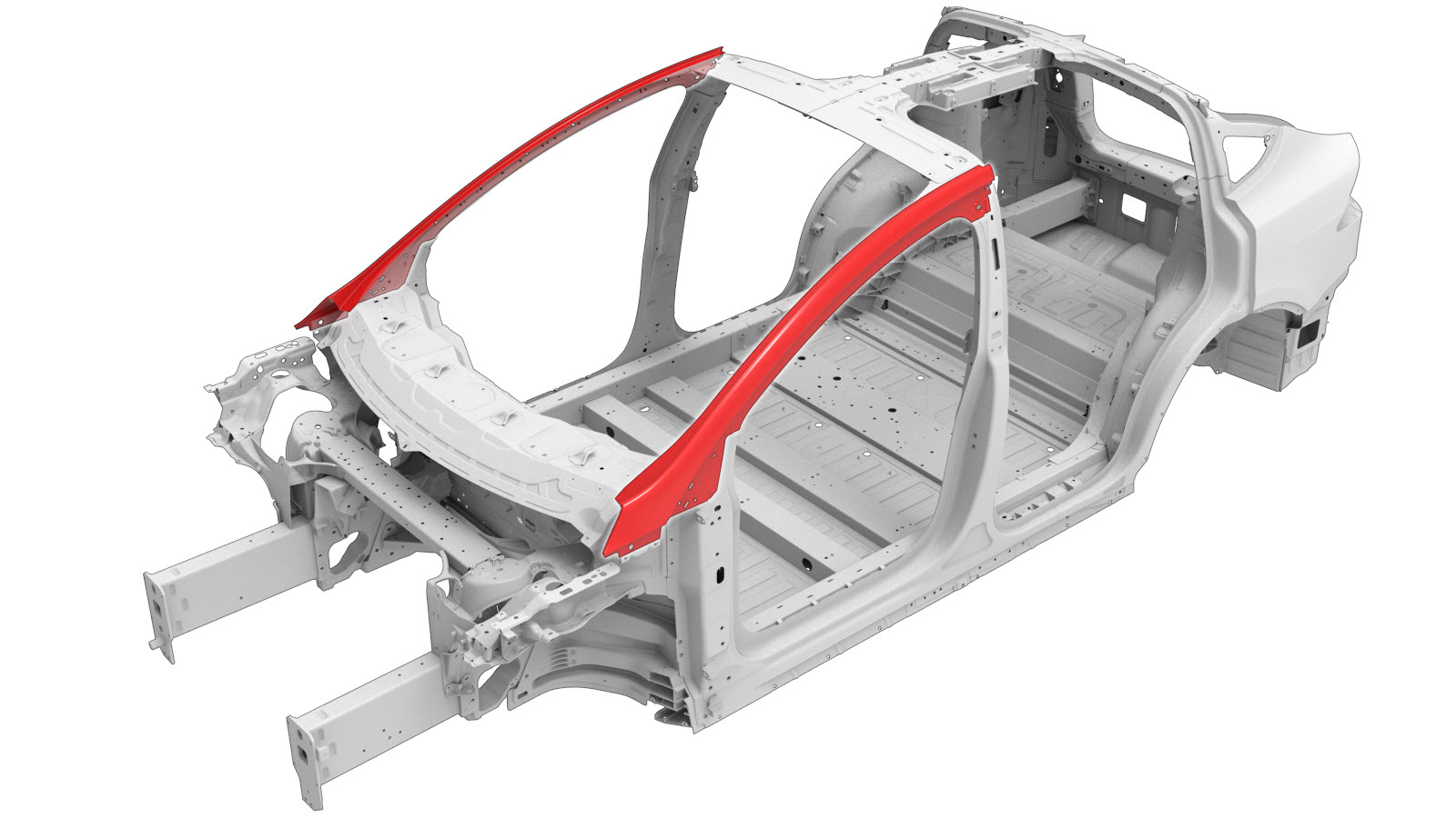
A-Pillar Outer
 Correction code:
10100127302
10100127402
NOTE:
Unless explicitly stated in the procedure, the above
correction code includes all Collision Repair and Service
repair work required to perform this procedure, including
the linked Collision Repair procedures and linked Service
procedures. Do not stack Collision Repair correction
codes unless explicitly told to do so. Depending
on the damage to the vehicle, additional repairs may be
required.
Correction code:
10100127302
10100127402
NOTE:
Unless explicitly stated in the procedure, the above
correction code includes all Collision Repair and Service
repair work required to perform this procedure, including
the linked Collision Repair procedures and linked Service
procedures. Do not stack Collision Repair correction
codes unless explicitly told to do so. Depending
on the damage to the vehicle, additional repairs may be
required.
Repair Information
- Any individual section or any combination of sections of the Body Side Outer Assembly can be replaced so long as the referenced cut lines from the A-Pillar Outer Section Descriptions portion of this document are used.
- Review all collision repair general practices and safety documentation and wear the appropriate PPE (Personal Protective Equipment) before beginning this procedure.
- This procedure can be completed without using a frame bench.
Using this Document
- A-Pillar Outer Section Descriptions provide
information on where and how to section the A-Pillar Outer as necessary to replace
damaged areas of the A-Pillar Outer, or to gain access to underlying parts of the
vehicle structure. Use the section descriptions to determine where to successfully
section the A-Pillar Outer as needed for the repair being performed.NoteMeasurements from bolt hole locations are from the center of the referenced holes unless stated differently in the section description.
- The Repair Procedure portion of this document contain the information necessary to replace the entire A-Pillar Outer. If replacing a section of the A-Pillar Outer (not the entire A-Pillar Outer), use the relevant portions of each step to determine which parts and fasteners are needed and the steps required to complete the repair.
Parts List
| Quantity | Description | Image / Notes |
|---|---|---|
| If replacing the complete A-Pillar Outer: 1 If replacing a section of the A-Pillar Outer: 2 |
ASY, A-PILLAR OTR, SVC (A-Pillar Outer) | |
| 2 | Countersunk Rivet, 4.8 mm Short | |
| 5 | Rivet, 4.8 mm | |
| 4 | Flow Form Rivet S28 | |
| 13 | Flow Form Rivet S38 |
When ordering parts, refer to the Parts Catalog and enter the VIN of the vehicle being repaired to find the correct parts (and the part numbers) for the vehicle. Alternatively, use the search function in the Parts Catalog to find a specific part for the vehicle.
A-Pillar Outer Section Descriptions
| A-Pillar Outer Sectioning | |
|---|---|
| A-Pillar Outer (Complete) | A-Pillar Outer Sections |
|
|
|
|
Alternatively, instead of replacing the complete A-Pillar Outer, either the upper or lower section can be replaced using a portion of the complete A-Pillar Outer using the cut line described in this document. |
|
| A-Pillar Outer Section Descriptions | |
|---|---|
|
Cut Line Reference Line/Point
Note If space is
available behind the butt joint, create and install a
backing plate. or Aluminum Plug Welds GMA Weld |
|
Repair Procedure
- If replacing a section of the A-Pillar Outer: Mark the cut line as described in A-Pillar Outer Section Descriptions.
-
Remove the original component.
or Factory Spot Welds
or Factory SPRs
- If replacing a section of the A-Pillar Outer: create and install a backing plate as described in A-Pillar Outer Section Descriptions.
-
Prepare for installation.
NoteA red X indicates a location where a factory-installed fastener is not being replaced. Secure this location using structural adhesive only.or Flow Form Rivets, S38
- A = 9 mm.
or Rivets, 4.8 mm- B = 60 mm.
- Apply structural adhesive to the mating surfaces on the vehicle and the new component or components.
- Install the new component or components.
-
If replacing a section of the A-Pillar
Outer:
GMA weld the butt joint between the sections.
GMA WeldWarningFailure to follow all welding safety precautions, including the use of personal protective equipment, could result in serious injury or property damage. Only technicians who have completed Tesla’s approved welding training are authorized to weld structural components on Tesla vehicles.WarningTo maintain vehicle crash integrity, use only approved welding wire and an approved GMA welder to perform GMA welding on Tesla vehicles. Refer to Approved Gas Metal Arc (GMA) Welders and Welding Wire for information on approved GMA welders and welding wire.CAUTIONDo not weld on a Tesla vehicle before performing the Vehicle Electrical Isolation Procedure (refer to the vehicle-specific Service Manual for more information on the Vehicle Electrical Isolation Procedure). Welding on a Tesla vehicle with an energized high or low voltage system might damage vehicle components.NoteBefore GMA welding, a test weld using material of the same gauge and type should be performed to make sure that the welding equipment settings produce a satisfactory joint.
- Perform any necessary post-repair operations.