Quarter Outer Assembly (Without Upper Trough)
 Correction code:
10100132902,
10100133002
NOTE:
Unless explicitly stated in the procedure, the above
correction code includes all Collision Repair and Service
repair work required to perform this procedure, including
the linked Collision Repair procedures and linked Service
procedures. Do not stack Collision Repair correction
codes unless explicitly told to do so. Depending
on the damage to the vehicle, additional repairs may be
required.
Correction code:
10100132902,
10100133002
NOTE:
Unless explicitly stated in the procedure, the above
correction code includes all Collision Repair and Service
repair work required to perform this procedure, including
the linked Collision Repair procedures and linked Service
procedures. Do not stack Collision Repair correction
codes unless explicitly told to do so. Depending
on the damage to the vehicle, additional repairs may be
required.
Repair Information
- Any individual section or any combination of sections of the Body Side Outer Assembly can be replaced so long as the referenced cut lines from the Sectioning Guidelines portion of this document are used.
- Review all collision repair general practices and safety documentation and wear the appropriate PPE (Personal Protective Equipment) before beginning this procedure.
- This procedure can be completed without using a frame bench.
Using this Document
- Sectioning Guidelines provides information on where and how to section the Quarter Outer Assembly as necessary to replace damaged areas of the Quarter Outer assembly, or to gain access to underlying parts of the vehicle structure. Use the guidelines to determine where to successfully section the Quarter Outer Assembly as needed for the repair being performed.
- The Repair Procedure portion of this document contain the information necessary to replace the entire Quarter Outer Assembly. If replacing sections of the Quarter Outer (not the entire Quarter Outer Assembly), use the relevant portions of each step to determine which parts and fasteners are needed and the steps required to complete the repair.
Parts List
| Quantity | Description | Image / Notes |
|---|---|---|
| 1 | ASSEMBLY - REAR QUARTER OUTER (Rear Quarter Outer Assembly) | |
| 5 | Structural Bulb Rivet, 6.5 mm | |
| 11 | Flow Form Rivet S18 |
When ordering parts, refer to the Parts Catalog and enter the VIN of the vehicle being repaired to find the correct parts (and the part numbers) for the vehicle. Alternatively, use the search function in the Parts Catalog to find a specific part for the vehicle.
Sectioning Guidelines
- If a section repair requires the removal or installation of additional panels or assemblies, perform the necessary procedures using the specific repair procedure for each panel or assembly.
- It is allowable to cut through a clearance hole or a non functional hole (exterior trim hole), as described below.
- Do not cut within 25 mm. of the center of a bolt hole.
- Sections do not require fasteners at butt joints unless specifically indicated.
- A backing plate may be installed at a butt joint between sections (as described in create and install backing plates).
- Gaps between panels of butt joints should be as small as possible to maximize joint strength.
- GMA weld section butt joints.
- Seal all open seams after welding.
- If a butt joint includes a flange, do not weld on the flange (flanges are secured using only structural adhesive).
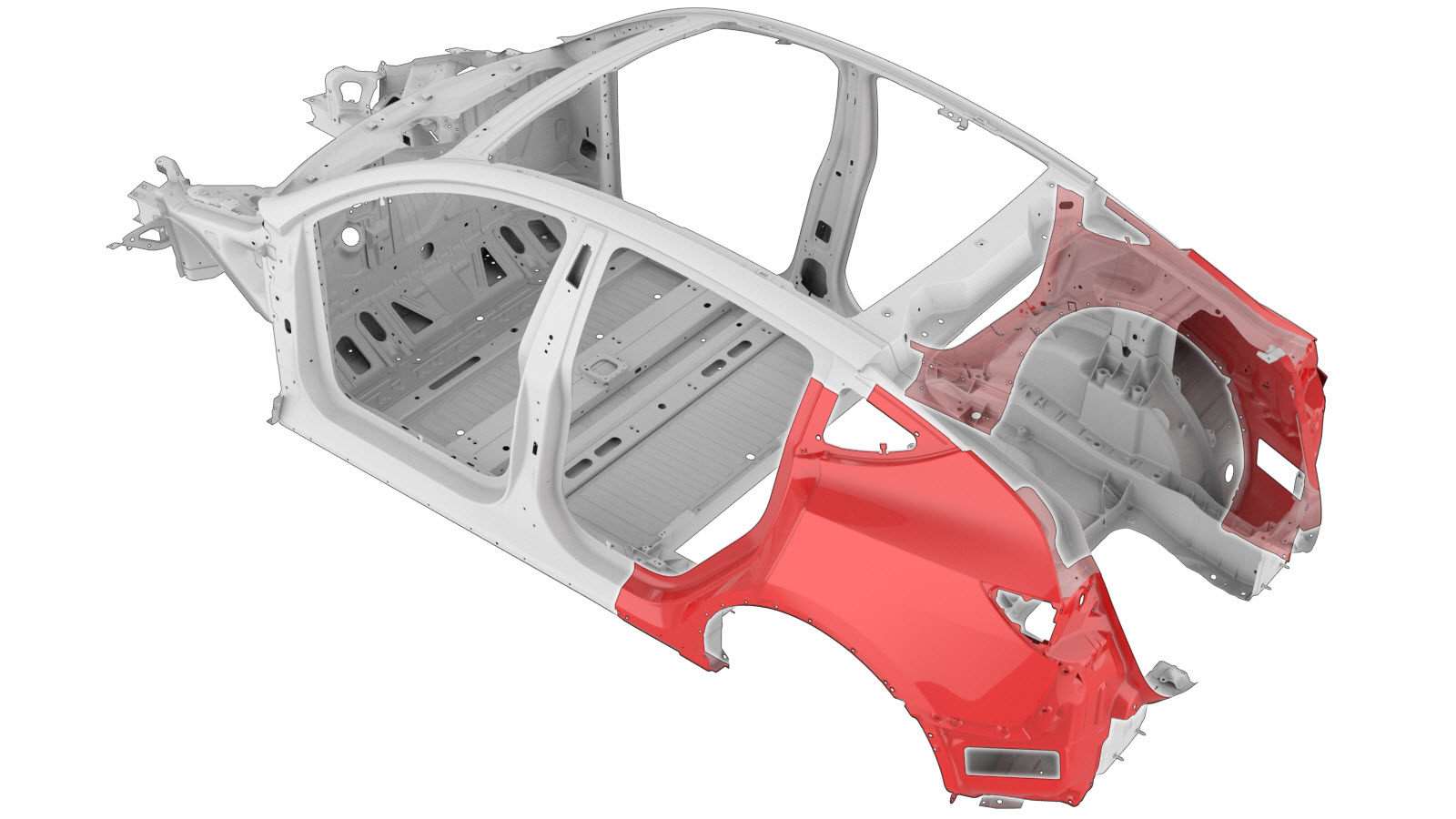
The image below shows the Quarter Outer Assembly sections. The colored areas indicate if sectioning is allowed. Compare the damaged area of the vehicle's Quarter Outer Assembly to the image below, then use the repair criteria corresponding to the color of the highlighted area to find the criteria to use to determine if the damaged area of the component can be sectioned.
| Quarter Outer Assembly Sectioning | |
|---|---|
Based on the colors used in the image above, the allowed repairs are as follows:
| Area Color | Area Repairability |
|---|---|
| Green areas: | Sectioning is allowed in these areas. |
| Yellow areas: | Sectioning is allowed in these areas. Foam is located behind
the panel. Note If sectioning in
this area, remove the foam and then clean the area to avoid weld
contamination. |
| Red areas: | Sectioning is not allowed. |
Repair Procedure
- Remove the Seal - Trunk (Remove and Replace).
- Remove the Air Extractor - LH (Remove and Replace).
- Remove the Striker - Door - Rear - LH (Remove and Replace).
- Remove the Seal - Body - Side - Rear - Primary - LH (Remove and Replace).
- Remove the Vehicle HV Disablement Procedure.
- Remove the Wheel Arch Liner - Rear - LH (Non-Structural Pack) (Remove and Replace).
- Remove the Panel Assembly - Rear (Remove and Replace).
- Remove the Carrier - Rocker Panel - LH (Remove and Replace).
- Remove the Door Assembly - Charge Port (NA) (Remove and Replace).
- Remove the Bracket - Rear Wing - LH (Remove and Replace).
- Remove the Bracket - Taillight - LH (Remove and Replace).
- Remove the Brightwork - Upper - LH (Remove and Replace).
- Remove the Door - Rear - LH (Remove and Install).
- Remove the Liftgate Assembly (Remove and Install).
- Remove the Glass - Body - Rear Quarter - LH (Remove and Install).
- Remove the Seatbelt - 2nd Row - LH (5 Seat) (Remove and Replace).
-
Remove the Upper
Trough from the Rear Quarter Outer Assembly service part.
- or Drill through factory spot welds
NoteWhen drilling out spot welds, use a drill bit that creates a hole correctly sized for the fastener that will replace the spot weld.- or Factory Spot Welds
-
Remove the Upper
Trough from the Rear Quarter Outer Assembly service part
- or Factory Spot Welds
-
Remove the Upper
Trough from the Rear Quarter Outer Assembly service part
- or Factory Spot Welds
-
Remove the Upper
Trough from the Rear Quarter Outer Assembly service part
- or Factory Spot Welds
-
Remove the original component.
- or Factory Spot Welds
- or Factory SPRs
-
Remove the original component.
- or Drill through factory spot welds
NoteWhen drilling out spot welds, use a drill bit that creates a hole correctly sized for the fastener that will replace the spot weld.- or Factory Spot Welds
- or Factory SPRs
-
Remove the original component.
- or Drill through factory spot welds
NoteWhen drilling out spot welds, use a drill bit that creates a hole correctly sized for the fastener that will replace the spot weld.- or Factory Spot Welds
-
Remove the original component.
- or Factory Spot Welds
-
Remove the original component.
- or Factory Spot Welds
-
If the Striker Reinforcement panel on
the service assembly does not already have a cutout for the Wheel Arch Baffle, cut the
Striker Reinforcement panel as indicated.
NoteCut only the Striker Reinforcement panel; do not cut the underlying panel.
- Reference Line/Point
- Cut Line A = 14 mm B = 6 mm
-
Prepare for installation.
NoteA red X indicates a location where a factory-installed fastener is not being replaced. Secure this location using structural adhesive only.
- or Structural Bulb Rivets, 6.5 mm
- or Flow Form Rivets, S18
- GMA Weld
- or Installation Spot Welds
-
Prepare for installation.
NoteA red X indicates a location where a factory-installed fastener is not being replaced. Secure this location using structural adhesive only.
- or Structural Bulb Rivets, 6.5 mm
- or Flow Form Rivets, S18
- GMA Weld
- or Installation Spot Welds
- or Steel Plug Welds
-
Prepare for installation.
NoteA red X indicates a location where a factory-installed fastener is not being replaced. Secure this location using structural adhesive only.
- or Flow Form Rivets, S18
- or Installation Spot Welds
- or Steel Plug Welds
-
Prepare for installation.
NoteA red X indicates a location where a factory-installed fastener is not being replaced. Secure this location using structural adhesive only.
- or Flow Form Rivets, S18
- or Installation Spot Welds
- or Steel Plug Welds
- Apply structural adhesive to the mating surfaces on the vehicle and the new component or components.
- Install the new component or components.
-
Perform resistance spot
welding.
- or Installation Spot Welds
WarningFailure to follow all welding safety precautions, including the use of personal protective equipment, could result in serious injury or property damage. Only technicians who have completed Tesla’s approved welding training are authorized to weld structural components on Tesla vehicles.CAUTIONDo not weld on a Tesla vehicle before performing the Vehicle Electrical Isolation Procedure (refer to the vehicle-specific Service Manual for more information on the Vehicle Electrical Isolation Procedure). Welding on a Tesla vehicle with an energized high or low voltage system might damage vehicle components. -
Perform GMA welding.
- or Steel Plug Welds
- GMA Weld
WarningFailure to follow all welding safety precautions, including the use of personal protective equipment, could result in serious injury or property damage. Only technicians who have completed Tesla’s approved welding training are authorized to weld structural components on Tesla vehicles.WarningTo maintain vehicle crash integrity, use only approved welding wire and an approved GMA welder to perform GMA welding on Tesla vehicles. Refer to Approved Gas Metal Arc (GMA) Welders and Welding Wire for information on approved GMA welders and welding wire.CAUTIONDo not weld on a Tesla vehicle before performing the Vehicle Electrical Isolation Procedure (refer to the vehicle-specific Service Manual for more information on the Vehicle Electrical Isolation Procedure). Welding on a Tesla vehicle with an energized high or low voltage system might damage vehicle components.NoteBefore GMA welding, a test weld using material of the same gauge and type should be performed to make sure that the welding equipment settings produce a satisfactory joint. - Perform any necessary post-repair operations.
- Install the Seatbelt - 2nd Row - LH (5 Seat) (Remove and Replace).
- Install the Glass - Body - Rear Quarter - LH (Remove and Install).
- Install the Liftgate Assembly (Remove and Install).
- Install the Door - Rear - LH (Remove and Install).
- Install the Brightwork - Upper - LH (Remove and Replace).
- Install the Bracket - Taillight - LH (Remove and Replace).
- Install the Bracket - Rear Wing - LH (Remove and Replace).
- Install the Door Assembly - Charge Port (NA) (Remove and Replace).
- Install the Carrier - Rocker Panel - LH (Remove and Replace).
- Install the Panel Assembly - Rear (Remove and Replace).
- Install the Wheel Arch Liner - Rear - LH (Non-Structural Pack) (Remove and Replace).
- Install the Vehicle HV Disablement Procedure.
- Install the Seal - Body - Side - Rear - Primary - LH (Remove and Replace).
- Install the Striker - Door - Rear - LH (Remove and Replace).
- Install the Air Extractor - LH (Remove and Replace).
- Install the Seal - Trunk (Remove and Replace).