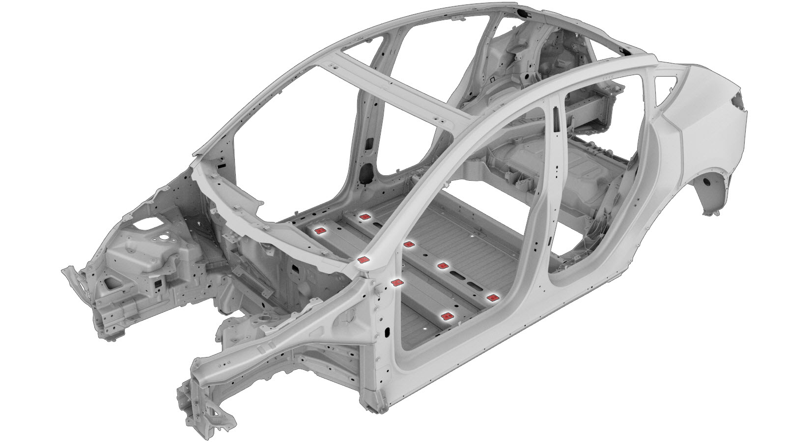
Front Seat Mount Reinforcements
 Correction code:
10100302102
NOTE:
Unless explicitly stated in the procedure, the above
correction code includes all Collision Repair and Service
repair work required to perform this procedure, including
the linked Collision Repair procedures and linked Service
procedures. Do not stack Collision Repair correction
codes unless explicitly told to do so. Depending
on the damage to the vehicle, additional repairs may be
required.
Correction code:
10100302102
NOTE:
Unless explicitly stated in the procedure, the above
correction code includes all Collision Repair and Service
repair work required to perform this procedure, including
the linked Collision Repair procedures and linked Service
procedures. Do not stack Collision Repair correction
codes unless explicitly told to do so. Depending
on the damage to the vehicle, additional repairs may be
required.
Repair Information
- Review all collision repair general practices and safety documentation and wear the appropriate PPE (Personal Protective Equipment) before beginning this procedure.
- This procedure can be completed without using a frame bench.
Parts List
| Quantity | Description | Image / Notes |
|---|---|---|
| 1 | ASY – FSF SEAT MOUNT REINF (Front Seat Mount Reinforcement – Front and Rear Outboard) |
Note This part replaces all Front
Seat Mount Front reinforcements and the Front Seat Mount Rear Outboard
reinforcements. It does not replace the Front Seat Mount Rear Inboard
reinforcements. |
| 1 | MY ASY – REINF FSR CROSSMEMBER INBOARD SVC E-COATED (Front Seat Mount Reinforcement – Rear Inboard) |
Note This part replaces only the
Front Seat Mount Rear Inboard reinforcements: it does not replace the Front Seat
Mount Front reinforcements or the Front Seat Mount Rear Outboard
reinforcements. |
| 1 | M3 FLOOR PANEL PATCH |
When ordering parts, refer to the Parts Catalog and enter the VIN of the vehicle being repaired to find the correct parts (and the part numbers) for the vehicle. Alternatively, use the search function in the Parts Catalog to find a specific part for the vehicle.
Repair Procedure
- Remove the Carpet - Rear (Remove and Replace).
- Remove the HV Battery (AWD) (Non-Structural Pack) (Remove and Install).
- Remove the Carpet - Interior Complete (Remove and Replace).
- Remove the .
- Remove the HV Battery (AWD) (Non-Structural Pack) (Remove and Install).
-
For the seat mount reinforcement being
replaced, cut a hole in the underside of the floor panel to access the damaged
component.
Front mounts:
- Reference Line/PointA = 564 mmB = 562 mmC = 104 mmD = 253 mmE = 56 mm
NoteDo not cut the floor panel under any mount that is not being replaced.NoteDo not damage the floor cross members when cutting the floor panel. -
For the seat mount reinforcement being replaced, cut a hole in the underside of the
floor panel to access the damaged component.
Rear outboard mounts:
- Reference Line/PointF = 227 mmG = 433 mmH = 60 mm
NoteDo not cut the floor panel under any mount that is not being replaced.NoteDo not damage the floor cross members when cutting the floor panel. -
For the seat mount reinforcement being replaced, cut a hole in the underside of the
floor panel to access the damaged component.
Rear inboard mounts:
- Reference Line/PointI = 128 mmJ = 433 mmK = 60 mm
NoteDo not cut the floor panel under any mount that is not being replaced.NoteDo not damage the floor cross members when cutting the floor panel. -
Remove the original component.
- or Factory Spot Welds
-
Cut the floor panel patch as indicated
below to make a cover for the floor panel repair area.
- Reference Line/Point
- Cut Line L = 78 mm
-
Prepare for installation.
NoteNew components are installed with structural adhesive only.
- Apply structural adhesive to the mating surfaces on the vehicle and the new component or components.
-
Install the new component or components.
NoteTemporarily secure the Seat Mount Reinforcement to the underside of the crossmember using a bolt or a clamp until the structural adhesive has cured.
-
Install the new component or components.
NoteTemporarily secure the Seat Mount Reinforcement to the underside of the crossmember using a bolt or a clamp until the structural adhesive has cured.
- Perform any necessary post-repair operations.
- Install the HV Battery (AWD) (Non-Structural Pack) (Remove and Install).
- Install the .
- Install the Carpet - Interior Complete (Remove and Replace).
- Install the HV Battery (AWD) (Non-Structural Pack) (Remove and Install).
- Install the Carpet - Rear (Remove and Replace).