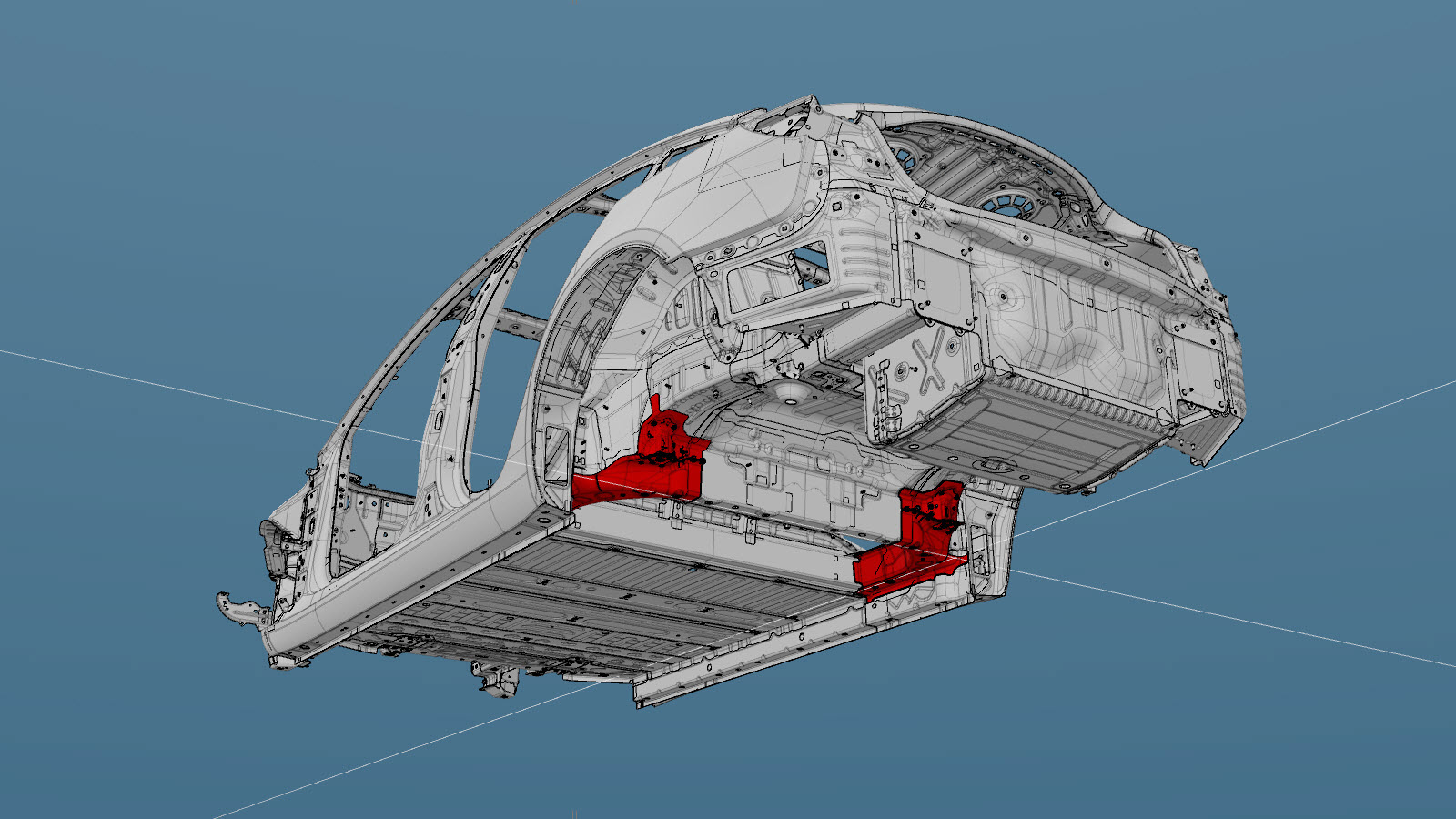
Rear Subframe Mount
 Correction code:
10101814202
10101814302
NOTE:
Unless explicitly stated in the procedure, the above
correction code includes all Collision Repair and Service
repair work required to perform this procedure, including
the linked Collision Repair procedures and linked Service
procedures. Do not stack Collision Repair correction
codes unless explicitly told to do so. Depending
on the damage to the vehicle, additional repairs may be
required.
Correction code:
10101814202
10101814302
NOTE:
Unless explicitly stated in the procedure, the above
correction code includes all Collision Repair and Service
repair work required to perform this procedure, including
the linked Collision Repair procedures and linked Service
procedures. Do not stack Collision Repair correction
codes unless explicitly told to do so. Depending
on the damage to the vehicle, additional repairs may be
required.
Repair Information
- Review all collision repair general practices and safety documentation and wear the appropriate PPE (Personal Protective Equipment) before beginning this procedure.
- Properly mount the vehicle on a frame bench when performing this procedure.
Parts List
| Quantity | Description | Image / Notes |
|---|---|---|
| 1 | ASY, RR SUBFRAME MNT (Rear Subframe Mount) | |
| 27 | High Strength Structural Rivet, 6.5 mm | |
| 16 | Structural Bulb Rivet, 6.5 mm |
When ordering parts, refer to the Parts Catalog and enter the VIN of the vehicle being repaired to find the correct parts (and the part numbers) for the vehicle. Alternatively, use the search function in the Parts Catalog to find a specific part for the vehicle.
Repair Procedure
- Remove the Fascia Assembly - Rear (Remove and Install).
- Remove the Valance - Front Fascia (Remove and Replace).
- Remove the Panel - Aero Shield - Front (Remove and Replace).
- Remove the HV Battery (RWD) (Remove and Replace).
- Remove the Brake Line Assembly - Side Sill (Remove and Replace).
- Remove the Subframe Assembly - Rear (Remove and Replace).
- Remove the Assembly - Brake Lines - Rear - RH (Remove and Replace).
- Remove the Retractor - Seatbelt - 2nd Row - Outboard (Single Side) (Remove and Replace).
- Remove the Carpet - Rear (Remove and Replace).
- Remove the Cable Kit - Charge Port (3 Phase) (EU) (Remove and Replace).
- Remove the Busbar - Charge Port to HV Battery (China) (Remove and Replace).
- Remove the Skid Plate - HV Battery - Rear (Remove and Replace).
-
Cut the floor panel at the
indicated locations, and bend it back to create a flap large enough to allow
removal of the Rear Subframe Mount and to uncover spot welds to be removed
when removing the original Rear Subframe Mount from the vehicle.
Cut Line
Reference Line/Point
- A = 20 mm.
-
Remove
the outer portion of the original component.
or Factory Spot Welds
or Drill through factory spot weldsNoteWhen drilling out spot welds, use a drill bit that creates a hole correctly sized for the fastener that will replace the spot weld. -
Remove
the inner portion of the original component.
or Factory Spot Welds
or Drill through factory spot weldsNoteWhen drilling out spot welds, use a drill bit that creates a hole correctly sized for the fastener that will replace the spot weld. -
Prepare for installation.
NoteA red X indicates a location where a factory-installed fastener is not being replaced. Secure this location using structural adhesive only.
or Steel Plug Welds
or Installation Spot Welds
or High Strength Structural Rivets, 6.5 mm- B = 8 mm.
- F = 43 mm.
- G = 25 mm.
- H = 7 mm.
- I = 2 mm.
- J = 30 mm.
- K = 20 mm.
or Structural Bulb Rivets, 6.5 mm- C = 70 mm.
- D = 30 mm.
- E = 6 mm.
WarningFor the Structural Bulb Rivets circled in red: Restore the floor panel section that was bent in the removal step to its original location before installing these rivets. -
Apply structural adhesive to the mating surfaces on the vehicle and the new component or components.
NoteApply a small amount of structural adhesive to the upper side of the floor panel flap created earlier.
- Bend the floor panel flap to its original location.
- Install the new component or components.
-
Perform resistance spot
welding.
or Installation Spot WeldsWarningFailure to follow all welding safety precautions, including the use of personal protective equipment, could result in serious injury or property damage. Only technicians who have completed Tesla’s approved welding training are authorized to weld structural components on Tesla vehicles.CAUTIONDo not weld on a Tesla vehicle before performing the Vehicle Electrical Isolation Procedure (refer to the vehicle-specific Service Manual for more information on the Vehicle Electrical Isolation Procedure). Welding on a Tesla vehicle with an energized high or low voltage system might damage vehicle components.
-
Perform GMA welding.
or Steel Plug WeldsWarningFailure to follow all welding safety precautions, including the use of personal protective equipment, could result in serious injury or property damage. Only technicians who have completed Tesla’s approved welding training are authorized to weld structural components on Tesla vehicles.WarningTo maintain vehicle crash integrity, use only approved welding wire and an approved GMA welder to perform GMA welding on Tesla vehicles. Refer to Approved Gas Metal Arc (GMA) Welders and Welding Wire for information on approved GMA welders and welding wire.CAUTIONDo not weld on a Tesla vehicle before performing the Vehicle Electrical Isolation Procedure (refer to the vehicle-specific Service Manual for more information on the Vehicle Electrical Isolation Procedure). Welding on a Tesla vehicle with an energized high or low voltage system might damage vehicle components.NoteBefore GMA welding, a test weld using material of the same gauge and type should be performed to make sure that the welding equipment settings produce a satisfactory joint.
- Perform any necessary post-repair operations.
- Install the Skid Plate - HV Battery - Rear (Remove and Replace).
- Install the Busbar - Charge Port to HV Battery (China) (Remove and Replace).
- Install the Cable Kit - Charge Port (3 Phase) (EU) (Remove and Replace).
- Install the Carpet - Rear (Remove and Replace).
- Install the Retractor - Seatbelt - 2nd Row - Outboard (Single Side) (Remove and Replace).
- Install the Assembly - Brake Lines - Rear - RH (Remove and Replace).
- Install the Subframe Assembly - Rear (Remove and Replace).
- Install the Brake Line Assembly - Side Sill (Remove and Replace).
- Install the HV Battery (RWD) (Remove and Replace).
- Install the Panel - Aero Shield - Front (Remove and Replace).
- Install the Valance - Front Fascia (Remove and Replace).
- Install the Fascia Assembly - Rear (Remove and Install).