Rear Wheel Arch (Complete)
 Correction code:
10101907102
10101907202
NOTE:
Unless explicitly stated in the procedure, the above
correction code includes all Collision Repair and Service
repair work required to perform this procedure, including
the linked Collision Repair procedures and linked Service
procedures. Do not stack Collision Repair correction
codes unless explicitly told to do so. Depending
on the damage to the vehicle, additional repairs may be
required.
Correction code:
10101907102
10101907202
NOTE:
Unless explicitly stated in the procedure, the above
correction code includes all Collision Repair and Service
repair work required to perform this procedure, including
the linked Collision Repair procedures and linked Service
procedures. Do not stack Collision Repair correction
codes unless explicitly told to do so. Depending
on the damage to the vehicle, additional repairs may be
required.
Repair Information
- Review all collision repair general practices and safety documentation and wear the appropriate PPE (Personal Protective Equipment) before beginning this procedure.
- This procedure can be completed without using a frame bench.
- This component may be replaced in a single repair as a single complete component, using the ASY, RR WHEELHOUSE OTR (Rear Wheel Arch) service part and the instructions in the Repair Procedure section of this document. Alternatively, any individual section or any combination of sections of the Rear Wheel Arch can be replaced so long as the guidelines from the Sectioning Guidelines are followed.
Parts List
| Quantity | Description | Image / Notes |
|---|---|---|
| 1 | ASY, RR WHEELHOUSE OTR (Rear Wheel Arch) | |
| 2 | Rivet, 4.8 mm | |
| 4 | Structural Bulb Rivet, 6.5 mm | |
| 6 | Countersunk Rivet, 4.8 mm Long | |
| 2 | BUTYL FOIL PATCH 300X150x2MM | Tesla part number 1004969-00-A. |
When ordering parts, refer to the Parts Catalog and enter the VIN of the vehicle being repaired to find the correct parts (and the part numbers) for the vehicle. Alternatively, use the search function in the Parts Catalog to find a specific part for the vehicle.
Sectioning Guidelines
- It is allowable to cut through a clearance hole or a non functional hole (exterior trim hole), as described below.
- Do not cut within 25 mm. of the center of a bolt hole or stud.
- Sections do not require fasteners at butt or overlap joints unless specifically indicated.
- Gaps between panels of overlaid and butt joints should be as small as possible to maximize joint strength.
- Seal all open seams after structural adhesive has cured.
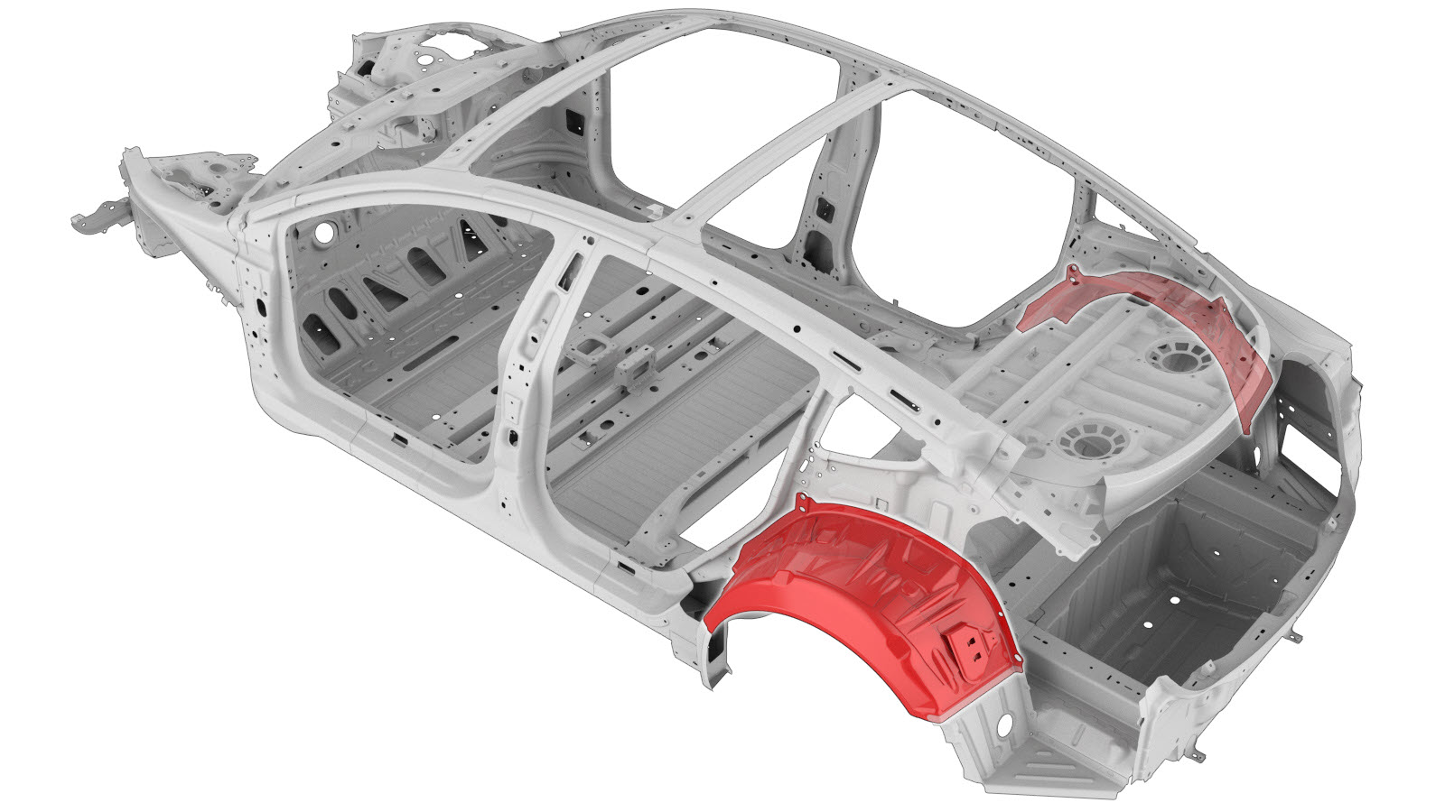
The image below shows the Rear Wheel Arch (complete). The colored areas indicate if sectioning is allowed. Compare the damaged area of the vehicle's Wheelhouse Outer to the image below, then use the repair criteria corresponding to the color of the highlighted area to find the criteria to use to determine if the damaged area of the component can be sectioned.
| Rear Wheel Arch (Complete) | Allowed Sectioning |
|---|---|
Refer to the section description below for measurements and important information.
| Section Description | Joint Description |
|---|---|
|
|
Repair Procedure
- Remove the Wheel Arch Liner - Rear - LH (Remove and Replace).
- Remove the Bracket - Rear - Center (Remove and Replace).
- Remove the Bracket - Rear Wing - LH (Remove and Replace).
- Remove the Charge Port (NACS) (Remove and Replace).
- Remove the Front Carpet - Rear Trunk (Remove and Replace).
- Remove the Trim - Side - Trunk - LH (Remove and Replace).
- Remove the Striker - Door - LH (Remove and Replace).
- Remove the Cover - Rocker Panel - Lower - LH (Remove and Replace).
-
Remove the C–Pillar Reinforcement.
-
Remove the Rear Wheelhouse Reinforcement.
-
Remove the original component.
NoteA red X indicates a location where a factory-installed fastener is not being replaced. Secure this location using structural adhesive only.
or Factory Spot Welds
or Factory SPRs
or Drill through factory spot weldsNoteWhen drilling out spot welds, use a drill bit that creates a hole correctly sized for the fastener that will replace the spot weld. -
Prepare for installation.
or Countersunk Rivets, 4.8 mm LongNoteA red X indicates a location where a factory-installed fastener is not being replaced. Secure this location using structural adhesive only.
- Apply structural adhesive to the mating surfaces on the vehicle and the new component or components.
- Install the new component or components.
-
Install the Rear Wheelhouse Reinforcement.
-
Install the C–Pillar Reinforcement.
- Perform any necessary post-repair operations.
- Install the Cover - Rocker Panel - Lower - LH (Remove and Replace).
- Install the Striker - Door - LH (Remove and Replace).
- Install the Trim - Side - Trunk - LH (Remove and Replace).
- Install the Front Carpet - Rear Trunk (Remove and Replace).
- Install the Charge Port (NACS) (Remove and Replace).
- Install the Bracket - Rear Wing - LH (Remove and Replace).
- Install the Bracket - Rear - Center (Remove and Replace).
- Install the Wheel Arch Liner - Rear - LH (Remove and Replace).