Front Shock Tower Support (Front)
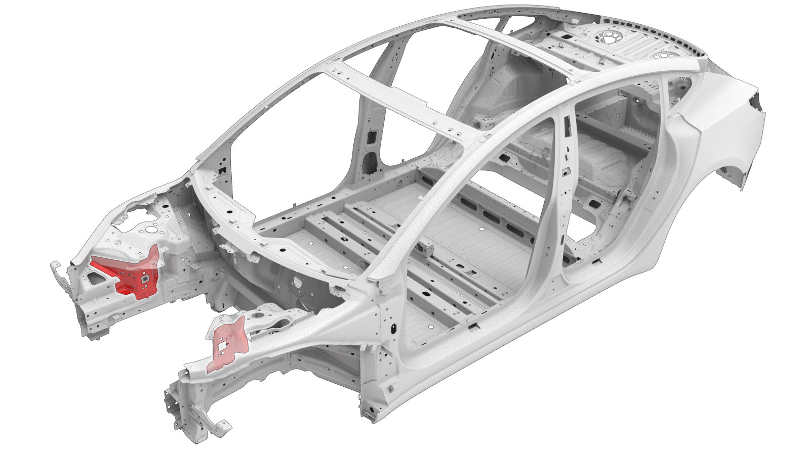 Correction code:
10101015402
10101002902
NOTE:
Unless explicitly stated in the procedure, the above
correction code includes all Collision Repair and Service
repair work required to perform this procedure, including
the linked Collision Repair procedures and linked Service
procedures. Do not stack Collision Repair correction
codes unless explicitly told to do so. Depending
on the damage to the vehicle, additional repairs may be
required.
Correction code:
10101015402
10101002902
NOTE:
Unless explicitly stated in the procedure, the above
correction code includes all Collision Repair and Service
repair work required to perform this procedure, including
the linked Collision Repair procedures and linked Service
procedures. Do not stack Collision Repair correction
codes unless explicitly told to do so. Depending
on the damage to the vehicle, additional repairs may be
required.
Repair Information
- Review all collision repair general practices and safety documentation and wear the appropriate PPE (Personal Protective Equipment) before beginning this procedure.
- Properly mount the vehicle on a frame bench when performing this procedure.
Parts List
| Quantity | Description | Image / Notes |
|---|---|---|
| 1 | ASY, SHOCK TWR SUP FR (Front Shock Tower Support – Front) | |
| 23 | High Strength Structural Rivet, 6.5 mm | |
| 2 | Structural Bulb Rivet, 6.5 mm | |
| 3 | Bolt , HF, M8-1.25X16 | Tesla part number 1011818-00-A. |
| 3 | Nut , HF, M8-1.25 | Tesla part number 1006628-01-A. |
When ordering parts, refer to the Parts Catalog and enter the VIN of the vehicle being repaired to find the correct parts (and the part numbers) for the vehicle. Alternatively, use the search function in the Parts Catalog to find a specific part for the vehicle.
Repair Procedure
- Remove the Fender Assembly - Front - LH (Remove and Install).
- Remove the Carrier - Bumper - Front (Remove and Replace).
- Remove the Cooling Fan Module (Remove and Replace).
- Remove the Radiator (Remove and Replace).
- Remove the Panel - Aero Shield - Rear (Remove and Replace).
- Remove the Knuckle - Front - LH (Remove and Replace).
- Remove the Damper - Front - LH (Dual Motor) (Remove and Replace).
- Remove the Mount - Front Upper Control Arm - LH (Remove and Replace).
- Remove the Brake Hydraulic Control Unit (Remove and Replace).
- Remove the Assembly - Brake Booster and Master Cylinder (LHD) (Remove and Replace).
- Remove the Assembly - Brake Lines - Front (Remove and Install).
-
Remove the original component.
or Factory Spot Welds
-
Prepare for installation.
NoteA red X indicates a location where a factory-installed fastener is not being replaced. Secure this location using structural adhesive only.or High Strength Structural Rivets, 6.5 mm
- A = 16 mm.
- B = 9 mm.
or Structural Bulb Rivets, 6.5 mm
or Bolts
- Apply structural adhesive to the mating surfaces on the vehicle and the new component or components.
-
Install the new component or components.
Torque the bolts to 22 Nm.
- Perform any necessary post-repair operations.
- Install the Assembly - Brake Lines - Front (Remove and Install).
- Install the Assembly - Brake Booster and Master Cylinder (LHD) (Remove and Replace).
- Install the Brake Hydraulic Control Unit (Remove and Replace).
- Install the Mount - Front Upper Control Arm - LH (Remove and Replace).
- Install the Damper - Front - LH (Dual Motor) (Remove and Replace).
- Install the Knuckle - Front - LH (Remove and Replace).
- Install the Panel - Aero Shield - Rear (Remove and Replace).
- Install the Radiator (Remove and Replace).
- Install the Cooling Fan Module (Remove and Replace).
- Install the Carrier - Bumper - Front (Remove and Replace).
- Install the Fender Assembly - Front - LH (Remove and Install).