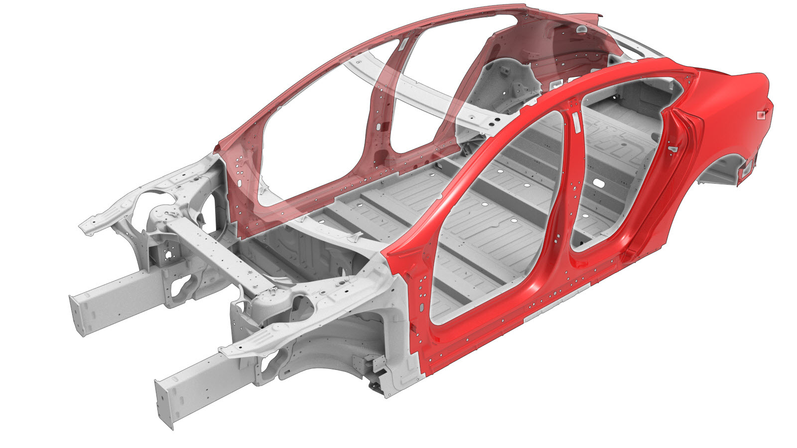
Body Side Outer (Generation 2 Rear Node and Generation 1 B-Pillar)
 Correction code:
10100142702
10100142802
NOTE:
Unless explicitly stated in the procedure, the above
correction code includes all Collision Repair and Service
repair work required to perform this procedure, including
the linked Collision Repair procedures and linked Service
procedures. Do not stack Collision Repair correction
codes unless explicitly told to do so. Depending
on the damage to the vehicle, additional repairs may be
required.
Correction code:
10100142702
10100142802
NOTE:
Unless explicitly stated in the procedure, the above
correction code includes all Collision Repair and Service
repair work required to perform this procedure, including
the linked Collision Repair procedures and linked Service
procedures. Do not stack Collision Repair correction
codes unless explicitly told to do so. Depending
on the damage to the vehicle, additional repairs may be
required.
Repair Information
- Any individual section or any combination of sections of the Body Side Outer can be replaced so long as the referenced cut lines from the Body Side Outer Section Descriptions portion of this document are used.
- Review all collision repair general practices and safety documentation and wear the appropriate PPE (Personal Protective Equipment) before beginning this procedure.
- This procedure can be completed without using a frame bench.
Verify This is the Correct Procedure
- Generation 2 Rear
Node: This Rear Node was installed on vehicles built on or after
November 5, 2014.
Refer to Model S Rear Node Versions for information on identifying the generation of the Rear Node in the vehicle.
- Generation 1 B-Pillar: This B-Pillar was installed on Model S vehicles built
before October 12, 2016.
Refer to Model S B-Pillar Generation Identification for information on identifying the generation of the B-Pillar in the vehicle.
| Rear Node | B-Pillar | Correct Procedure |
|---|---|---|
| Generation 1 | Generation 1 | Body Side Outer (Generation 1 Rear Node and Generation 1 B-Pillar) |
| Generation 2 | Generation 1 | Body Side Outer (Generation 2 Rear Node and Generation 1 B-Pillar) (this procedure) |
| Generation 2 | Generation 2 | Body Side Outer (Generation 2 Rear Node and Generation 2 B-Pillar) |
Using this Document
- Body Side Outer Section Descriptions provide information on
where and how to section the Body Side Outer Assembly (or subassemblies)
as necessary to replace damaged areas of the Body Side Outer panel, or
to gain access to underlying parts of the vehicle structure. Use the
section descriptions to determine where to successfully section the Body
Side Outer Assembly as needed for the repair being performed.NoteSections of the Body Side Outer Assembly can be replaced individually or in any combination of sections so long as the referenced cut locations identified in this document are used.NoteMeasurements from bolt hole locations are from the center of the referenced holes unless stated differently in the section description.
- The Removal and Replacement portions of this document contain the information necessary to replace the entire Body Side Outer Assembly. If replacing sections of the Body Side Outer Assembly (not the entire Body Side Outer), use the relevant portions of each step to determine which parts and fasteners are needed and the necessary steps to complete the repair.
Parts List
| Quantity | Description | Image / Notes |
|---|---|---|
| 1 | ASSY - BODY SIDE OTR COMP (Body Side Outer Complete) |
Note A pre-cut
subassembly may be used if sectioning the Body Side Outer.
See Body Side Outer Section Descriptions for more information. |
| 1 | High Strength Structural Rivet, 6.5 mm | |
| 11 | Structural Bulb Rivet, 6.5 mm | |
| 10 | Structural Rivet, 6.5 mm Medium | |
| 4 | Countersunk Rivet, 4.8 mm Long | |
| 2 | Countersunk Rivet, 4.8 mm Short | |
| 4 | High Strength Structural Flange Rivet, 6.5 mm | |
| 8 | Structural Flange Rivet | |
| 35 | Flow Form Rivet S08 | |
| 19 | Flow Form Rivet S18 | |
| 32 | Flow Form Rivet S28 | |
| 23 | Flow Form Rivet S38 | |
| 104 | Flow Form Rivet S48 | |
| 13 | Flow Form Rivet S58 | |
| 2 | Flow Form Rivet S68 | |
| 2 | Bolt, Panhead Flange , M8 x 1.25 x 16 PAN FLANGE HEAD | Tesla part number 1008833-01-A. |
| 4 | Bolt, hex-head | Tesla part number 1057210-00-A. |
| 6 | Nut , M8-1.25,HF,Steel | Tesla part number 1006628-01-A. |
| 1 | BUTYL PATCH 300X150X2 | Tesla part number 1004969-00-A. |
When ordering parts, refer to the Parts Catalog and enter the VIN of the vehicle being repaired to find the correct parts (and the part numbers) for the vehicle. Alternatively, use the search function in the Parts Catalog to find a specific part for the vehicle.
Body Side Outer Section Descriptions
| Body Side Outer Service Assemblies and Sections | |
|---|---|
The Body Side Outer Complete is a single component, and can be
replaced as a single repair. Alternatively, instead of replacing
the complete Body Side Outer, areas of the Body Side Outer can
be replaced using:
Warning When cutting sections, do not cut bolt
holes. Note Install a
backing plate behind each butt joint if there is sufficient
space and use structural adhesive to fill any gaps behind
panels and underlying components. |
|
| Assembly or Subasembly | Sections |
| ASSY - BODY SIDE OTR COMP | |
| ASSY - PNL-BODY SIDE OTR | |
| ASSY - BODY SIDE OTR A-PILLAR | |
| ASSY - BODY SIDE OTR B-PILLAR | |
| ASSY - BODY SIDE OTR C-PILLAR | |
| Body Side Outer Section | |
|---|---|
|
Hinge Pillar Cut Line Reference Line/Point
Note The cut can be made within 60 mm. of the specified
location to allow sectioning of the Door Ring Outer. GMA Weld or Aluminum Plug Welds |
|
|
A-Pillar Cut Line Reference Line/Point
Note The cut can be made within 369 mm. of the specified
location to allow sectioning of the Door Ring Outer. GMA Weld or Aluminum Plug Welds |
|
|
Front Sill Cut Line Reference Line/Point
Note The cut can be made within 270 mm. of the specified
location to allow sectioning of the Door Ring Outer. GMA Weld or Aluminum Plug Welds |
|
|
B-Pillar Cut Line Reference Line/Point
Note The cut can be made within 76 mm. of the specified
location. GMA Weld or Aluminum Plug Welds Warning Do not weld a panel where it directly
contacts underlying structural components. The heat affect
zone from welding can weaken the strength of underlying
structural components. Use structural adhesive to fill any
gaps behind panels and underlying components. |
|
|
Rear Roof Rail Cut Line Reference Line/Point
Note The cut can be made up to 200 mm. forward or up to 280 mm.
to the rear of the specified location to allow sectioning of
the Door Ring Outer. GMA Weld or Aluminum Plug Welds |
|
|
Rear Sill Cut Line Reference Line/Point
Note The cut can be made within 70 mm. of the specified
location to allow sectioning of the Door Ring Outer. GMA Weld or Aluminum Plug Welds |
|
|
Dogleg Cut Line Reference Line/Point
Note The Quarter Outer Complete procedure
must be performed before this section can be replaced. Note The cut can be made within 70 mm. of the specified
location. GMA Weld or Aluminum Plug Welds |
|
|
Rear Quarter Cut Line Reference Line/Point
GMA Weld or Aluminum Plug Welds |
|
Repair Procedure
-
Remove the component that
covers the Front Header Assembly:
Depending on the vehicle build date, the component that covers the Front Header Assembly may be any of the following:
- Roof Assembly (refer to procedure)
- Roof Glass (refer to procedure)
- Panoramic Roof Assembly frame (refer to procedure)
-
Remove the original component.
or Factory Spot Welds
or Factory SPRs
or Drill through factory spot weldsNoteWhen drilling out spot welds, use a drill bit that creates a hole correctly sized for the fastener that will replace the spot weld.or Factory Structural Rivets
Factory Pin and Collar
-
Prepare for installation.
NoteA red X indicates a location where a factory-installed fastener is not being replaced. Secure this location using structural adhesive only.
or High Strength Structural Rivets, 6.5 mm
or Structural Bulb Rivets, 6.5 mm- A = 10 mm.
- B = 57 mm.
or Countersunk Rivets, 4.8 mm Short
or Countersunk Rivets, 4.8 mm Long- C = 14 mm.
- D = 51 mm.
or Structural Rivets, 6.5 mm Medium
or High Strength Structural Flange Rivet, 6.5 mm
- Apply structural adhesive to the mating surfaces on the vehicle and the new component or components.
-
Install the new component or components.
Torque the bolts to 25 Nm.
-
If performing a section
repair only:
Perform GMA welding on the butt joints.
GMA Weld
or Aluminum Plug Welds
WarningDo not weld a panel where it directly contacts an underlying structural component. The heat from welding might weaken the strength of the structural component.WarningFailure to follow all welding safety precautions, including the use of personal protective equipment, could result in serious injury or property damage. Only technicians who have completed Tesla’s approved welding training are authorized to weld structural components on Tesla vehicles.WarningTo maintain vehicle crash integrity, use only approved welding wire and an approved GMA welder to perform GMA welding on Tesla vehicles. Refer to Approved Gas Metal Arc (GMA) Welders and Welding Wire for information on approved GMA welders and welding wire.CAUTIONDo not weld on a Tesla vehicle before performing the Vehicle Electrical Isolation Procedure (refer to the vehicle-specific Service Manual for more information on the Vehicle Electrical Isolation Procedure). Welding on a Tesla vehicle with an energized high or low voltage system might damage vehicle components.NoteBefore GMA welding, a test weld using material of the same gauge and type should be performed to make sure that the welding equipment settings produce a satisfactory joint. -
If a camera is not to be installed, install a butyl patch.
Trim the butyl patch to fit within the gasket of the B-Pillar applique.NoteThe following measurements are approximate.
- E = 60 mm.
- F = 125 mm.
- G = 80 mm.
-
Install the component that
was removed to provide access to the Front Header Assembly:
- Roof Assembly (refer to procedure)
- Roof Glass (refer to procedure)
- Panoramic Roof Assembly frame (refer to procedure)
-
Enlarge the existing holes in the the B-Pillar and the B-Pillar Seal
Carriers to 10 mm.
-
Install the B-Pillar Seal Carriers.
- Perform any necessary post-repair operations.