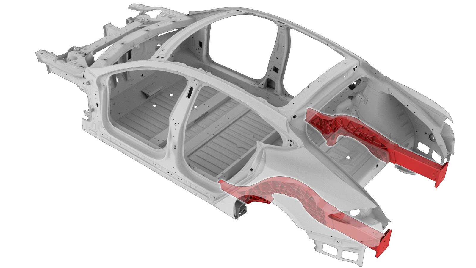
Rear Node (Complete) (Vehicles Built After November 5, 2014)
 Correction code:
10101816502
10101816702
NOTE:
Unless explicitly stated in the procedure, the above
correction code includes all Collision Repair and Service
repair work required to perform this procedure, including
the linked Collision Repair procedures and linked Service
procedures. Do not stack Collision Repair correction
codes unless explicitly told to do so. Depending
on the damage to the vehicle, additional repairs may be
required.
Correction code:
10101816502
10101816702
NOTE:
Unless explicitly stated in the procedure, the above
correction code includes all Collision Repair and Service
repair work required to perform this procedure, including
the linked Collision Repair procedures and linked Service
procedures. Do not stack Collision Repair correction
codes unless explicitly told to do so. Depending
on the damage to the vehicle, additional repairs may be
required.
Repair Information
- Depending on the damage to this component, it may be possible to repair this component. Refer to Cast Rear Node Repair Guidelines (Vehicles Built After October 5, 2014) for more information.
- This repair procedure is only for vehicles built after November 5, 2014. There is no Rear Node replacement for vehicles built before November 5, 2014. See Model S Rear Node Versions to determine which version of Rear Node is in the vehicle being repaired.
- Review all collision repair general practices and safety documentation and wear the appropriate PPE (Personal Protective Equipment) before beginning this procedure.
- Properly mount the vehicle on a frame bench when performing this procedure.
Parts List
| Quantity | Description | Image / Notes |
|---|---|---|
| 1 | MODEL S, ASY-MEMBER RAIL RR (Rear Node – Complete) | |
| 33 | ||
| 2 | Bolt, hex-head , BOLT HF M8X50 PC109 MAT | Tesla part number 1046838-00-A. |
| 4 | Bolt, hex-head , SCR,M8-1.25X20,HF,MAT PNT,STL,ZNC,PATCH | Tesla part number 1007580-00-A. |
| 2 | SPAC NUT,M8X2.8-3.5,STL[10] | Tesla part number 1071915-00-A. |
When ordering parts, refer to the Parts Catalog and enter the VIN of the vehicle being repaired to find the correct parts (and the part numbers) for the vehicle. Alternatively, use the search function in the Parts Catalog to find a specific part for the vehicle.
Repair Procedure
-
Remove the Rear Panel Assembly.
-
Remove the Rear Trunk Floor Assembly.
-
Remove the Rear Trunk Floor Extension (Vehicles Built Through November 5, 2014).
-
Remove the Wheelhouse Extension.
-
Remove the Rear Node Outer Reinforcement.
-
Remove the Rear Node Upper Reinforcement (Middle).
-
Remove the Rear Seat Floor Panel Section.
-
Remove the original component.
GMA Weld
-
Prepare for installation.
or High Strength Structural Rivets, 6.5 mm
- A = 144 mm.
- B = 9 mm.
- C = 58 mm.
- D = 25 mm.
- E = 53 mm.
- F = 11 mm.
- G = 22 mm.
- H = 19 mm.
- I = 59 mm.
- J = 36 mm.
- K = 66 mm.
- L = 34 mm.
- M = 56 mm.
- N = 35 mm.
- O = 71 mm.
- P = 12 mm.
- Q = 7 mm.
- R = 10 mm.
- S = 23 mm.
- T = 45 mm.
- U = 65 mm.
- V = 14 mm.
- W = 80 mm.
GMA Weld
- Position the new Rear Node component and clamp it in place.
-
Drill 8 mm. holes for
hex-head bolts through the factory bosses (circled in red) in the new Rear
Node component.
- Remove the new Rear Node component.
-
Enlarge the 8 mm. holes created in a previous step to 11.5 mm.
-
Apply structural adhesive to the inboard side of the SPAC nuts, then clamp
them in place.
- Apply structural adhesive to the mating surfaces on the vehicle and the new component or components.
-
Install the new component or components.
Torque the Hex-head bolts as follows:
- BOLT HF M8X50 PC109 MAT bolts part number 1007580-00-A: 25 Nm.
- SCR,M8-1.25X20,HF,MAT PNT,STL,ZNC,PATCH bolts part number 1046838-00-A: 30 Nm.
-
Perform GMA welding.
GMA WeldWarningFailure to follow all welding safety precautions, including the use of personal protective equipment, could result in serious injury or property damage. Only technicians who have completed Tesla’s approved welding training are authorized to weld structural components on Tesla vehicles.WarningTo maintain vehicle crash integrity, use only approved welding wire and an approved GMA welder to perform GMA welding on Tesla vehicles. Refer to Approved Gas Metal Arc (GMA) Welders and Welding Wire for information on approved GMA welders and welding wire.CAUTIONDo not weld on a Tesla vehicle before performing the Vehicle Electrical Isolation Procedure (refer to the vehicle-specific Service Manual for more information on the Vehicle Electrical Isolation Procedure). Welding on a Tesla vehicle with an energized high or low voltage system might damage vehicle components.NoteBefore GMA welding, a test weld using material of the same gauge and type should be performed to make sure that the welding equipment settings produce a satisfactory joint.
-
Install the Rear Seat Floor Panel Section.
-
Install the Rear Node Upper Reinforcement (Middle).
-
Install the fasteners as indicated.
or High Strength Structural Rivets, 6.5 mm
- F = 11 mm.
- X = 100 mm.
- Y = 50 mm.
-
Install the Rear Node Outer Reinforcement.
-
Install the Wheelhouse Extension.
-
Install the Rear Trunk Floor Extension (Vehicles Built Through November 5, 2014).
-
Install the Rear Trunk Floor Assembly.
-
Install the Rear Panel Assembly.
- Perform any necessary post-repair operations.