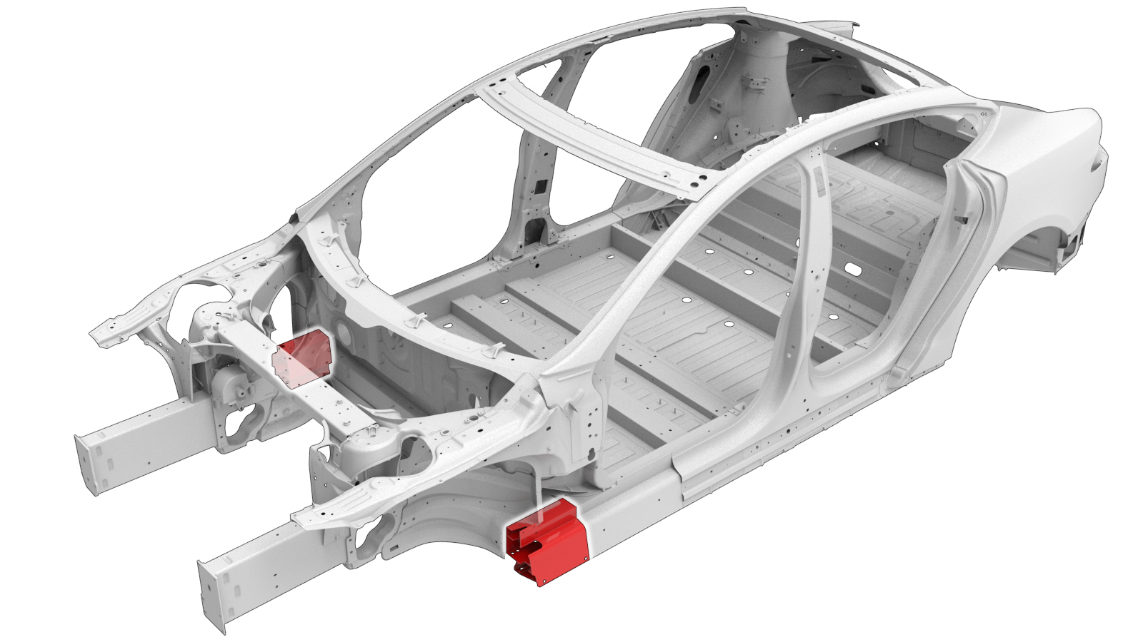
Sill (Front Section)
 Correction code:
10102902002
10102903102
NOTE:
Unless explicitly stated in the procedure, the above
correction code includes all Collision Repair and Service
repair work required to perform this procedure, including
the linked Collision Repair procedures and linked Service
procedures. Do not stack Collision Repair correction
codes unless explicitly told to do so. Depending
on the damage to the vehicle, additional repairs may be
required.
Correction code:
10102902002
10102903102
NOTE:
Unless explicitly stated in the procedure, the above
correction code includes all Collision Repair and Service
repair work required to perform this procedure, including
the linked Collision Repair procedures and linked Service
procedures. Do not stack Collision Repair correction
codes unless explicitly told to do so. Depending
on the damage to the vehicle, additional repairs may be
required.
Repair Information
- Depending on the damage to this component, it may be possible to repair this component. Refer to Sill Repair Guidelines for more information.
- Review all collision repair general practices and safety documentation and wear the appropriate PPE (Personal Protective Equipment) before beginning this procedure.
- This procedure can be completed without using a frame bench.
Parts List
| Quantity | Description | Image / Notes |
|---|---|---|
| 1 | FRONT SILL SECTION KIT (Sill - Front Section Kit) | |
| Front Sill Complete Section | ||
| Upper Cell Lower Backing Plate | ||
| Upper Cell Upper Backing Plate | ||
| Lower Cell Backing Plate | ||
| Middle Cell Backing Plate | ||
| 16 | Structural Countersunk Rivet, 6.5 mm | |
| 11 | Structural Bulb Rivet, 6.5 mm | |
| 3 | Structural Rivet, 6.5 mm Medium | |
| 3 | Pop Rivets, 4.8 mm | |
| 9 | Rivnut, M6 - 1.00x3 | |
| 2 | Rivnut, M8 - 1.25x3 |
When ordering parts, refer to the Parts Catalog and enter the VIN of the vehicle being repaired to find the correct parts (and the part numbers) for the vehicle. Alternatively, use the search function in the Parts Catalog to find a specific part for the vehicle.
Repair Procedure
-
Remove the necessary portion
of the Hinge Pillar Assembly.
-
Remove the Front Frame Rail Outer Extension Reinforcement.
-
Remove the Torque Box Plate.
-
Remove the Sill Nut Strip.
or Factory Structural Rivets
-
Remove the Sill Insert.
or Factory Structural Rivets
Rivnut
-
Remove the original component.
Cut Line
Reference Line/Point
- A = 228 mm.
- B = 214 mm.
Rivnut
GMA WeldNoteAn additional weld may be present in some vehicles remove the weld as necessary for the section repair. -
Test fit the new component and trim to fit.
- C = 190 mm.
-
Create and install a backing plate on the replacement
component.
or Structural Bulb Rivets, 6.5 mmNoteTrim the supplied backing plate to 90 mm.
-
Create and install backing plates
on the vehicle.
or Structural Bulb Rivets, 6.5 mmNoteTrim the supplied backing plates to 90 mm.
-
Prepare for installation.
- Drill out any existing holes that are obstructed by backing plates.
- Apply structural adhesive to the mating surfaces on the vehicle and the new component or components.
- Install the new component or components.
-
Perform GMA welding.
NoteGrind down the welds on the lower flange, Torque Box to Sill joint, and the inboard vertical Sill until they are flush with the surrounding panels.
GMA Weld
WarningFailure to follow all welding safety precautions, including the use of personal protective equipment, could result in serious injury or property damage. Only technicians who have completed Tesla’s approved welding training are authorized to weld structural components on Tesla vehicles.WarningTo maintain vehicle crash integrity, use only approved welding wire and an approved GMA welder to perform GMA welding on Tesla vehicles. Refer to Approved Gas Metal Arc (GMA) Welders and Welding Wire for information on approved GMA welders and welding wire.CAUTIONDo not weld on a Tesla vehicle before performing the Vehicle Electrical Isolation Procedure (refer to the vehicle-specific Service Manual for more information on the Vehicle Electrical Isolation Procedure). Welding on a Tesla vehicle with an energized high or low voltage system might damage vehicle components.NoteBefore GMA welding, a test weld using material of the same gauge and type should be performed to make sure that the welding equipment settings produce a satisfactory joint. -
Install the Sill Insert.
-
Install the rivnuts in the
Sill Insert and Sill Front Section.
Rivnut
-
Install the Sill Nut Strip.
-
Install the Torque Box Plate.
-
Install the Front Frame Rail Outer Extension Reinforcement.
-
Install the Wheelhouse Extension.
-
Install portion of the Hinge Pillar Assembly that
was removed to expose the component being replaced.
- Perform any necessary post-repair operations.