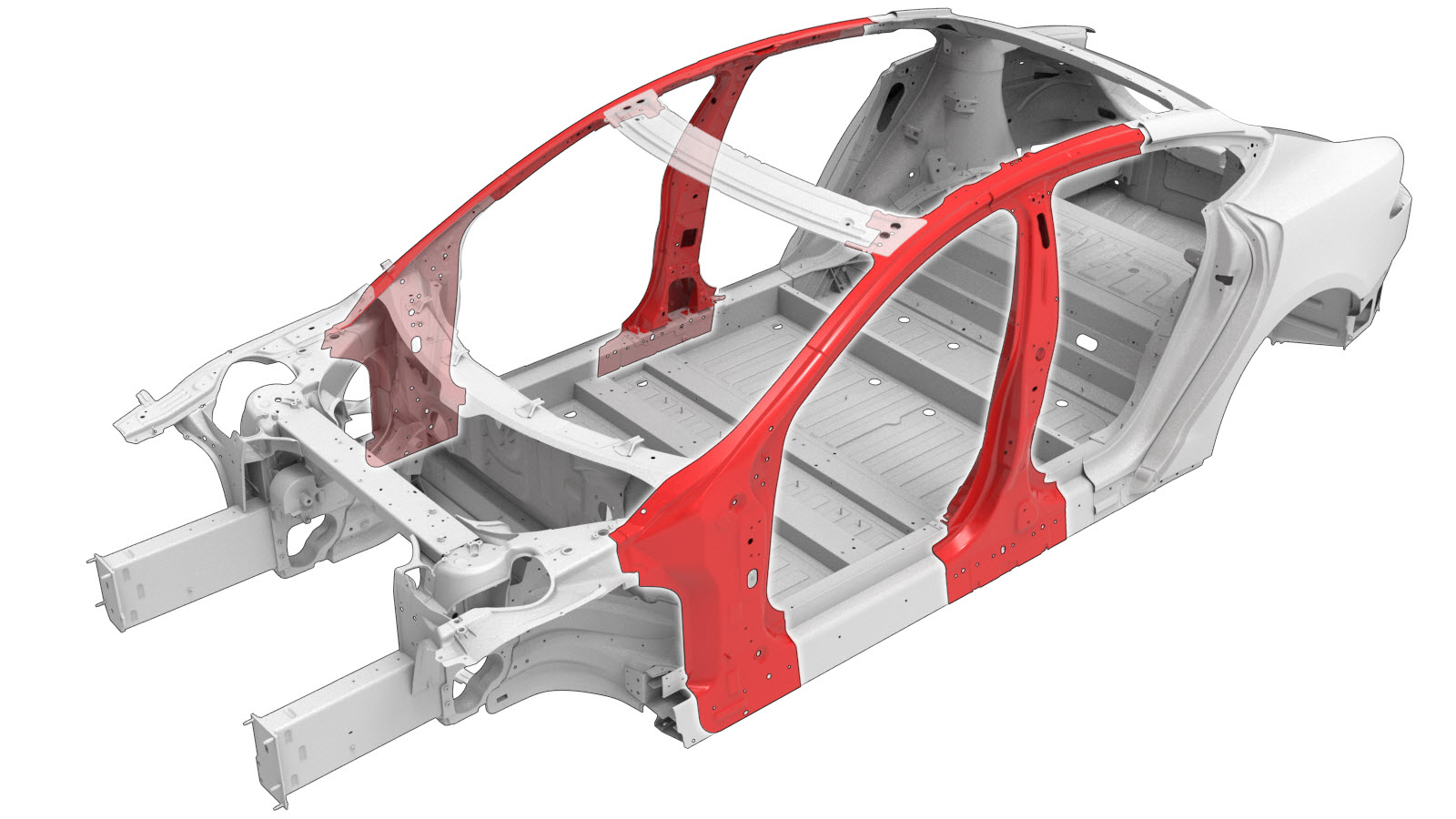
A–Pillar and B–Pillar Complete Assembly (Vehicles Built After October 11, 2016)
 Correction code:
10100106902
10100122702
NOTE:
Unless explicitly stated in the procedure, the above
correction code includes all Collision Repair and Service
repair work required to perform this procedure, including
the linked Collision Repair procedures and linked Service
procedures. Do not stack Collision Repair correction
codes unless explicitly told to do so. Depending
on the damage to the vehicle, additional repairs may be
required.
Correction code:
10100106902
10100122702
NOTE:
Unless explicitly stated in the procedure, the above
correction code includes all Collision Repair and Service
repair work required to perform this procedure, including
the linked Collision Repair procedures and linked Service
procedures. Do not stack Collision Repair correction
codes unless explicitly told to do so. Depending
on the damage to the vehicle, additional repairs may be
required.
Repair Information
- Review all collision repair general practices and safety documentation and wear the appropriate PPE (Personal Protective Equipment) before beginning this procedure.
- Properly mount the vehicle on a frame bench when performing this procedure.
Parts List
| Quantity | Description | Image / Notes |
|---|---|---|
| 1 | ASSY - A / B PILLAR COMP (A–Pillar and B–Pillar Complete Assembly) | |
| 10 | Structural Rivet, 6.5 mm Medium | |
| 8 | Flow Form Rivet S58 | |
| 2 | Flow Form Rivet S68 | |
| 5 | SPR, 5x6 H4 | |
| 2 | SPR, 5x8 | |
| 2 | SPR, 5x9 | |
| 2 | Bolt, hex-head , BLT,HFLG,M10X22,[10.9]-MM-11 | Tesla part number 1012961-00-A. |
| 4 | Nut , NUT HF M8 PC10 | Tesla part number 1046842-00-A. |
When ordering parts, refer to the Parts Catalog and enter the VIN of the vehicle being repaired to find the correct parts (and the part numbers) for the vehicle. Alternatively, use the search function in the Parts Catalog to find a specific part for the vehicle.
Repair Procedure
-
Remove the Shotgun Upper Assembly.
-
Remove the Shotgun Outer Assembly.
-
Remove the necessary portion
of the Body Side Outer to expose
the underlying component being replaced.
-
Remove the Hinge Pillar Assembly.
-
Remove the original component.
or Factory Spot Welds
or Factory SPRs
or Factory Structural Rivets
Cut LineWarningWhen removing the necessary portion of the Roof Rail Outer to expose the underlying joints, do not damage the Roof Rail Inner when cutting the Roof Rail Outer.Reference Line/Point
- A = 160 mm.
GMA Weld
-
Cut the new ASSY - A / B
PILLAR COMP as indicated below to make the new component.
Cut LineWarningDo not damage the Roof Rail Inner when cutting the Roof Rail Outer.
Reference Line/Point
- B = 163 mm.
-
Install the backing plate on the Roof Rack
Outer.
or Aluminum Plug Welds
-
Prepare for installation.
or Structural Flange Rivets, 6.5 mmor Structural Rivets, 6.5 mm Medium
- C = 34 mm.
- D = 30 mm.
or SPRs, 5x6 H4NoteUse the following Tesla SPR die to install this SPR: FM 090 2120.or SPRs, 5x8NoteUse the following Tesla SPR die to install this SPR: FM 090 2120.or SPRs, 5x9NoteUse the following Tesla SPR die to install this SPR: FM 090 2120.GMA Weld
or Aluminum Plug Welds
- Apply structural adhesive to the mating surfaces on the vehicle and the new component or components.
-
Install the new component or components.
Torque the nuts and bolts to 25 Nm.
-
Perform GMA welding.
GMA WeldWarningFailure to follow all welding safety precautions, including the use of personal protective equipment, could result in serious injury or property damage. Only technicians who have completed Tesla’s approved welding training are authorized to weld structural components on Tesla vehicles.WarningTo maintain vehicle crash integrity, use only approved welding wire and an approved GMA welder to perform GMA welding on Tesla vehicles. Refer to Approved Gas Metal Arc (GMA) Welders and Welding Wire for information on approved GMA welders and welding wire.CAUTIONDo not weld on a Tesla vehicle before performing the Vehicle Electrical Isolation Procedure (refer to the vehicle-specific Service Manual for more information on the Vehicle Electrical Isolation Procedure). Welding on a Tesla vehicle with an energized high or low voltage system might damage vehicle components.NoteBefore GMA welding, a test weld using material of the same gauge and type should be performed to make sure that the welding equipment settings produce a satisfactory joint.
-
Install the portion of the
Body Side Outer that was
removed to expose the component being replaced.
-
Install the Shotgun Outer Assembly.
-
Install the Shotgun Upper Assembly.
- Perform any necessary post-repair operations.