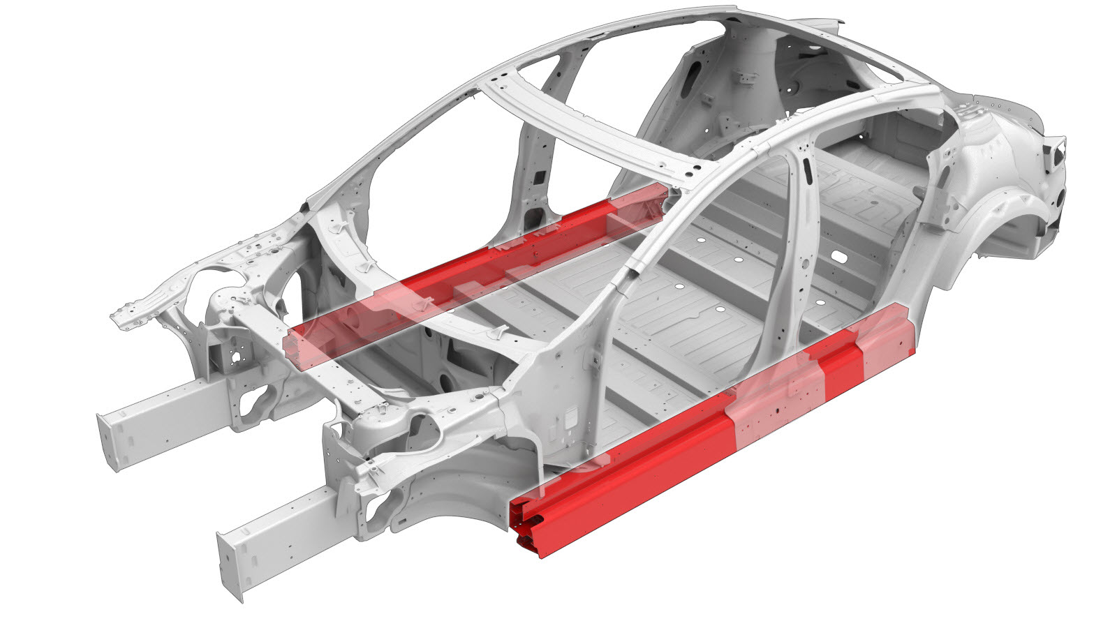
Sill (Complete)
 Correction code:
10100301002
10100301102
NOTE:
Unless explicitly stated in the procedure, the above
correction code includes all Collision Repair and Service
repair work required to perform this procedure, including
the linked Collision Repair procedures and linked Service
procedures. Do not stack Collision Repair correction
codes unless explicitly told to do so. Depending
on the damage to the vehicle, additional repairs may be
required.
Correction code:
10100301002
10100301102
NOTE:
Unless explicitly stated in the procedure, the above
correction code includes all Collision Repair and Service
repair work required to perform this procedure, including
the linked Collision Repair procedures and linked Service
procedures. Do not stack Collision Repair correction
codes unless explicitly told to do so. Depending
on the damage to the vehicle, additional repairs may be
required.
Repair Information
- This repair procedure is only for vehicles built after November 5, 2014 (vehicles built with second generation Rear Nodes). For more information about rear node versions, and how to determine if the vehicle has a first or second generation rear node, see Model S Rear Node Versions.
- Depending on the damage to this component, it may be possible to repair this component. Refer to Sill Repair Guidelines for more information.
- Review all collision repair general practices and safety documentation and wear the appropriate PPE (Personal Protective Equipment) before beginning this procedure.
- Properly mount the vehicle on a frame bench when performing this procedure.
Parts List
| Quantity | Description | Image / Notes |
|---|---|---|
| 1 | ASY SIDE SILL (Sill – Complete) | |
| 1 | ASY, GUSSET RAMP |
Note This
part is only for vehicles built after April 10, 2016. |
| 37 | High Strength Structural Rivet, 6.5 mm | |
| 7 | Structural Bulb Rivet, 6.5 mm | |
| 2 | Structural Flange Rivet | |
| 12 | Structural Rivet, 6.5 mm Medium | |
| 2 | SPAC NUT,M8X2.8-3.5,STL[10] | Tesla part number 1071915-00-A. |
| 2 | Bolt, hex-head HF M8X50 PC109 MAT | Tesla part number 1046838-00-A. |
| 4 | Nut ,M8-1.25,HF,STEEL[10],ZNAL,BLACK | Tesla part number 1006628-01-A. Note This
part is only for vehicles built after April 10, 2016. |
When ordering parts, refer to the Parts Catalog and enter the VIN of the vehicle being repaired to find the correct parts (and the part numbers) for the vehicle. Alternatively, use the search function in the Parts Catalog to find a specific part for the vehicle.
Repair Procedure
-
Remove the necessary portion
of the Body Side Outer to expose
the underlying component being replaced.
-
Remove the necessary portion of the Hinge Pillar Assembly.
-
Remove the Wheelhouse Extension.
-
Remove the Front Frame Rail Outer Extension Reinforcement.
-
Remove the Torque Box Plate.
-
For vehicles built
through April 10, 2016 only: Detach the bottom of the B–Pillar from
the Sill.
GMA Weld
-
For vehicles built after
April 10, 2016 only: Detach the bottom of the B–Pillar from the
Gusset Ramp.
-
Remove the original component.
or Factory Spot Welds
or Factory SPRs
or Drill through factory spot weldsNoteWhen drilling out spot welds, use a drill bit that creates a hole correctly sized for the fastener that will replace the spot weld.or Factory Structural Rivets
GMA Weld
-
Prepare for installation.
Cut Line
Reference Line/Point
- A = 48 mm.
- B = 9 mm.
- C = 22 mm.
- D = 12 mm.
or High Strength Structural Rivets, 6.5 mm- E = 58 mm.
- F = 32 mm.
- G = 39 mm.
- H = 144 mm.
- I = 14 mm.
- J = 30 mm.
- K = 25 mm.
- L = 20 mm.
- M = 11 mm.
- N = 50 mm.
- O = 34 mm.
- P = 45 mm.
- Q = 65 mm.
- R = 55 mm.
- S = 80 mm.
- T = 90 mm.
- U = 6 mm.
- V = 44 mm.
- W = 166 mm.
- X = 8 mm.
- Y = 62 mm.
- Z = 142 mm.
- AA = 160 mm.
- BB = 185 mm.
- CC = 230 mm.
- DD = 56 mm.
- EE = 70 mm.
- FF = 49 mm.
- GG = 47 mm.
or Structural Bulb Rivets, 6.5 mm
or Structural Flange Rivets, 6.5 mm
or Structural Rivets, 6.5 mm Medium
A GMA Weld
- Temporarily position the Sill.
-
Drill 8 mm. holes through the Rear Node in the locations circled in red.
- Remove the Sill.
-
Enlarge the 8 mm. holes in the Sill to 11.5 mm.
-
Apply adhesive to the back of the SPAC nuts, position them in the Sill, and clamp them in place.
- Apply structural adhesive to the mating surfaces on the vehicle and the new component or components.
-
Install the new component or components.
Install and torque the bolts to 25 Nm.
-
For vehicles built after
April 10, 2016 only: Install the Gusset Ramp on the Sill.
Refer to the installation instructions in the B-Pillar Gusset Ramp repair procedure.
-
For vehicles built after
April 10, 2016 only: Secure the bottom of the B–Pillar to the Gusset
Ramp.
Nut
Torque the nuts to 25 Nm.
-
For vehicles built
through April 10, 2016 only: Secure the bottom of the B–Pillar to
the Sill.
GMA Weld
-
Perform GMA welding.
or Aluminum Plug Welds
GMA Weld
WarningFailure to follow all welding safety precautions, including the use of personal protective equipment, could result in serious injury or property damage. Only technicians who have completed Tesla’s approved welding training are authorized to weld structural components on Tesla vehicles.WarningTo maintain vehicle crash integrity, use only approved welding wire and an approved GMA welder to perform GMA welding on Tesla vehicles. Refer to Approved Gas Metal Arc (GMA) Welders and Welding Wire for information on approved GMA welders and welding wire.CAUTIONDo not weld on a Tesla vehicle before performing the Vehicle Electrical Isolation Procedure (refer to the vehicle-specific Service Manual for more information on the Vehicle Electrical Isolation Procedure). Welding on a Tesla vehicle with an energized high or low voltage system might damage vehicle components.NoteBefore GMA welding, a test weld using material of the same gauge and type should be performed to make sure that the welding equipment settings produce a satisfactory joint. -
Install the Torque Box Plate.
-
Install the Front Frame Rail Outer Extension Reinforcement.
-
Install the fasteners as indicated.
or High Strength Structural Rivets, 6.5 mm
- D = 12 mm.
- P = 45 mm.
- Q = 65 mm.
- S = 80 mm.
- T = 90 mm.
- U = 6 mm.
- V = 44 mm.
- W = 166 mm.
- X = 8 mm.
- Y = 62 mm.
- Z = 142 mm.
- AA = 160 mm.
- BB = 185 mm.
- CC = 230 mm.
- DD = 56 mm.
- EE = 70 mm.
- FF = 49 mm.
- GG = 47 mm.
-
Install the Wheelhouse Extension.
-
Install the portion of the Hinge Pillar Assembly that was removed to expose the component being replaced.
-
Install the portion of the
Body Side Outer that was
removed to expose the component being replaced.
- Perform any necessary post-repair operations.