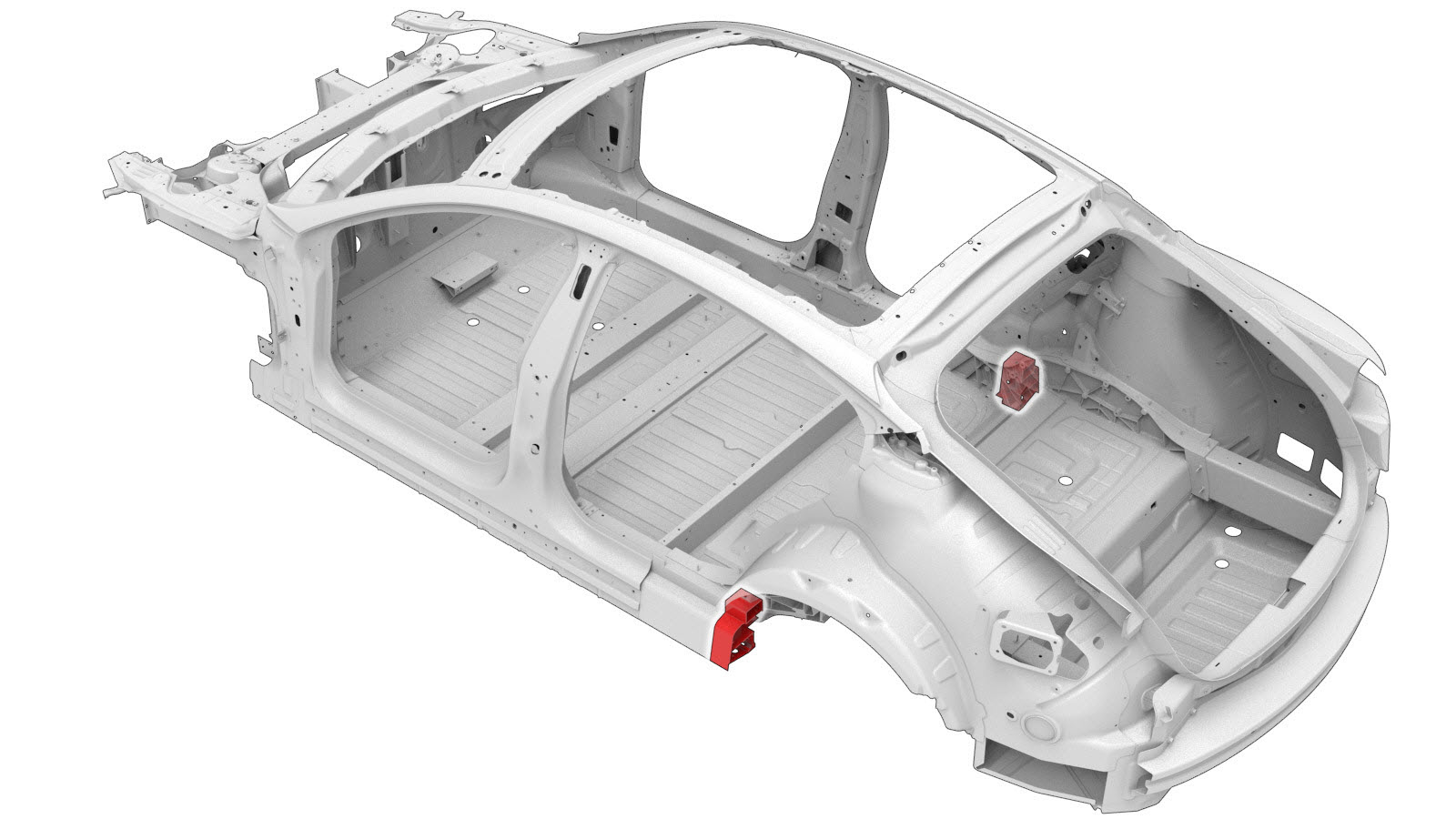
Sill (Rear Section)
 Correction code:
10102901602
10102901902
NOTE:
Unless explicitly stated in the procedure, the above
correction code includes all Collision Repair and Service
repair work required to perform this procedure, including
the linked Collision Repair procedures and linked Service
procedures. Do not stack Collision Repair correction
codes unless explicitly told to do so. Depending
on the damage to the vehicle, additional repairs may be
required.
Correction code:
10102901602
10102901902
NOTE:
Unless explicitly stated in the procedure, the above
correction code includes all Collision Repair and Service
repair work required to perform this procedure, including
the linked Collision Repair procedures and linked Service
procedures. Do not stack Collision Repair correction
codes unless explicitly told to do so. Depending
on the damage to the vehicle, additional repairs may be
required.
Repair Information
- If the damaged area of the Side Sill is not within 70 mm. of the rear edge of the Side Sill (measured from the bottom of the Side Sill), discontinue this procedure and perform the Sill (Complete) procedure.
- Depending on the damage to this component, it may be possible to repair this component. Refer to Sill Repair Guidelines for more information.
- Review all collision repair general practices and safety documentation and wear the appropriate PPE (Personal Protective Equipment) before beginning this procedure.
- This procedure can be completed without using a frame bench.
Parts List
| Quantity | Description | Image / Notes |
|---|---|---|
| 1 | ASY SIDE SILL (Sill – Complete) | |
| 1 | Upper Cell Lower Backing Plate |
Tesla part number 1074848-00-A. |
| 1 | Upper Cell Upper Backing Plate |
Tesla part number 1074920-00-A. |
| 1 | Middle Cell Backing Plate |
Tesla part number 1074924-00-A. |
| 1 | Lower Cell Backing Plate |
Tesla part number 1074922-00-A. |
| 16 | Structural Countersunk Rivet, 6.5 mm | |
| 19 | High Strength Structural Rivet, 6.5 mm | |
| 3 | Pop Rivets | |
| 1 | Rivnut, NUT RVT RND THN M8-1.25X3.0 ZNNI | Tesla part number 2007223. |
| 3 | Bolt, hex-head , BOLT PF M8X20 PC 98 ADH MAT | Tesla part number 1014747-00-B. |
| 2 | Bolt, hex-head , BOLT HF M8X50 PC109 MAT | Tesla part number 1046838-00-A. |
| 2 | SPAC NUT ,M8x3.8-5,STL[10],ZNI | Tesla part number 1060097-00-B. |
When ordering parts, refer to the Parts Catalog and enter the VIN of the vehicle being repaired to find the correct parts (and the part numbers) for the vehicle. Alternatively, use the search function in the Parts Catalog to find a specific part for the vehicle.
Repair Procedure
-
Remove the Rear Node Upper Reinforcement (Front).
NoteDo not remove the Rear Node Upper Reinforcement (Middle) or the Rear Node Upper Reinforcement (Rear).
-
Remove the C–Pillar Reinforcement.
-
Remove the Wheelhouse Extension.
-
Remove the Sill Nut
Strip.
or Factory Structural Rivets
-
Remove the original component.
Cut Line
Reference Line/Point
- A = 80 mm.
- B = 70 mm.
GMA WeldNoteAn additional weld may be present in some vehicles. Remove the weld as necessary for the section repair. -
Cut the new Side Sill as
indicated below to make the new component.
Cut Line
Reference Line/Point
- C = 80 mm.
- D = 70 mm.
-
Grind down the rib highlighted in red to provide a flat space to mount a
backing plate.
-
Remove the rivnut from the new component.
-
Cut a section of the new Side Sill as indicated below to make backing
plates for the new component.
Cut Line
Reference Line/Point
- E = 160 mm.
- F = 85 mm.
-
Trim the purchased cell backing plates to length.
- Upper Cell Lower Back Plate: Trim to 160 mm.
- Upper Cell Upper Backing Plate: Trim to 160 mm.
- Middle Cell Backing Plate: Trim to 160 mm.
- Lower Cell Backing Plate: Trim to 150 mm.
-
Grind the inboard surface of
the middle cell flat to provide an area to mount a backing plate.
- G = 80 mm.
-
Position the inboard backing plates for the upper cell and the middle cell,
and clamp them in place.
-
Drill an 11 mm. hole in the
upper cell upper backing plate for a Rivnut in the indicated location.
-
Drill 8 mm. holes for
hex-head bolts through the factory bosses (circled in red) in the Rear Node
and through the Side Sill backing plates.
- Remove the Side Sill backing plates.
- Enlarge the 8 mm. holes created in a previous step to 11.5 mm.
-
Apply adhesive to the back
of the SPAC nuts, position them in the backing plates, and clamp them in
place.
-
Install the Rivnut in the Upper Cell Upper Backing Plate.
Rivnut
-
Install backing plates on the vehicle.
-
Prepare for installation.
- Drill out any existing holes that are obstructed by backing plates.
- Apply structural adhesive to the mating surfaces on the vehicle and the new component or components.
-
Install the new component or components.
Torque all bolts to 25 Nm.
-
Perform GMA welding.
NoteGrind down the welds on the lower flange and the inboard vertical side of the Sill until they are flush with the surrounding panels.
GMA Weld
WarningFailure to follow all welding safety precautions, including the use of personal protective equipment, could result in serious injury or property damage. Only technicians who have completed Tesla’s approved welding training are authorized to weld structural components on Tesla vehicles.WarningTo maintain vehicle crash integrity, use only approved welding wire and an approved GMA welder to perform GMA welding on Tesla vehicles. Refer to Approved Gas Metal Arc (GMA) Welders and Welding Wire for information on approved GMA welders and welding wire.CAUTIONDo not weld on a Tesla vehicle before performing the Vehicle Electrical Isolation Procedure (refer to the vehicle-specific Service Manual for more information on the Vehicle Electrical Isolation Procedure). Welding on a Tesla vehicle with an energized high or low voltage system might damage vehicle components.NoteBefore GMA welding, a test weld using material of the same gauge and type should be performed to make sure that the welding equipment settings produce a satisfactory joint. -
Install the Sill Nut
Strip.
or Pop Rivets
-
Install the Rear Node Upper Reinforcement (Front).
-
Install the C–Pillar Reinforcement.
-
Install the Wheelhouse Extension.
- Perform any necessary post-repair operations.