Door Ring Outer
 Correction code:
10100136402
10100136502
NOTE:
Unless explicitly stated in the procedure, the above
correction code includes all Collision Repair work required
to perform this procedure, including the linked Collision
Repair procedures. Do not stack Collision Repair
correction codes unless explicitly told to do
so. Add any associated mechanical procedures
needed to perform this procedure.
Correction code:
10100136402
10100136502
NOTE:
Unless explicitly stated in the procedure, the above
correction code includes all Collision Repair work required
to perform this procedure, including the linked Collision
Repair procedures. Do not stack Collision Repair
correction codes unless explicitly told to do
so. Add any associated mechanical procedures
needed to perform this procedure.
Repair Information
- Any individual section or any combination of sections of the Door Ring Outer can be replaced so long as the referenced cut lines from the Door Ring Outer Section Descriptions portion of this document are used.
- Review all collision repair general practices and safety documentation and wear the appropriate PPE (Personal Protective Equipment) before beginning this procedure.
- Properly mount the vehicle on a frame bench when performing this procedure.
Parts List
| Quantity | Description | Image / Notes |
|---|---|---|
| 1 Note For section repairs only:
Some section repairs require a second part. Refer to the Door Ring Outer Section Descriptions to determine if the planned section
repair requires an additional part. |
ASSEMBLY - DOOR RING OUTER (Door Ring Outer) |
|
| 2 | Structural Bulb Rivet, 6.5 mm | |
| 29 | High Strength Structural Rivet, 6.5 mm | |
| 22 | Flow Form Rivet S28 | |
| 32 | Flow Form Rivet S38 | |
| 12 | Flow Form Rivet S48 | |
| 3 | Flow Form Rivet S58 |
When ordering parts, refer to the Parts Catalog and enter the VIN of the vehicle being repaired to find the correct parts (and the part numbers) for the vehicle. Alternatively, use the search function in the Parts Catalog to find a specific part for the vehicle.
Door Ring Outer Section Descriptions
| Door Ring Outer, Subassemblies, and Subassembly Sectioning | ||
|---|---|---|
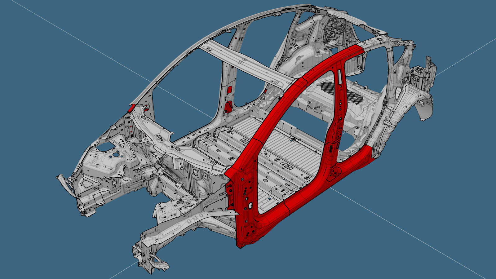
| The Door Ring Outer (shown below) is a single component, and can be replaced as a single repair: | ||
|
|
||
|
Alternatively, instead of replacing the complete Door Ring Outer, areas of the Door Ring Outer can be replaced using portions of the Door Ring Outer using the cut lines described in this document. |
||
|
|
||
| Door Ring Outer Sections |
| Door Ring Outer Section Descriptions | Parts Required | |
|---|---|---|
|
Sill Front Section Cut Line Reference Line/Point
Note
Create a reinforcement plate
60 mm wide, and install it as
indicated. |
|
|
|
Hinge Pillar Section Cut Line Reference Line/Point
Note
Create a backing plate
80 mm wide, and install it as
indicated. Note The rivet circled in red is
installed after the Body Side Outer component has been installed. |
|
Structural Bulb Rivet, 6.5 mm – 7. or Installation Spot Welds Note Order an additional Door
Ring Outer when performing this section repair. |
|
A–Pillar Section Cut Line Reference Line/Point
Note
Create a backing plate
80 mm wide, and install it as
indicated. |
|
Structural Bulb Rivet, 6.5 mm – 8. Rivet, 4.8 mm – 2. |
|
B–Pillar Upper Section Cut Line Reference Line/Point
Note
Create a backing plate
80 mm wide, and install it as
indicated. |
|
Structural Bulb Rivet, 6.5 mm – 8. Rivet, 4.8 mm – 2. |
|
B–Pillar Lower Section Cut Line Reference Line/Point
Note
Create a backing plate
80 mm wide, and install it as
indicated. |
|
Structural Bulb Rivet, 6.5 mm – 4. Rivet, 4.8 mm – 8. Note Order an additional Door Ring
Outer when performing this section repair. |
|
Sill Rear Section Cut Line Reference Line/Point
Note
Create a reinforcement plate
60 mm wide, and install it as
indicated. |
|
Structural Bulb Rivet, 6.5 mm – 10. Note Order an additional Door Ring
Outer when performing this section repair. |
Repair Procedure
-
Remove the Shotgun Outer to expose the underlying component
being replaced.
NoteWhen performing a section repair: If repairing any section other than the A-Pillar section, do not remove the Shotgun Outer. When repairing the A-Pillar section, remove the Shotgun Outer.
-
Remove the necessary portion of the
Body Side Outer to expose the
underlying component being replaced.
- If replacing a section of the Door Ring Outer: Mark the Door Ring Outer at the section cut line locations described in the Door Ring Outer Section Descriptions.
-
Remove the original component.
- or Factory Spot Welds
-
Remove the original component.
- or Drill through factory spot welds
NoteWhen drilling out spot welds, use a drill bit that creates a hole correctly sized for the fastener that will replace the spot weld.- or Factory Spot Welds
-
Remove the original component.
- or Drill through factory spot welds
NoteWhen drilling out spot welds, use a drill bit that creates a hole correctly sized for the fastener that will replace the spot weld.- or Factory Spot Welds
-
Remove the original component.
- or Drill through factory spot welds
NoteWhen drilling out spot welds, use a drill bit that creates a hole correctly sized for the fastener that will replace the spot weld.- or Factory Spot Welds
-
Remove the original component.
- or Factory Spot Welds
-
Remove the original component.
- or Drill through factory spot welds
NoteWhen drilling out spot welds, use a drill bit that creates a hole correctly sized for the fastener that will replace the spot weld.- or Factory Spot Welds
- For section repairs only: Create backing plates or reinforcement plates as described in the Door Ring Outer Section Descriptions.
-
Prepare for installation.
- or Installation Spot Welds
NoteInstallation Spot Welds circled in red are to be spot welded over existing weld; all other Installation Spot Welds are installed offset 14 mm from the center point of the factory location. -
Prepare for installation.
- or Installation Spot Welds
NoteInstall all Installation Spot Welds offset 14 mm from the center point of the factory location. -
Prepare for installation.
- Reference Line/Point
- or High Strength Structural Rivets, 6.5 mm Q = 30 mm
- or Flow Form Rivets, S28
- or Flow Form Rivets, S38
-
Prepare for installation.
- or Installation Spot Welds
NoteInstall all Installation Spot Welds offset 14 mm from the center point of the factory location. -
Prepare for installation.
- or Installation Spot Welds
NoteInstall all Installation Spot Welds offset 14 mm from the center point of the factory location. -
Prepare for installation.
- or Installation Spot Welds
NoteInstall all Installation Spot Welds offset 14 mm from the center point of the factory location. -
Prepare for installation.
- or Installation Spot Welds
NoteInstall all Installation Spot Welds offset 14 mm from the center point of the factory location. -
Prepare for installation.
- or Installation Spot Welds
NoteInstall all Installation Spot Welds offset 14 mm from the center point of the factory location. - Apply structural adhesive to the mating surfaces on the vehicle and the new component or components.
- For section repairs only: Install backing plates or reinforcement plates as described in the Door Ring Outer Section Descriptions.
- Install the new component or components.
-
Perform resistance spot
welding.
- or Installation Spot Welds
WarningFailure to follow all welding safety precautions, including the use of personal protective equipment, could result in serious injury or property damage. Only technicians who have completed Tesla’s approved welding training are authorized to weld structural components on Tesla vehicles.CAUTIONDo not weld on a Tesla vehicle before performing the Vehicle Electrical Isolation Procedure (refer to the vehicle-specific Service Manual for more information on the Vehicle Electrical Isolation Procedure). Welding on a Tesla vehicle with an energized high or low voltage system might damage vehicle components. -
Install the portion of the Body Side Outer that was removed to
expose the component being replaced.
-
If it was removed, install the Shotgun Outer.
- Install the fasteners as indicated.
- Install the fasteners as indicated.
- Install the fasteners as indicated.
- Install the fasteners as indicated.
- Perform any necessary post-repair operations.