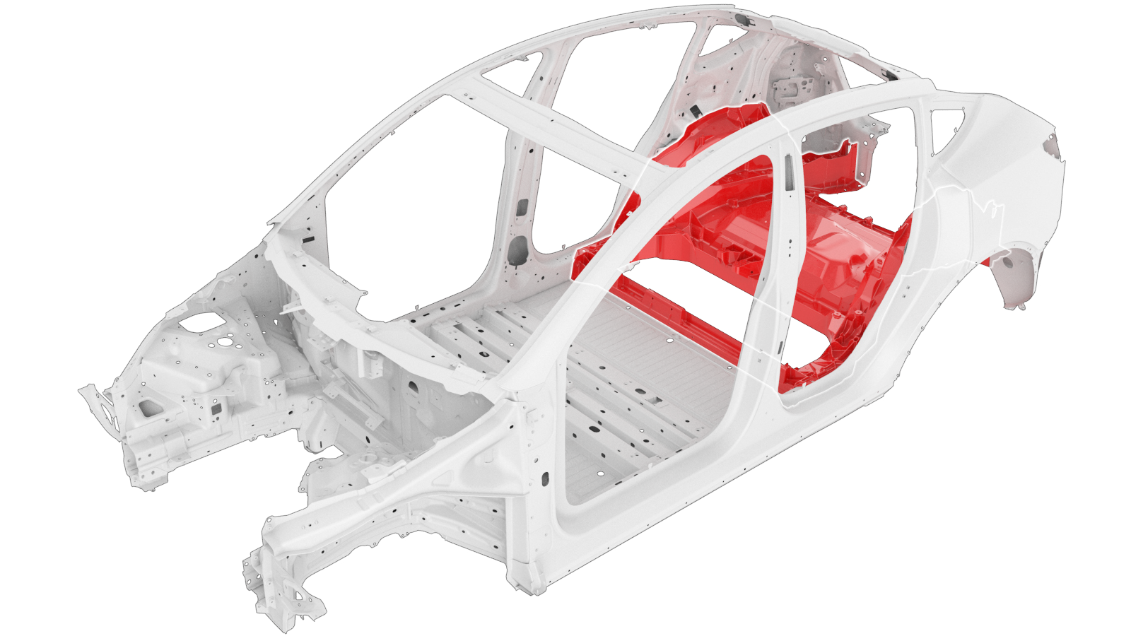
Cast Rub (Replace)
 Correction code:
10102101302
NOTE:
Unless explicitly stated in the procedure, the above
correction code includes all Collision Repair work required
to perform this procedure, including the linked Collision
Repair procedures. Do not stack Collision Repair
correction codes unless explicitly told to do
so. Add any associated mechanical procedures
needed to perform this procedure.
Correction code:
10102101302
NOTE:
Unless explicitly stated in the procedure, the above
correction code includes all Collision Repair work required
to perform this procedure, including the linked Collision
Repair procedures. Do not stack Collision Repair
correction codes unless explicitly told to do
so. Add any associated mechanical procedures
needed to perform this procedure.
Repair Information
- Depending on the damage to this component, it may be possible to repair this component. Refer to Cast Rear Under Body (1–Piece) Repair Guidelines for more information.
- Review all collision repair general practices and safety documentation and wear the appropriate PPE (Personal Protective Equipment) before beginning this procedure.
- Properly mount the vehicle on a frame bench when performing this procedure.
Parts List
| Quantity | Description | Image / Notes |
|---|---|---|
| 1 | ASSEMBLY - ONE PIECE CAST REAR UNDERBODY (Cast RUB - Rear Underbody) | |
| 1 | ASSEMBLY - EXTENSION REAR WHEEL HOUSE - LEFT HAND SERVICE E-COATED (Wheelhouse Front Extension - LH) | |
| 1 | ASSEMBLY - EXTENSION REAR WHEEL HOUSE - RIGHT HAND SERVICE E-COATED (Wheelhouse Front Extension - RH) | |
| 22 | High Strength Structural Rivet, 6.5 mm | |
| 12 | Rivet, 4.8 mm | |
| 10 | SEMS[FL],M8-1.25x37,[109],G1009,CM | Tesla part number 1629418-00. |
| 4 | Bolt , ,HF,M6x20,[88],ZNFL,MAT | Tesla part number 1120935-00. |
| 2 | NUT AND WASHER[FL] - HF - M8-1.25 - [10] - ZINC NICKEL | Tesla part number 1118837-00-A. |
| 2 | SEMS,[FL],HX,M8x23.5,[109],G1009,PTC | Tesla part number 1063260-00-C. |
When ordering parts, refer to the Parts Catalog and enter the VIN of the vehicle being repaired to find the correct parts (and the part numbers) for the vehicle. Alternatively, use the search function in the Parts Catalog to find a specific part for the vehicle.
Repair Procedure
-
Remove the LH and the RH Rear Panel Side Assembly.
-
Remove the LH and the RH Wing Bracket (Lower) components.
-
Create an access window in the
Wheelhouse Extension (Front).
- Reference Line/Point
- Cut Line A = 50 mm B = 130 mm C = 75 mm D = 15 mm
-
Cut the new Wheelhouse Extension
components to create LH and RH access window covers.
The finished cover should be approximately 32 mm wider and 10 mm taller than the access window (indicated by black dashed lines).NoteWhen positioned poperly, the cover overlaps the top, bottom, and inboard edges of the access window by 5 mm. The cover also overlaps the outboard edge of the access window by 27 mm.
- Reference Line/Point
- Cut LineE = 82 mmF = 140 mm
-
Remove the Rivnut from the new
component.
- Rivnut
-
Remove the original component.
- Rivnut
- or Bolts
-
Remove the original component.
- or Factory Spot Welds
- or Factory SPRs
-
Remove the original component.
- or Bolts
-
Remove the original component.
- or Factory SPRs
-
Remove the original component.
- or Bolts
- Prepare for installation.
-
Install the nut (Tesla part number
1118837-00-A) though the B Pillar hole where the seat belt retractor is located
(indicated in red).
-
Prepare for installation.
NoteA red X indicates a location where a factory-installed fastener is not being replaced.
- Reference Line/Point
- or High Strength Structural Rivets, 6.5 mm K = 17 mm
- or Bolts
-
Prepare for installation.
NoteA red X indicates a location where a factory-installed fastener is not being replaced.
-
Prepare for installation.
NoteA red X indicates a location where a factory-installed fastener is not being replaced.
- Reference Line/Point
- or Rivets, 4.8 mm G = 79 mm H = 24 mm I = 28 mm J = 26 mm
-
Prepare for installation.
NoteA red X indicates a location where a factory-installed fastener is not being replaced.NoteThe bolt in circled in red is replaced only if it was present on the original component.
-
Prepare for installation.
- or Bolts
- Apply structural adhesive to the mating surfaces on the vehicle and the new component or components.
-
Install the new component or components.
Torque bolts as follows:
- SEMS,[FL],HX,M8x23.5,[109],G1009,PTC bolt and washer (Tesla part number 1063260-00-C) installed horizontally in the Sill: 31 Nm.
- SEMS[FL],M8-1.25x37,[109],G1009,CM bolts (Tesla part number 1629418-00) installed horizontally in the Sill: 31 Nm.
- SEMS[FL],M8-1.25x37,[109],G1009,CM bolts (Tesla part number 1629418-00) installed vertically in the Sill: 35 Nm.
- HF,M6x20,[88],ZNFL,MAT bolts (Tesla part number 1120935-00) securing the Floor Crossmember to the Cast Rear Under Body: 28 Nm.
-
Install the LH and the RH Rear Rail End Plate components.
-
Install the LH and the RH Wing Bracket (Lower) components.
-
Install the LH and the RH Rear Panel Side Assembly.
-
Prepare to install the Access Window Covers.
NoteWhen positioned poperly, the cover overlaps the top, bottom, and inboard edges of the access window by 5 mm. The cover also overlaps the outboard edge of the access window by 27 mm.
- Apply structural adhesive to the mating surfaces on the vehicle and the Access Window Covers.
- Install the Access Window Covers.
- Perform any necessary post-repair operations.