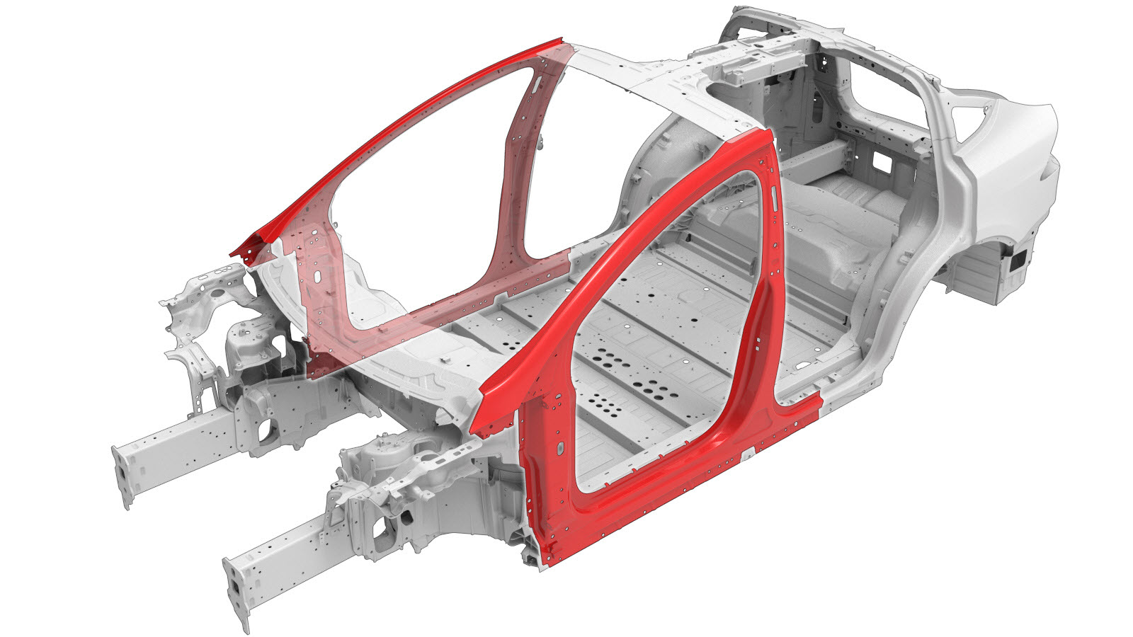
Body Side Outer
 Correction code:
10100130802
10100130902
NOTE:
Unless explicitly stated in the procedure, the above
correction code includes all Collision Repair and Service
repair work required to perform this procedure, including
the linked Collision Repair procedures and linked Service
procedures. Do not stack Collision Repair correction
codes unless explicitly told to do so. Depending
on the damage to the vehicle, additional repairs may be
required.
Correction code:
10100130802
10100130902
NOTE:
Unless explicitly stated in the procedure, the above
correction code includes all Collision Repair and Service
repair work required to perform this procedure, including
the linked Collision Repair procedures and linked Service
procedures. Do not stack Collision Repair correction
codes unless explicitly told to do so. Depending
on the damage to the vehicle, additional repairs may be
required.
Repair Information
- Review all collision repair general practices and safety documentation and wear the appropriate PPE (Personal Protective Equipment) before beginning this procedure.
- This procedure can be completed without using a frame bench.
Using this Document
- Body Side Outer Section Descriptions provide information on
where and how to section the Body Side Outer (or subassemblies) as
necessary to replace damaged areas of the Body Side Outer panel, or to
gain access to underlying parts of the vehicle structure. Use the
section descriptions to determine where to successfully section the Body
Side Outer as needed for the repair being performed.NoteSections of the Body Side Outer can be replaced individually or in any combination of sections so long as the referenced cut locations identified in this document are used.NoteMeasurements from bolt hole locations are from the center of the referenced holes unless stated differently in the section description.
- The Removal and Replacement portions of this document contain the information necessary to replace the entire Body Side Outer. If replacing sections of the Body Side Outer (not the entire Body Side Outer Assembly), use the relevant portions of each step to determine which parts and fasteners are needed and the steps required to complete the repair.
Parts List
| Quantity | Description | Image / Notes |
|---|---|---|
| If replacing the entire Body Side Outer: 1 | BODY SIDE OUTER COMPLETE (Body Side Outer – Complete) | |
| 3 | Structural Bulb Rivet, 6.5 mm | |
| 8 | High Strength Structural Rivet, 6.5 mm | |
| 3 | ||
| 1 | Countersunk Rivet, 4.8 mm Short | |
| 1 | Flow Form Rivet S08 | |
| 3 | Flow Form Rivet S18 | |
| 16 | Flow Form Rivet S28 | |
| 84 | Flow Form Rivet S38 | |
| 7 | Flow Form Rivet S48 | |
| 3 | Flow Form Rivet S58 | |
| 6 | Bolt | Tesla part number 1621820-00-A. |
| 3 | Bolt , M6x18 | Tesla part number 1006529-00-A. |
| 2 | Bolt , M10x80 | Tesla part number 1053943-00-A. |
| 1 | Bolt, Torx-head , M8x20 | Tesla part number 1014747-00-B. |
When ordering parts, refer to the Parts Catalog and enter the VIN of the vehicle being repaired to find the correct parts (and the part numbers) for the vehicle. Alternatively, use the search function in the Parts Catalog to find a specific part for the vehicle.
Body Side Outer Section Descriptions
| Body Side Outer, Subassemblies, and Subassembly Sectioning | |
|---|---|
| The BODY SIDE OUTER COMPLETE (shown below) is a single assembly, and can be replaced as a single repair: | Alternatively, instead of replacing the BODY SIDE OUTER COMPLETE, areas of the Body Side Outer Complete can be replaced using the cut lines described in this document. |
|
|
|
| Body Side Outer Section Descriptions | |
|---|---|
|
A–Pillar Section Cut Line Reference Line/Point
Warning Do not cut
bolt holes when cutting sections. Note The cut can be made within
350 mm of the specified cut line location to allow sectioning of the Body Side
Outer. Note Install a backing
plate behind each butt joint if there is sufficient space. Note The gap between the adjacent
panels of the butt joint for this section should be as small as possible to
maximize joint strength.
or Aluminum Plug Welds
Note For these plug welds, drill
a 9 mm hole in each of the indicated locations.
GMA Weld
Warning Do not weld
a panel where it directly contacts underlying structural components (the heat
affect zone from welding can weaken the strength of underlying structural
components). Use structural adhesive to fill gaps behind panels and underlying
components. |
|
|
Sill Section Cut Line Reference Line/Point
Warning Do not cut
bolt holes when cutting sections. Note The cut can be made within
235 mm of the specified cut line location to allow sectioning of the Body Side
Outer. Note Install a backing
plate behind each butt joint if there is sufficient space. Note The gap between the adjacent
panels of the butt joint for this section should be as small as possible to
maximize joint strength.
or Aluminum Plug Welds
Note For these plug welds, drill
a 9 mm hole in each of the indicated locations.
GMA Weld
Warning Do not weld
a panel where it directly contacts underlying structural components (the heat
affect zone from welding can weaken the strength of underlying structural
components). Use structural adhesive to fill gaps behind panels and underlying
components. |
|
|
B-Pillar Section Cut Line Reference Line/Point
Warning Do not cut
bolt holes when cutting sections. Note The cut can be made within 10
mm of the specified cut line location to allow sectioning of the Body Side
Outer. Note Install a backing
plate behind each butt joint if there is sufficient space. Note The gap between the adjacent
panels of the butt joint for this section should be as small as possible to
maximize joint strength.
or Aluminum Plug Welds
Note For these plug welds, drill
a 9 mm hole in each of the indicated locations.
GMA Weld
Warning Do not weld a panel where it directly contacts underlying
structural components (the heat affect zone from welding can weaken the
strength of underlying structural components). Use structural adhesive to fill
gaps behind panels and underlying components. |
|
Repair Procedure
- Remove the Carpet - Surround - Seat - 2nd Row - LH (Remove and Replace).
- Remove the Carpet - 1st Row (Remove and Replace).
- Remove the HV Battery (AWD) (Remove and Install).
- Remove the Headlight - LH (Remove and Replace).
- Remove the Hinge - Door - Front - Upper - LH (Remove and Replace).
- Remove the Hinge - Door - Front - Lower - LH (Remove and Replace).
- Remove the Carrier - Rocker Panel - LH (Remove and Replace).
- Remove the Striker - Door - Rear - LH (Remove and Replace).
- Remove the Bracket - Racetrack - B-Pillar - Lower - LH (Remove and Replace).
- Remove the Bracket - Racetrack - B-Pillar - Upper - LH (Remove and Replace).
- Remove the Bracket - Racetrack - Header - Front - LH (Remove and Replace).
- Remove the Seal - Body - Side - Rear - Primary - LH (Remove and Replace).
- Remove the Retractor - Seatbelt - 1st Row - LH (Remove and Replace).
- Remove the Striker - Door - Front - LH (Remove and Replace).
- Remove the Hood Assembly (Remove and Replace).
-
Remove the necessary portion of the A–Pillar Outer to expose the
underlying component being repaired.
-
Remove the original component.
-
Prepare for installation.
or High Strength Structural Rivets, 6.5 mmNoteA red X indicates a location where a factory-installed fastener is not being replaced. Secure this location using structural adhesive only.
- A = 94 mm.
- B = 11 mm.
- C = 35 mm.
- D = 9 mm.
or Structural Bulb Rivets, 6.5 mm
or Countersunk Rivets, 4.8 mm Short
or Countersunk Rivets, 4.8 mm Long
or Flow Form Rivets, S38- E = 48 mm.
- F = 12 mm.
- G = 8 mm.
- H = 9 mm.
- I = 9 mm.
- J = 8 mm.
- K = 9 mm.
- L = 9 mm.
- M = 13 mm.
- N = 9 mm.
- O = 5 mm.
- P = 9 mm.
or Flow Form Rivets, S58- Q = 15 mm.
- R = 9 mm.
or Bolts
- Apply structural adhesive to the mating surfaces on the vehicle and the new component or components.
-
If replacing a
section of the Body Side Outer only:
Perform GMA welding on the butt joints between sections.
GMA Weld
or Aluminum Plug Welds
NoteDo not weld a panel where it directly contacts a structural panel underneath. The heat from welding might weaken the strength of the underlying panel. Instead of welding, use structural adhesive to fill gaps between a panel and underlying panels.WarningFailure to follow all welding safety precautions, including the use of personal protective equipment, could result in serious injury or property damage. Only technicians who have completed Tesla’s approved welding training are authorized to weld structural components on Tesla vehicles.WarningTo maintain vehicle crash integrity, use only approved welding wire and an approved GMA welder to perform GMA welding on Tesla vehicles. Refer to Approved Gas Metal Arc (GMA) Welders and Welding Wire for information on approved GMA welders and welding wire.CAUTIONDo not weld on a Tesla vehicle before performing the Vehicle Electrical Isolation Procedure (refer to the vehicle-specific Service Manual for more information on the Vehicle Electrical Isolation Procedure). Welding on a Tesla vehicle with an energized high or low voltage system might damage vehicle components.NoteBefore GMA welding, a test weld using material of the same gauge and type should be performed to make sure that the welding equipment settings produce a satisfactory joint. -
Install the new component or components.
Torque the bolts as follows:
- Hex-head M8x27 bolts part number 1621820-00-A: 24 Nm.
- Hex-head M6x18 bolts part number 1006529-00-A: 12 Nm.
- Hex-head M8x27 bolts part number 1053943-00-A: 45 Nm.
- Torx M8x20 bolts part number 1014747-00-B: 24 Nm.
-
Install the necessary portion of the A–Pillar Outer to cover the
underlying component.
- Perform any necessary post-repair operations.
- Install the Hood Assembly (Remove and Replace).
- Install the Striker - Door - Front - LH (Remove and Replace).
- Install the Retractor - Seatbelt - 1st Row - LH (Remove and Replace).
- Install the Seal - Body - Side - Rear - Primary - LH (Remove and Replace).
- Install the Bracket - Racetrack - Header - Front - LH (Remove and Replace).
- Install the Bracket - Racetrack - B-Pillar - Upper - LH (Remove and Replace).
- Install the Bracket - Racetrack - B-Pillar - Lower - LH (Remove and Replace).
- Install the Striker - Door - Rear - LH (Remove and Replace).
- Install the Carrier - Rocker Panel - LH (Remove and Replace).
- Install the Hinge - Door - Front - Lower - LH (Remove and Replace).
- Install the Hinge - Door - Front - Upper - LH (Remove and Replace).
- Install the Headlight - LH (Remove and Replace).
- Install the HV Battery (AWD) (Remove and Install).
- Install the Carpet - 1st Row (Remove and Replace).
- Install the Carpet - Surround - Seat - 2nd Row - LH (Remove and Replace).