Torque Box Inner
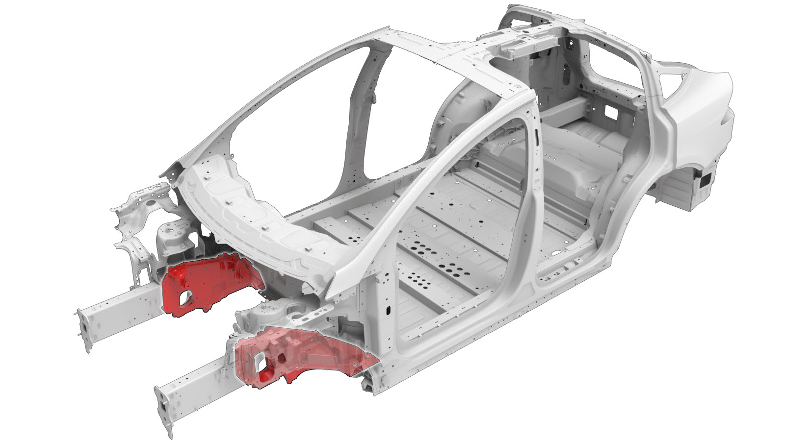 Correction code:
10101008202
10101008002
NOTE:
Unless explicitly stated in the procedure, the above
correction code includes all Collision Repair and Service
repair work required to perform this procedure, including
the linked Collision Repair procedures and linked Service
procedures. Do not stack Collision Repair correction
codes unless explicitly told to do so. Depending
on the damage to the vehicle, additional repairs may be
required.
Correction code:
10101008202
10101008002
NOTE:
Unless explicitly stated in the procedure, the above
correction code includes all Collision Repair and Service
repair work required to perform this procedure, including
the linked Collision Repair procedures and linked Service
procedures. Do not stack Collision Repair correction
codes unless explicitly told to do so. Depending
on the damage to the vehicle, additional repairs may be
required.
Repair Information
- Depending on the damage to this component, it may be possible to repair this component. Refer to Cast Torque Box Inner (Front) Repair Guidelines for more information.
- Review all collision repair general practices and safety documentation and wear the appropriate PPE (Personal Protective Equipment) before beginning this procedure.
- Properly mount the vehicle on a frame bench when performing this procedure.
Parts List
| Quantity | Description | Image / Notes |
|---|---|---|
| 1 | TORQUE BOX INNER MOTOR MOUNT (Torque Box Inner) | |
|
LH:
12 RH: 14 |
Bolt, Torx-head , T2000,M8x1.25-28,PF,[88],G1009 | Tesla part number 1621839-00-B. |
| 6 | Bolt, Torx-head , BLT,BFLG,TRX,M8X27.0[10.9]-M-NP-08 | Tesla part number 1022448-00-A. |
| 1 | Bolt BOLT,HH,M8-1.25x27,[109],G0110,M | Tesla part number 1621820-00-A. |
When ordering parts, refer to the Parts Catalog and enter the VIN of the vehicle being repaired to find the correct parts (and the part numbers) for the vehicle. Alternatively, use the search function in the Parts Catalog to find a specific part for the vehicle.
Repair Procedure
- Remove the Superbeam (Remove and Replace).
- RH component only: Remove the Air Suspension - Bundle - Front (Remove and Replace).
- Remove the Supermanifold (Remove and Replace).
- Remove the Drive Unit - Front (Remove and Install).
- Remove the Active Damper - Front - LH (Remove and Replace).
- LH component only: Remove the Pipe - Brake Junction to Jounce - LH (Remove and Replace).
-
Cut the original Sill
component at the indicated location and remove the bolt.
Cut Line
Reference Line/Point
- A = 24 mm.
- B = 213 mm.
or Bolts
NoteThe removed portion of the Sill will be reinstalled. -
Remove the original component.
-
Remove 2 mm. of material
from the surface shown to ensure the Shock Tower no longer contacts the new
Torque Box.
NoteIf your vehicle originally had a fastener at this location, it will not be replaced.
-
Prepare for installation.
NoteReinstall the portion of the Sill (shown in red) that was removed from the Sill.NoteA red X indicates a location where a factory-installed fastener is not being replaced. Secure this location using structural adhesive only.
or Bolts
-
Apply structural adhesive to the mating surfaces on the vehicle and the new component or components.
NoteApply structural adhesive to the mating surface of the Torque Box Inner and the portion of the Sill being reinstalled, and then fill any gaps with structural adhesive.NoteDo not apply structural adhesive to the area circled in red.
-
Install the new component or components.
Torque all bolts as to 30 Nm.
- Perform any necessary post-repair operations.
- LH component only: Install the Pipe - Brake Junction to Jounce - LH (Remove and Replace).
- Install the Active Damper - Front - LH (Remove and Replace).
- Install the Drive Unit - Front (Remove and Install).
- Install the Supermanifold (Remove and Replace).
- RH component only: Install the Air Suspension - Bundle - Front (Remove and Replace).
- Install the Superbeam (Remove and Replace).