Anchoring and Concrete Pad Details for Ground-mounting Powerwall 3 on Poured Concrete with Steel Posts
A11
In this mounting configuration, a concrete pad is constructed with vertical steel posts attached directly to the concrete pad. Powerwall 3 is mounted to the posts, allowing it to be vertically and laterally supported by the concrete pad.
Concrete Pad Sizes
The primary design constraint for mounting on a poured concrete pad with steel posts is the risk of wind blowing the Powerwall and pad over. As indicated in the table below, the required thickness and width of the concrete pad depend on which type of units are installed on it and how many units are installed.
| Pad Size | Pad Thickness | 1 Powerwall 3 |
|---|---|---|
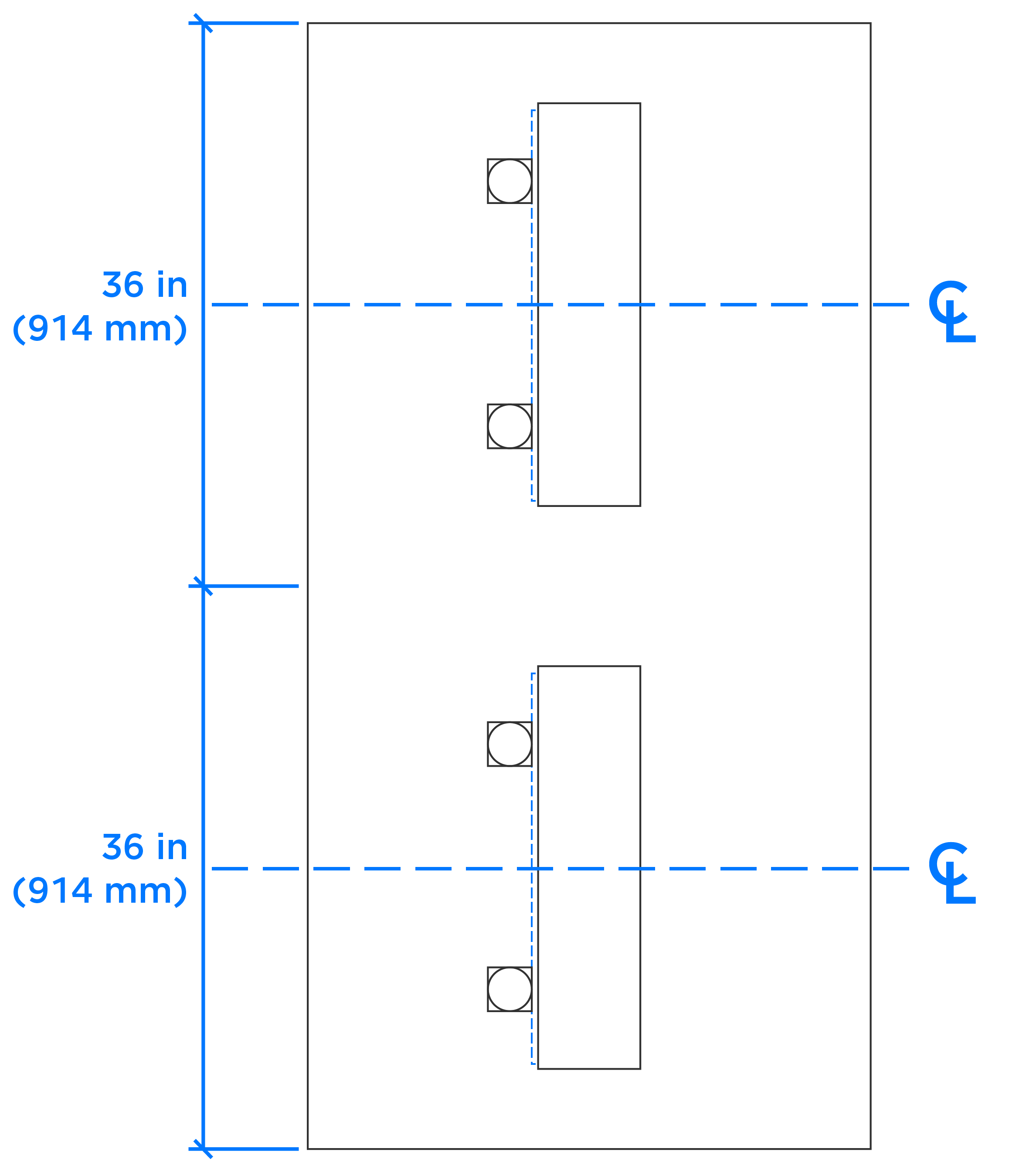
| 36 x 36 in (914 x 914 mm) | 6 in (152 mm) | Max wind 155 mph |
| 36 x 36 in (914 x 914 mm) | 9 in (229 mm) | Max wind 180 mph |
See Appendix A: Powerwall 3 Anchoring Details for installation scenarios which require site-specific calculations.
A12 - Anchoring and Concrete Pad Details for Ground-mounting Powerwall 3 on Poured Concrete with Steel Posts
Requirements for Poured Concrete Pad with Steel Posts
- Within the perimeter of the pad, excavate and remove all loose and organic material, compacting soil to a level surface. Embed the concrete in the soil per detail (below). Compact and fill a 4-inch thick base of crushed, course stone when 10PSF or more ground snow load is expected in site-specific design criteria
- Concrete used for pads shall have a minimum compressive strength of 3,000 PSI at 28 days. Work can begin 14 days after the pad is poured
- Concrete reinforcing shall
meet the temperature and shrinkage requirements of ACI 318
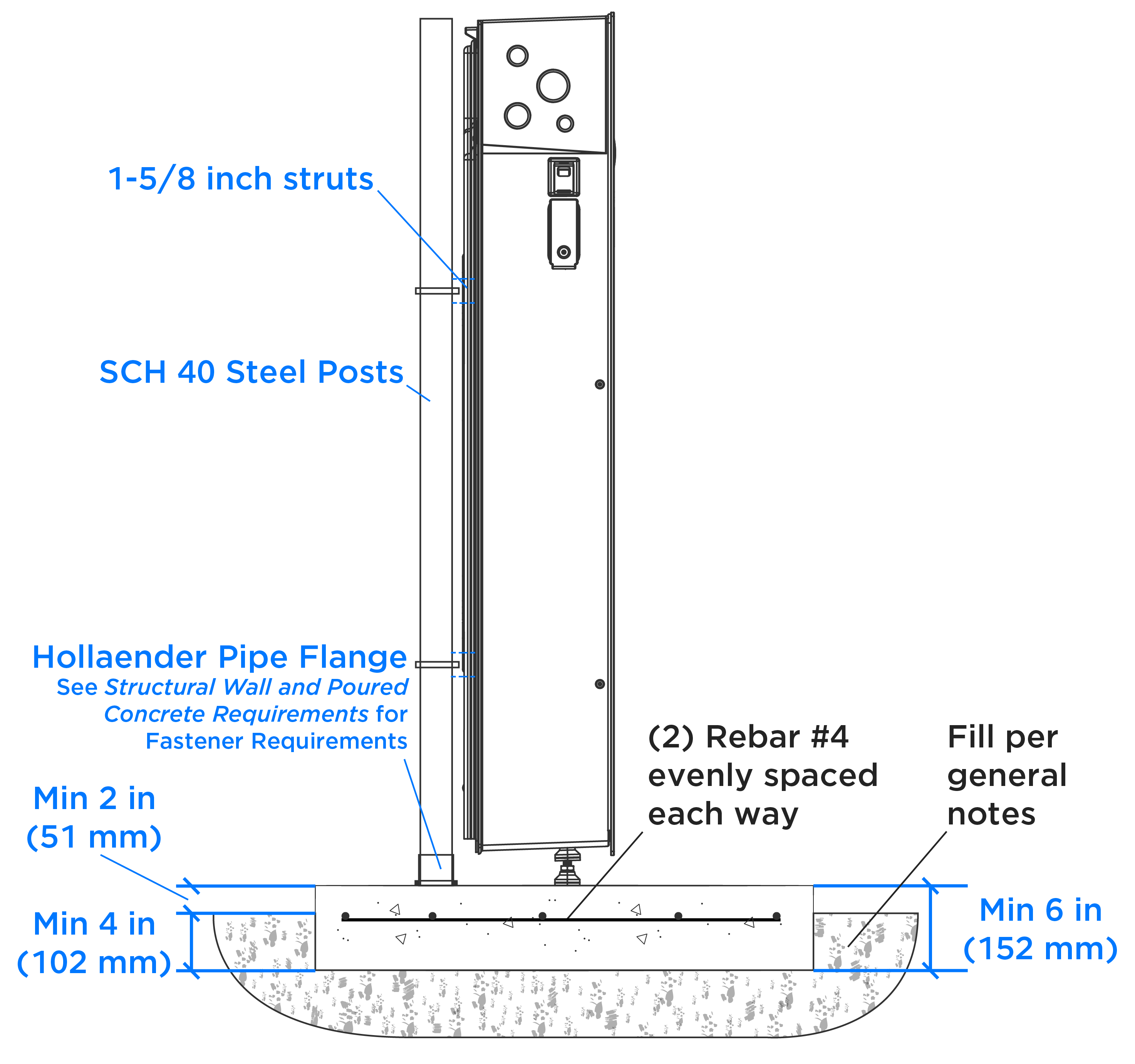
- #4 Rebars <=16 inch O.C. (both ways)
- ASTM A615 Grade 60 (FY = 60,000 PSI)
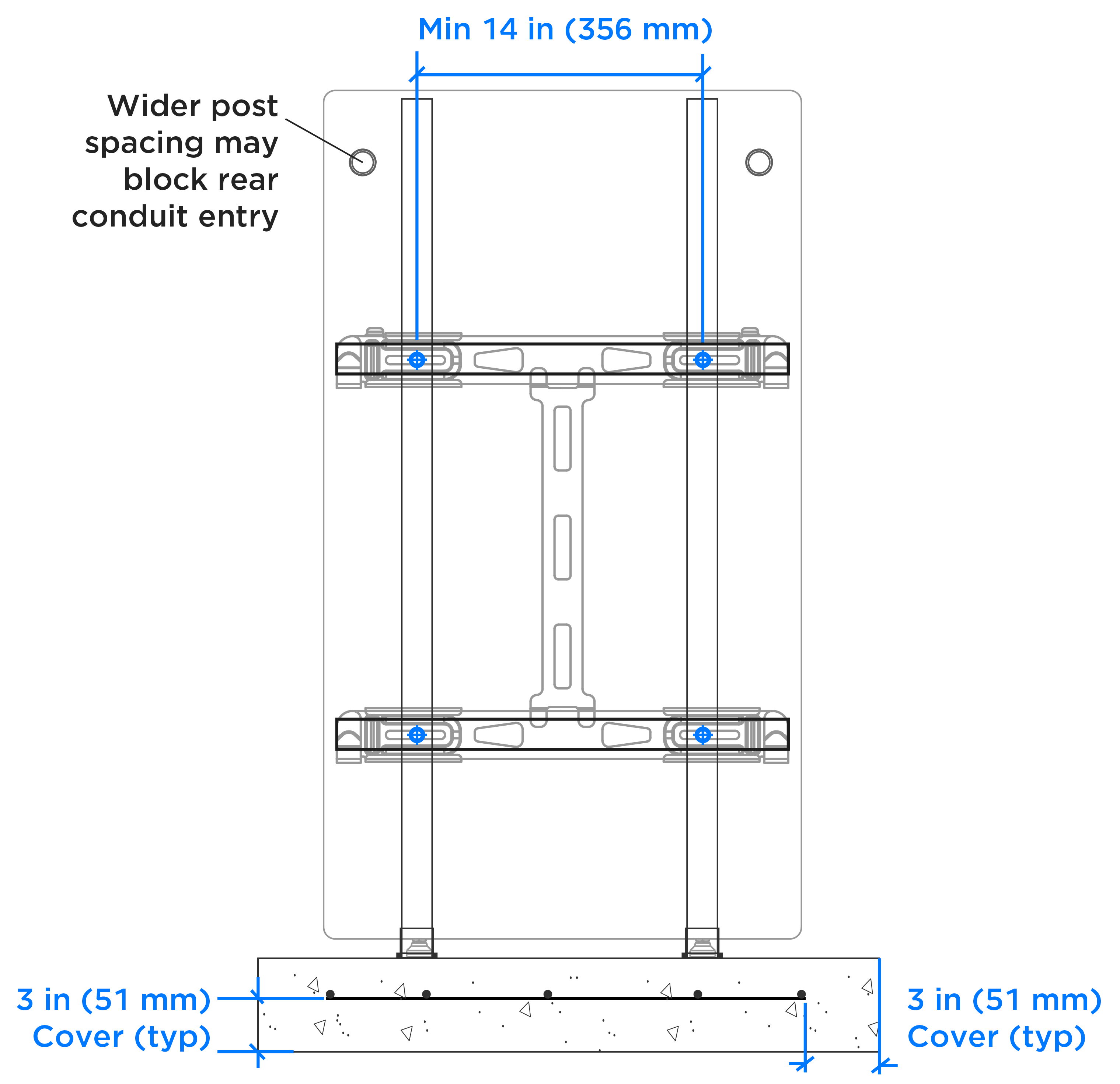
- Minimum 3 inch cover for concrete facing soil
- Posts shall be 2 inch SCH 40 steel pipes
- Each post is to be attached to the pad through a Hollaender pipe flange with (4) 3/8 inch Simpson Strong-Tie Titen HD concrete screws (ESR 2713) with minimum 2-½ inch embedment. An equivalent concrete anchor approved by the installing company's structural engineering team can be used with compliance letter
- All items to be cast in concrete, such as reinforcing steel, shall be securely and accurately positioned into the forms prior to placing the concrete
- Concrete anchors shall be installed with minimum 6 inch edge distance from all edges of the pad. Typical spacing between posts supporting the same Powerwall is 14 inches on center
- 1-5/8 inch struts and hardware shall be used to attach electrical equipment to posts
A13 - Anchoring and Concrete Pad Details for Ground-mounting Powerwall 3 on Poured Concrete with Steel Posts
A14 - Anchoring and Concrete Pad Details for Ground-mounting Powerwall 3 on Poured Concrete with Steel Posts