STEP 6: Connect Powerwall 3 to an Overcurrent Protection Device
Warning
Before terminating any conductors inside Powerwall 3, ensure that the Enable switch is turned OFF to de-energize the system. Confirm lack
of voltage at the AC and PV terminals before proceeding.
- Disconnect the AC circuit breaker of the main service disconnect and secure it against reconnection.
- Connect the Powerwall 3 AC power conductors to the main
panel or sub panel according to the electrical service type.NoteEach Powerwall 3 requires a 60 A circuit overcurrent protection device. This device serves as the disconnect for Powerwall 3 and must be wired in accordance with local wiring codes and regulations.NoteTesla recommends a 60 A circuit breaker for overcurrent protection, as a circuit breaker can easily be reset by the homeowner if needed. As such, the required overcurrent protection device is referred to as the Powerwall 3 circuit breaker throughout this manual. Alternative overcurrent protection devices, such as a fused disconnect, may be used and may result in a poor customer experience if the homeowner cannot reset the system in the unlikely event of a trip.
- (Conduit installations only) Run conduit as needed and attach the conduit fitting to the Powerwall 3 AC wiring knockout.
- Run the AC power conductors and the
equipment grounding conductor from the main panel through the conduit or cable
gland, pulling 24 inches (610 mm) of wiring into the enclosure. Route the conductors
to the appropriate terminals, creating a service loop with the extra wiring (see
Powerwall 3 AC
Wiring for an example of a service loop).CAUTIONAny wire routing must be done through the wire management tabs at the top of the enclosure. Do not route loose wires through the front of the enclosure or over the Tesla Asset Controller.
- Clear out any debris that may be
present in the AC wiring terminals.DANGERMetal debris like loose wires or metal shavings could create a high voltage risk when Powerwall is turned on.
- Connect the Powerwall 3 equipment grounding
conductor:
- Strip the conductor insulation up to 3/4-inch (19 mm).
- Insert the grounding conductor in an equipment grounding terminal and tighten the screw in the Earth terminal to 35 in-lb (4 Nm).
- For each AC conductor:
- Strip the conductor insulation up to 7/16-inch (11 mm). Add a ferrule if the conductor is finely stranded.
- Insert a cabinet or electronics tip slotted screwdriver (up to 3/16-inch or 4.5 mm) into the screwdriver slot to open the terminal.
- Insert the conductor as far
as possible into the terminal and remove the screwdriver from the
screwdriver slot to close the terminal.
Figure 1. Spring Terminal with Screwdriver and Insert Conductor in Terminal 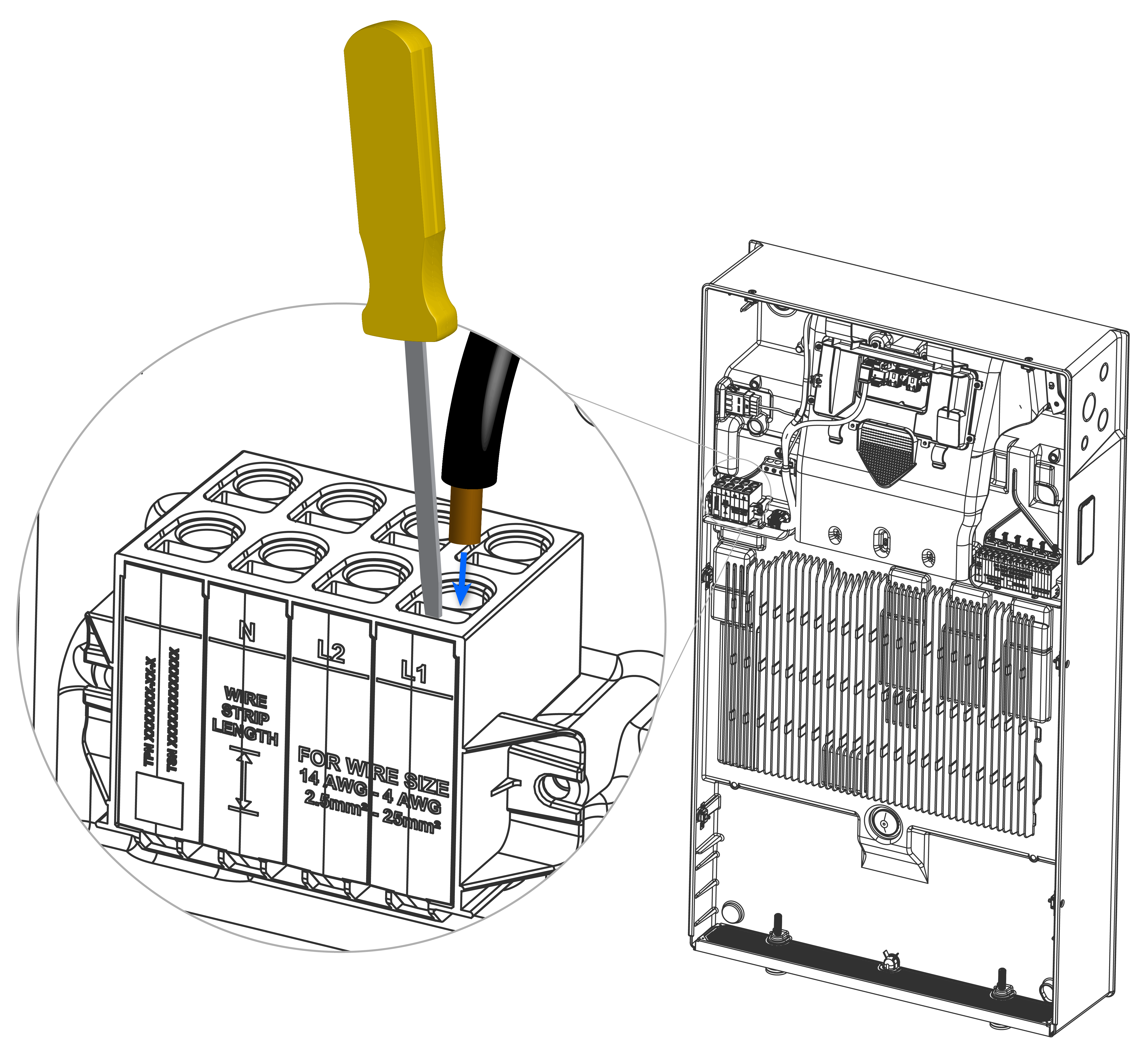 WarningEnsure the conductors are inserted into the round terminals and not the rectangular screwdriver slots. Inserting the conductors in the screwdriver slots can result in fire.
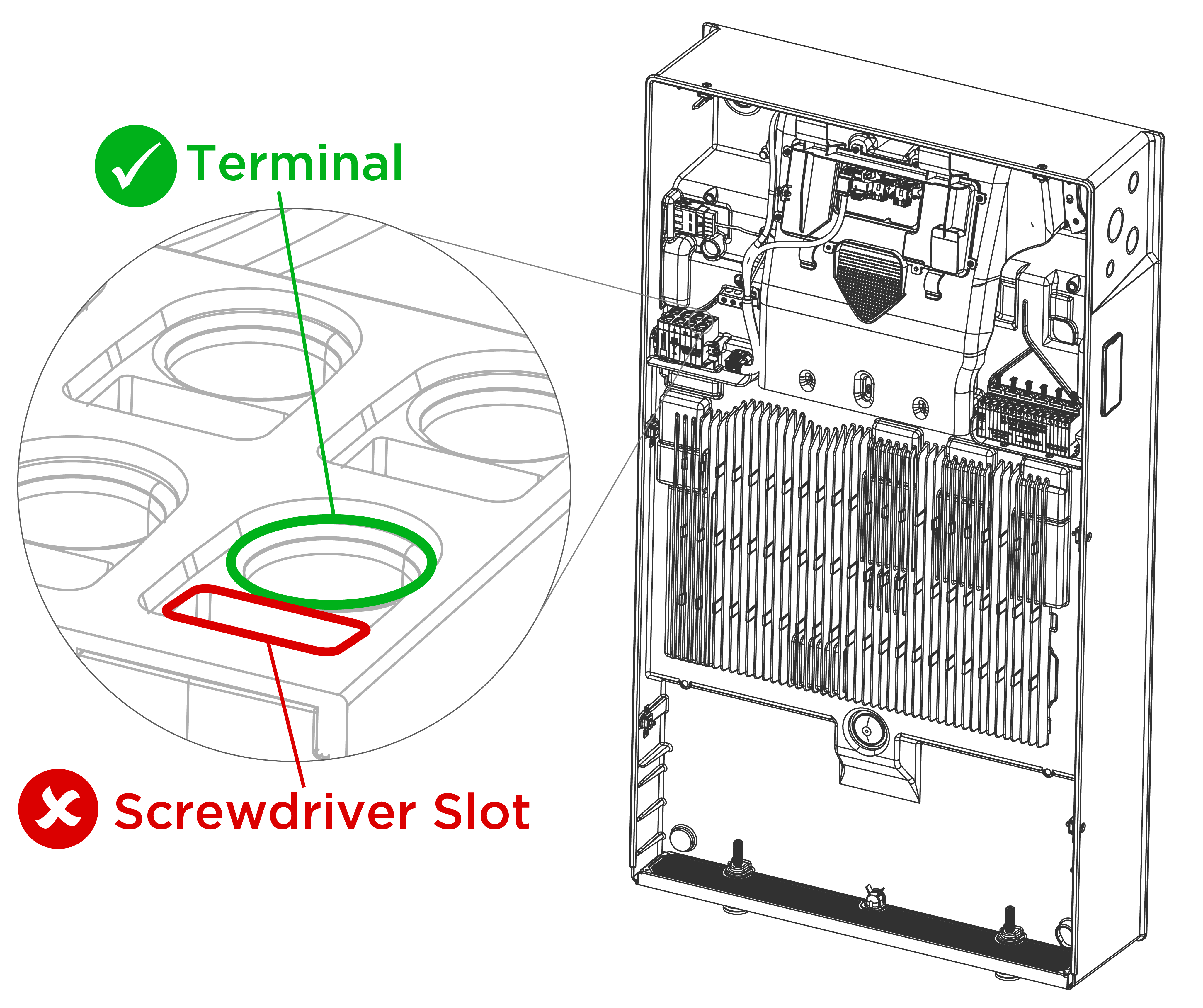
- Perform a pull test to ensure
the conductor is fully seated in the terminal. Push the conductor back in
after the pull test.
Figure 2. Powerwall 3 AC Wiring 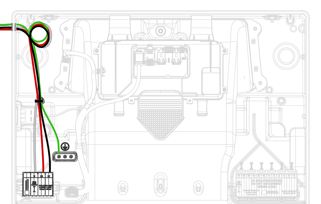
- After installing the AC conductors and equipment grounding conductor, gather them and secure them with the provided cable tie as shown above.
Required UL 1741 PCS Compliance Information
Note
The Tesla Powerwall 3 system is certified to UL 1741
PCS for the energy storage system (ESS) operating modes of import and export only.
The installer can select three modes of operation for the system: No Site Export, PV
Only Export, and PV, Battery Export.
- NO SITE EXPORT: The battery and solar will not export beyond the site meter, other than inadvertent export.
- PV ONLY EXPORT: The battery will not export beyond the site meter, other than inadvertent export. The export at the site meter will be limited to the export from as measured by the solar meter.
- PV, BATTERY EXPORT: The battery and solar will export beyond the site meter.
Note
To achieve UL 1741 PCS Import Only
behavior, either PV ONLY
EXPORT or NO SITE
EXPORT must be selected. When the selected Grid Code applies to a region
that requires UL 1741 PCS, such as California UL 1741 SA, the default setting is PV ONLY EXPORT. In the
locally hosted Configuration Interface it is possible to further restrict the system
to NO SITE EXPORT; however
once set, it is not possible to change back to PV ONLY EXPORT. It is not
possible to configure the system to allow BATTERY EXPORT in this
mode.
Note
To achieve UL 1741 PCS Export Only
behavior, PV, BATTERY EXPORT
must be selected and the import rule must be set to charge only from solar (and not
charge from the grid). When the selected Grid Code applies to a region that requires
UL 1741 PCS, such as California UL 1741 SA, the default setting is PV ONLY EXPORT. In the
locally hosted Configuration Interface it is possible to further restrict the system
to NO SITE EXPORT; however
once set, it is not possible to change back to PV ONLY EXPORT or PV, BATTERY EXPORT.
Note
This system is equipped with a
power control system (PCS) which is suitably rated to provide branch circuit
overcurrent protection. The controlled current setting shall not exceed the rating
of any controlled busbars or conductor ampacity.
Note
The PCS controlled current setting
for each PCS controlled conductor or bus bar shall be indicated with a field applied
marking label on the conductor or in close proximity to the busbar.
Warning
Only qualified
personnel shall be permitted to set or change the setting of the maximum operating
current of the PCS. The maximum PCS operating current setting shall not exceed the
busbar rating or conductor ampacity of any PCS controlled busbar or
conductor.
Warning
Configuration of
power control settings system or changes to settings shall be made by qualified
personnel only. Incorrect configuration or setting of the power control settings may
result in unsafe conditions.
Note
The maximum operating currents in
controlled busbars or conductors are limited by the settings of the power control
system (PCS) and may be lower than the sum of the currents of the connected
controlled power sources. The settings of the PCS controlled currents may be used
for calculation of the design currents used in the relevant sections of NEC Article
690 and 705.
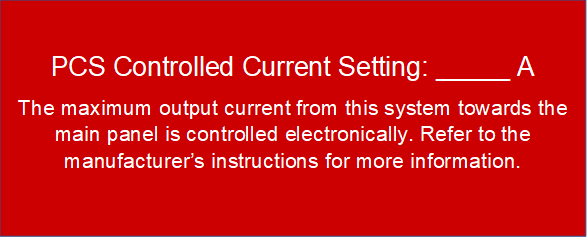
Note
Maximum PCS Controlled Current
setting: 200 A.