Make PV Power Connections
- Turn Powerwall 3 OFF to de-energize the system.WarningWiring Powerwall 3 while it is energized may result in injury and/or product damage. Confirm lack of voltage at the PV terminals before proceeding.
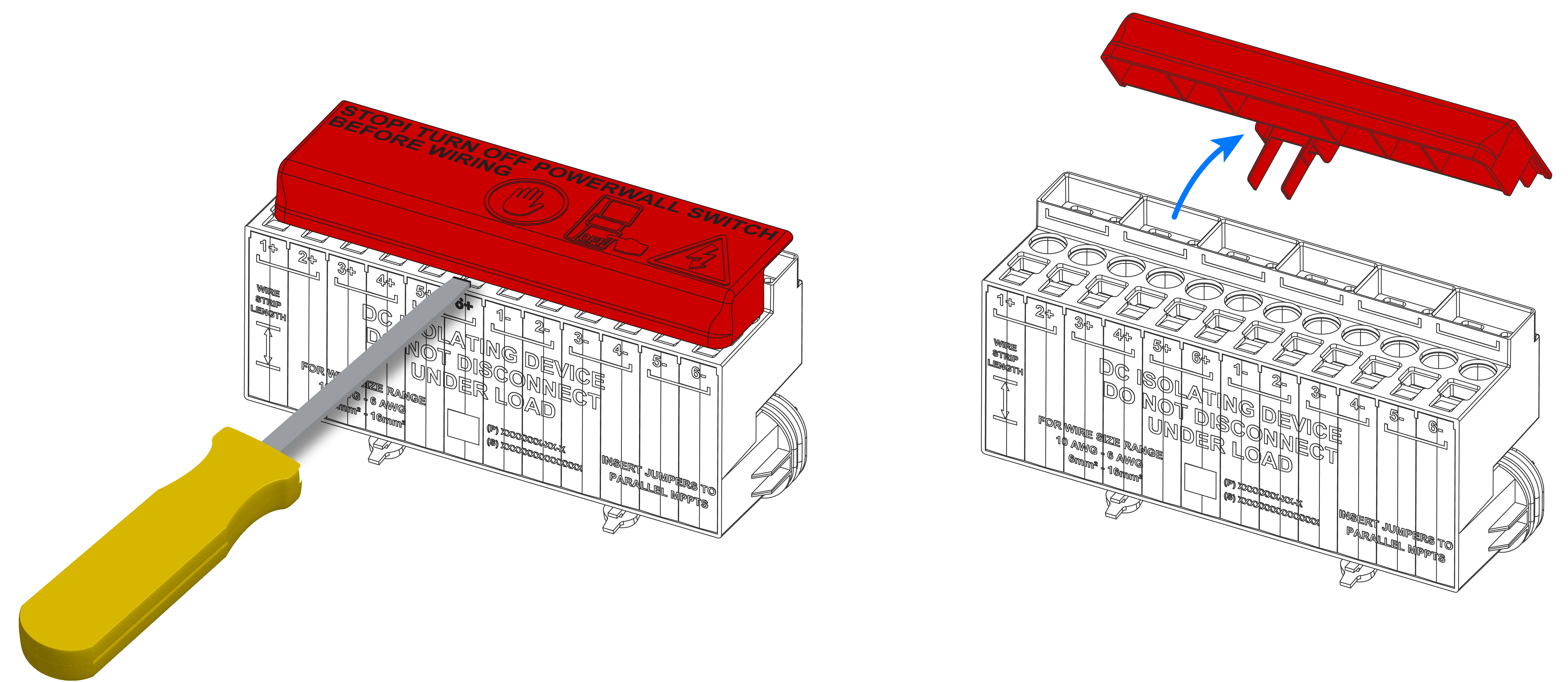
- A warning cover is installed over the PV
connector to remind installers to turn Powerwall 3 OFF before connecting any PV conductors. To remove the warning cover:
- Position a flat head screwdriver above
MPPT 6+ and pry the warning cover off of the PV connector, exposing the terminals.
 CAUTIONBe careful not to damage the PV connector.
 - Recycle the warning cover.
- Position a flat head screwdriver above
MPPT 6+ and pry the warning cover off of the PV connector, exposing the terminals.
- Route the PV conductors and PV array equipment grounding conductor into the enclosure.
- Connect the PV array equipment grounding
conductor to an equipment grounding terminal in Powerwall:
- Strip the conductor insulation up to 3/4-inch (19 mm).
- Insert the grounding conductor in an equipment grounding terminal and tighten the screw in the Earth terminal to 35 in-lb (4 Nm).
CAUTIONAny wire routing must be done through the wire management tabs at the top of the enclosure. Do not route loose wires through the front of the enclosure or over the Tesla Asset Controller. - For each PV input:
- Strip the conductor insulation up to 3/8-inch (9.5 mm). Add a ferrule if the conductor is finely stranded.
- Insert a cabinet or electronics tip slotted screwdriver (up to 3/16-inch or 4.5 mm) into the actuation shaft to open the terminal.
- Insert the conductor as far as possible
into the terminal and remove the screwdriver from the actuation shaft to close the
terminal.
Figure 1. Spring Terminal with Screwdriver and Insert Conductor in Terminal 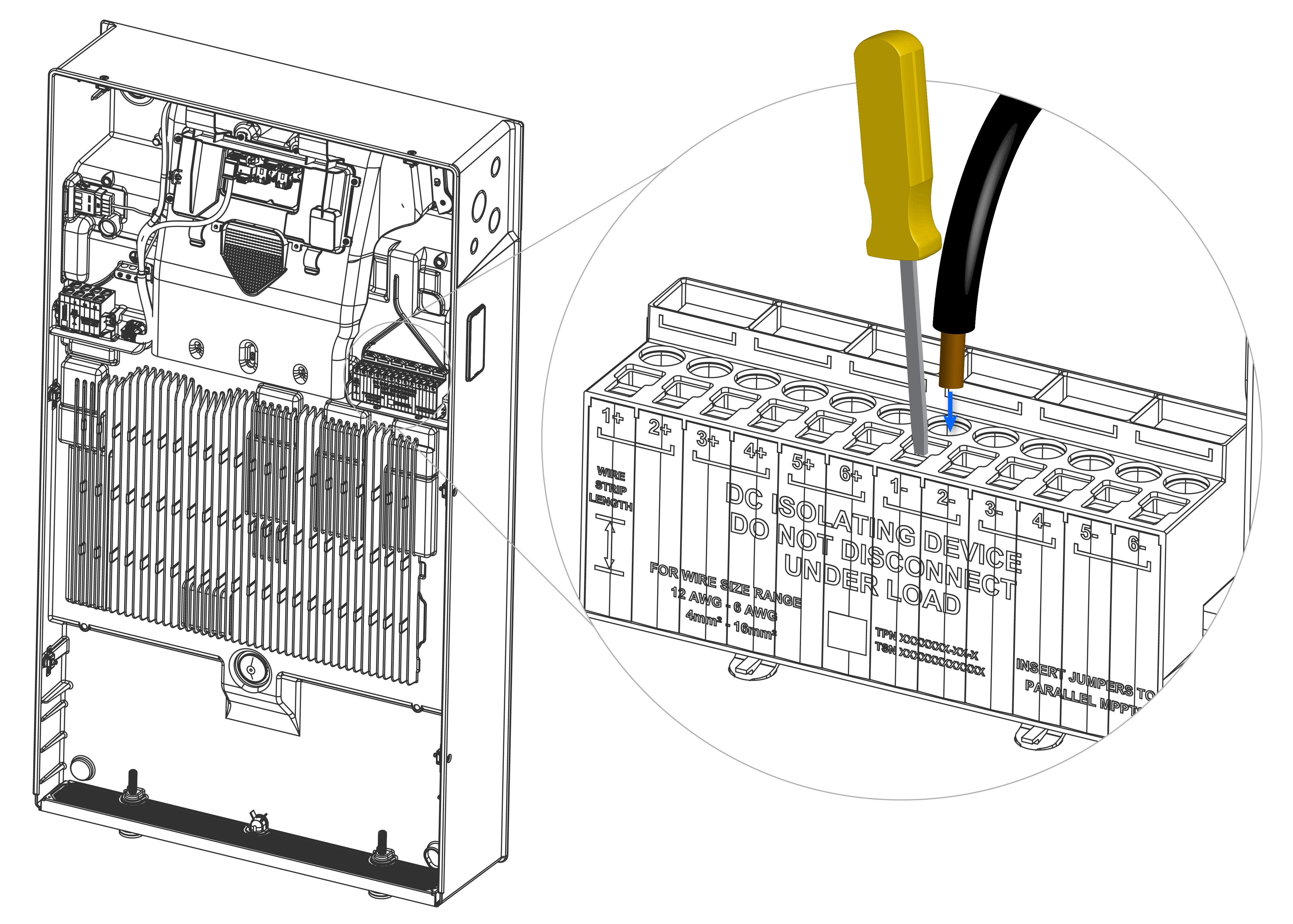 WarningEnsure the conductors are inserted into the round terminals and not the rectangular screwdriver slots. Inserting the conductors in the screwdriver slots can result in fire.
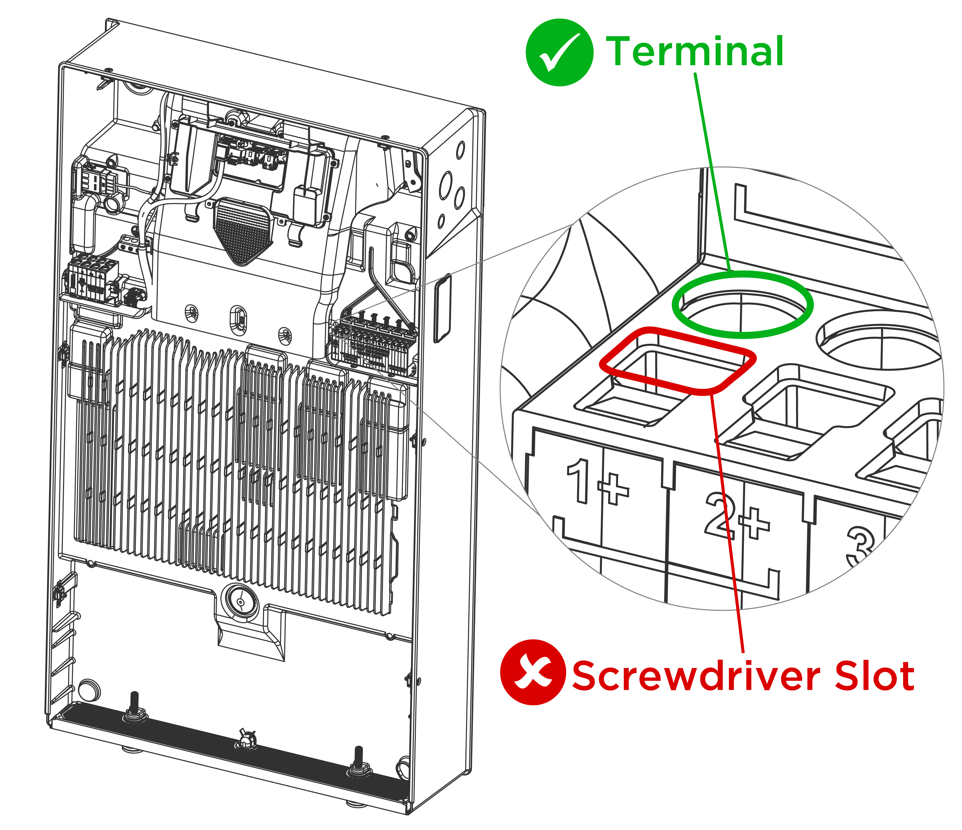
- Perform a pull test on each conductor
(pulling straight up) to confirm it is fully seated in the terminal. Push the conductor
back in after the pull test.
Figure 2. Powerwall 3 PV Wiring and Equipment Grounding Conductor 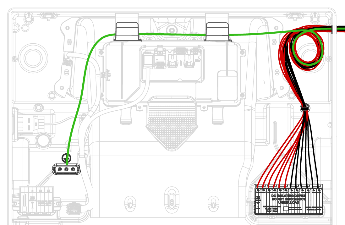
- After installing all PV conductors, gather them and secure them with the provided cable tie as shown above.
Note
The building and the system shall be marked
in accordance with Section 690.56(C) of the NEC (NFPA 70) “Only conductors leaving the
footprint of the array are controlled” on PV wiring.